EP1502677A1 - Mold for continuous casting - Google Patents
Mold for continuous casting Download PDFInfo
- Publication number
- EP1502677A1 EP1502677A1 EP04016971A EP04016971A EP1502677A1 EP 1502677 A1 EP1502677 A1 EP 1502677A1 EP 04016971 A EP04016971 A EP 04016971A EP 04016971 A EP04016971 A EP 04016971A EP 1502677 A1 EP1502677 A1 EP 1502677A1
- Authority
- EP
- European Patent Office
- Prior art keywords
- electromagnetic stirring
- stirring apparatus
- back plate
- apparatus housing
- molten steel
- Prior art date
- Legal status (The legal status is an assumption and is not a legal conclusion. Google has not performed a legal analysis and makes no representation as to the accuracy of the status listed.)
- Granted
Links
Images



Classifications
-
- B—PERFORMING OPERATIONS; TRANSPORTING
- B22—CASTING; POWDER METALLURGY
- B22D—CASTING OF METALS; CASTING OF OTHER SUBSTANCES BY THE SAME PROCESSES OR DEVICES
- B22D11/00—Continuous casting of metals, i.e. casting in indefinite lengths
- B22D11/04—Continuous casting of metals, i.e. casting in indefinite lengths into open-ended moulds
- B22D11/049—Continuous casting of metals, i.e. casting in indefinite lengths into open-ended moulds for direct chill casting, e.g. electromagnetic casting
-
- B—PERFORMING OPERATIONS; TRANSPORTING
- B22—CASTING; POWDER METALLURGY
- B22D—CASTING OF METALS; CASTING OF OTHER SUBSTANCES BY THE SAME PROCESSES OR DEVICES
- B22D11/00—Continuous casting of metals, i.e. casting in indefinite lengths
- B22D11/10—Supplying or treating molten metal
- B22D11/11—Treating the molten metal
- B22D11/114—Treating the molten metal by using agitating or vibrating means
- B22D11/115—Treating the molten metal by using agitating or vibrating means by using magnetic fields
-
- B—PERFORMING OPERATIONS; TRANSPORTING
- B22—CASTING; POWDER METALLURGY
- B22D—CASTING OF METALS; CASTING OF OTHER SUBSTANCES BY THE SAME PROCESSES OR DEVICES
- B22D41/00—Casting melt-holding vessels, e.g. ladles, tundishes, cups or the like
- B22D41/50—Pouring-nozzles
- B22D41/62—Pouring-nozzles with stirring or vibrating means
-
- F—MECHANICAL ENGINEERING; LIGHTING; HEATING; WEAPONS; BLASTING
- F16—ENGINEERING ELEMENTS AND UNITS; GENERAL MEASURES FOR PRODUCING AND MAINTAINING EFFECTIVE FUNCTIONING OF MACHINES OR INSTALLATIONS; THERMAL INSULATION IN GENERAL
- F16B—DEVICES FOR FASTENING OR SECURING CONSTRUCTIONAL ELEMENTS OR MACHINE PARTS TOGETHER, e.g. NAILS, BOLTS, CIRCLIPS, CLAMPS, CLIPS OR WEDGES; JOINTS OR JOINTING
- F16B35/00—Screw-bolts; Stay-bolts; Screw-threaded studs; Screws; Set screws
Definitions
- the present invention relates to the shape and structure of a mold for continuous casting.
- the present invention relates to the shape and structure of a mold for continuous casting having an electromagnetic stirring apparatus, which is equipped for stirring molten steel in the continuous casting mold.
- Electromagnetically stirring molten steel in a continuous casting mold has been used in the background art to eliminate non-metallic inclusions or gas contained in the poured molten steel.
- a molten steel continuous casting mold equipped with an electromagnetic stirring apparatus has been used for this purpose.
- a molten steel continuous casting mold equipped with an electromagnetic stirring apparatus includes a copper plate for forming a casting space.
- An electromagnetic stirring apparatus housing is installed in contact with the copper plate for accommodating the electromagnetic stirring apparatus.
- a water feeding header and a drainage header are also included in the molten steel continuous casting mold.
- a back plate e.g., made of stainless steel, is mounted between the copper plate and the electromagnetic stirring apparatus housing to reinforce a rigidity of the molten steel continuous casting mold.
- the water feeding header and the drainage header are disposed below the electromagnetic stirring apparatus housing so that the electromagnetic stirring apparatus housing can be set on the upper portion of the mold, which is one of the features of the disclosed technology. Setting an electromagnetic stirring apparatus on the upper portion of the mold makes it possible to improve the stirring of the molten steel. This leads to a steel product such as a cast slab having an excellent surface quality.
- the copper plate for forming the casting space always contacts the high temperature molten steel in the mold. This can cause cracking and erosion of the copper plate. Therefore, it becomes necessary to dismantle the copper plate for repair or replacement.
- many molten steel continuous casting molds with an electromagnetic stirring apparatus according to the background art include the copper plate and the electromagnetic stirring apparatus housing being fixed with a bolt located inside the electromagnetic stirring apparatus housing. For this reason, when the copper plate is dismantled for replacement or repair, it is also necessary to dismantle the electromagnetic stirring apparatus accommodated in the housing. In other words, a majority of the parts constituting the mold must be disassembled, which consumes a lot of time.
- One solution to reduce the time would be to keep a spare unit having an integrated electromagnetic stirring apparatus housing and copper plate. It would then be possible to replace both the housing and the copper plate at the same time with the spare unit when repair or replacement of the old copper plate is needed. However the provision of a spare unit can be very expensive.
- An object of the present invention is to provide a structure that makes it easier to dismantle the copper plate in a molten steel continuous casting mold.
- the casting mold includes a copper plate for forming a casting space (a horizontal section of the copper plate is usually approximately rectangular; however, other shapes are possible as well), a back plate and an electromagnetic stirring apparatus housing.
- the back plate is disposed outside of the copper plate and in contact with the copper plate to reinforce the rigidity of the casting mold.
- the electromagnetic stirring apparatus housing accommodates an electromagnetic stirring apparatus inside.
- Another object of the present invention is to provide a structure to prevent a reduction of the electromagnetic stirring thrust due to the inclusion of a back plate.
- One aspect of the present invention is directed to a molten steel continuous casting mold, comprising: a copper plate, said copper plate for forming a casting space; a back plate disposed outside of and contacting said copper plate; and an electromagnetic stirring apparatus housing disposed outside of the back plate, said electromagnetic stirring apparatus housing accommodating an electromagnetic stirring apparatus therein, wherein a wall of the electromagnetic stirring apparatus housing which contacts the back plate has an extended portion, and the back plate and the electromagnetic stirring apparatus housing are fixed together by a bolt located at only the extended portion of said wall of the electromagnetic stirring apparatus housing.
- a second aspect of the present invention is directed to a molten steel continuous casting mold, comprising: a copper plate, said copper plate for forming a casting space; a back plate disposed outside of and contacting said copper plate; and an electromagnetic stirring apparatus housing disposed outside of the back plate, said electromagnetic stirring apparatus housing accommodating an electromagnetic stirring apparatus therein, wherein a wall of the electromagnetic stirring apparatus housing which contacts the back plate has an opening formed therethrough, said opening receiving an end of an iron core of the electromagnetic stirring apparatus therein.
- Figure 1 is a vertical sectional view of one half of the mold including a long copper plate according to one of embodiment of the present invention
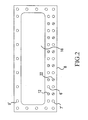
- Figure 2 is a vertical sectional view of the mold of Figure 1 along the line 2-2 of Figure 1;
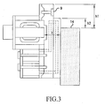
- Figure 3 is a vertical sectional view of one half of the mold of another embodiment of the present invention.
- Figure 4-1 is a graph showing a relation between a distance from an end of an iron core to an inner surface of a casting space and a rigidity of a casting mold
- Figure 4-2 is a graph showing a relation between a distance from an end of an iron core to an inner surface of a casting space and an index number representing a thrust of electromagnetic stirring;
- Figure 5 is an explanatory view of how to dismantle a copper plate of a mold for continuous casting.
- a molten steel continuous casting mold (hereinafter referred to simply as a "mold”) includes a pair of opposing long copper plates and a pair of opposing short copper plates which are disposed in directions orthogonal to each other to form an approximately rectangular casting space. Molten steel is poured in the casting space from above.
- the continuous casting mold of the present invention operates in generally the same manner as a continuous casting mold according to the background art. In view of this, only the differences between the present invention and the background art will be discussed below.
- Figure 1 shows a vertical section of one half of the mold including a long copper plate according to one embodiment of the present invention.
- a vertical section of the mold through the other long copper plate would have similar structure to the vertical section of Figure 1. Accordingly, only one of the long copper plates will be specifically discussed.
- a back plate 10 is fixed to one wall 8 of the electromagnetic stirring apparatus housing 1 by bolts 6, 7, and 9.
- the wall 8 of the electromagnetic stirring apparatus housing 1 and a back plate 10 have cooperating concave/convex structure portions 17.
- a concave portion of the wall 8 can fit in a convex portion of the back plate 10 and a convex portion of the wall 8 can fit in a concave portion of the back plate 10.
- the wall 8 and the back plate 10 are fixed together by bolts 6, 7 and 9.
- the concave/convex structure portions 17 of the wall 8 and the back plate 10 make it easy to position the wall 8 and back plate 10 together for assembly; however, such structure is described only as preferable.
- Fixing the back plate 10 to the wall 8 of the electromagnetic stirring apparatus housing 1 increases the rigidity of the mold.
- the back plate 10 is also fixed to the copper plate 11, which forms the casting space in which the molten steel 14 is poured.
- the back plate 10 is made of, for example, stainless steel.
- the back plate 10 and the copper plate 11 can be fixed using any well-known manner such as welding, pinning, bolting or the like.
- the wall 8 of the electromagnetic stirring apparatus housing 1 and the other walls of the electromagnetic stirring apparatus housing 1 can be fixed together by welding.
- An electromagnetic stirring apparatus including an iron core 3 is accommodated in the electromagnetic stirring apparatus housing 1. It is significant to note that the bolts 6, 7, and 9 fixing the wall 8 of the housing 1 and the back plate 10 are not located inside the housing 1.
- the wall 8 of the electromagnetic stirring apparatus housing 1 has an extended portion and the wall 8 and the back plate 10 are fixed to each other by only a bolt located at the area of the extended portion (outside of the electromagnetic stirring apparatus housing).
- the wall 8 extends in upward, downward, left and right directions from the outside of the housing 1.
- a top end of the top extended portion and a top end of the back plate 10 are positioned at the same level.
- a condition h 1 > h 2 is satisfied, where h 1 is a distance between a top end of the top extended portion (or the back plate 10) and a surface level 14 of the molten steel in the casting space, and h 2 is a distance between a top end of the copper plate 11 and a surface level 14 of the molten steel in the casting space.
- the top ends of the top extended portion and the back plate 10 are positioned above the top end of the copper plate 11.
- the bolt 9 that fixes the wall 8 and the back plate 10 is located at the area of the top extended portion positioned above the top end of the copper plate 11.
- the bolts 6 and 7 that fix the wall 8 and the back plate 10 are located at the area of the bottom extended portion. It should be noted that additional bolts 6, 7 and 9, respectively, are received in the remaining bolt holes in the top, bottom, right and left extended portions of the wall 8 in order to further connect the wall 8 to the back plate 10 (see Figure 2).
- the mold structure of the present invention has been made in consideration of the above circumstances. Specifically, the present invention has been made to easily carry out operations from the floor located above the mold, increase a rigidity of the mold, increase a fixing strength of the back plate and the electromagnetic stirring apparatus housing, and easily dismantle the copper plate.
- the bolts 6, 7, and 9 fixing the wall 8 of the electromagnetic stirring apparatus housing 1 and the back plate 10 are not located inside the housing 1. This can make it very easy to dismantle the copper plate for repair or replacement. The procedure for dismantling the copper plate will be described below.
- the mold is designed to reduce the distance between an end of the iron core 3 facing toward the casting space (hereinafter referred simply to as "end of the iron core") of the electromagnetic stirring apparatus and the molten steel in the casting space for increasing an electromagnetic stirring thrust.
- the wall 8 has an opening 16 formed therethrough for receiving the end of the iron core 3, so that the end of the iron core 3 can be moved closer to the casting space, i.e., closer to the molten steel. This leads to an increase of the electromagnetic stirring thrust. It should be noted that forming the opening may cause a reduction in the strength of the electromagnetic stirring apparatus housing 1; however, this can be compensated for by fixing the back plate 10 to the housing 1.
- the bolts used to fix the housing and the copper plate or the housing and the back plate are located inside the housing. Accordingly, it is impossible to form the opening 16 in the wall 8 as in the embodiment of the present invention.
- the wall 8 of the electromagnetic stirring apparatus housing 1 has an extended portion.
- the wall 8 and the back plate 10 are fixed to each other by bolts located only at the area of the extended portion (the top, bottom, right and left extended portions).
- This structure enables the wall 8 to be capable of having the opening 16.
- Figure 1 shows that the back plate 10 has a concave portion 15 in communication with the opening, so that a distance between an inner surface of the casting space and the end of the iron core 3 of the electromagnetic stirring apparatus can be reduced.
- the wall 8 of the electromagnetic stirring apparatus housing 1 has an extended portion, and the wall 8 and the back plate 10 are fixed to each other by bolts located only at the area of the extended portion.
- This structure according to the present invention also allows the back plate 10 to have the concave portion 15.
- a water passage 13 is formed by a groove on the surface of the copper plate 11 that faces the back plate 10. Cooling water from a water feeding header 5 disposed below the electromagnetic stirring apparatus housing 1 is fed to the water passage 13 through a water feeding hole 22 formed in the wall 8 and the back plate 10. The cooling water retums into a drainage header 4 through a drainage passage 12 formed in the wall 8 and the back plate 10 after passing through the water passage 13.
- the form of the water passage is not limited to the one shown in Figure 1.
- the water passage 13 can be formed by a long hole in the copper plate or a groove on the surface of the back plate 10 that faces the copper plate.
- the form of the water drainage passage 12 is not limited to the one shown in Figure 1.
- the drainage passage can be formed by a groove on the surface of the back plate 10 that faces the copper plate 11 or a groove on the surface of the copper plate 11 that faces the back plate 10.
- the electromagnetic stirring apparatus can be mounted on the upper portion of the mold. This leads to a good stirring of the molten steel and results in products, such as cast slabs, that have an excellent surface quality.
- Figure 2 is a vertical section of one half of the mold taken on line 2-2 in Figure 1.
- An opening 16 for receiving an end of the iron core 3 and holes 6', 7' and 9' for receiving the bolts 6, 7 and 9, respectively, are provided in the wall 8.
- the wall 8 includes a water feeding hole 22 and a drainage hole 12, which is a part of the drainage passage.
- Figure 2 indicates that the wall 8 and the back plate 10 are fixed by bolts 6, 7 and 9 at the extended portion of the wall 8 above the top end of the copper plate (above the outside of the electromagnetic stirring apparatus housing at the top extended portion) and at bottom, left and right extended portions.
- the bolts connecting the wall 8 and the back plate 10 are located at the top extended portion, the bottom extended portion, the left extended portion and the right extended portion, but are not located within the electromagnetic stirring apparatus housing 1. This provides a good fixing strength between the wall 8 and the back plate 10.
- FIG. 1 is a graph showing a relation between a distance from an end of the iron core 3 to an inner surface of a casting space (corresponding to distance "t” in Figure 1) and the rigidity of a casting mold.
- Figure 4-2 is a graph showing a relation between a distance from an end of the iron core to an inner surface of a casting space (corresponding to distance "t” in Figure 1) and an index number representing an electromagnetic stirring thrust.
- Figure 3 is a vertical section of one half of the mold of another embodiment of the present invention.
- the wall 8 of the electromagnetic stirring apparatus housing 1 has an extended portion and the wall 8 and the back plate 10 are fixed to each other by bolts located only at the area of the extended portion.
- This structure enables the bolt to be removed and to fix the wall 8 and the back plate 10 from the area outside of the electromagnetic stirring apparatus housing 1.
- the wall 8 extends upward from the housing 1.
- the top ends of the extended portion and the back plate 10 are positioned above the top end of the copper plate 11.
- the bolts 9 used to fix the wall 8 and the back plate 10 are located at the area of the extended portion positioned above the top end of the copper plate 11.
- This top extended portion above the top end of the copper plate 11 has to have a space for setting the bolts 9.
- the bolts 9 are screwed in from the casting space side toward the outside. This makes it possible to reduce the distance h 1 as much as possible when compared to the structure in Figure 1.
- a maintenance piece 20 having a width-adjusting bolt 21 is fixed on the top end portion of the back plate 10.
- the bolts 6, 7, and 9 are then unscrewed so that the wall 8 and the back plate 10 can be detached from each other.
- the width-adjusting bolt 21 By turning the width-adjusting bolt 21, the back plate 10 and the copper plate 11 are moved inward toward the casting space by a distance equal to the depth of the concave/convex structure 17.
- the back plate 10 and the copper plate 11 are then lifted up with a crane (not shown) to be removed from the mold.
- a reverse procedure is used to re-assemble the copper plate 11 and the back plate 10.
- the present invention makes it possible to dismantle the copper plate 11 very easily, which results in a great reduction of operation time for replacement of the copper plate 11.
- the present invention also makes it possible to avoid the necessity of a spare unit for the electromagnetic stirring apparatus housing 1, which results in a decrease in cost.
- the present invention makes it possible to reduce the distance between the electromagnetic stirring apparatus and the molten steel in the casting space, which can avoid a degradation of the electromagnetic stirring thrust.
Landscapes
- Engineering & Computer Science (AREA)
- Mechanical Engineering (AREA)
- General Engineering & Computer Science (AREA)
- Continuous Casting (AREA)
Abstract
Description
- The present invention relates to the shape and structure of a mold for continuous casting. In particular, the present invention relates to the shape and structure of a mold for continuous casting having an electromagnetic stirring apparatus, which is equipped for stirring molten steel in the continuous casting mold.
- Electromagnetically stirring molten steel in a continuous casting mold has been used in the background art to eliminate non-metallic inclusions or gas contained in the poured molten steel. A molten steel continuous casting mold equipped with an electromagnetic stirring apparatus has been used for this purpose. Specifically, a molten steel continuous casting mold equipped with an electromagnetic stirring apparatus according to the background art includes a copper plate for forming a casting space. An electromagnetic stirring apparatus housing is installed in contact with the copper plate for accommodating the electromagnetic stirring apparatus. A water feeding header and a drainage header are also included in the molten steel continuous casting mold. In many cases, a back plate, e.g., made of stainless steel, is mounted between the copper plate and the electromagnetic stirring apparatus housing to reinforce a rigidity of the molten steel continuous casting mold. In the background art, the water feeding header and the drainage header are disposed below the electromagnetic stirring apparatus housing so that the electromagnetic stirring apparatus housing can be set on the upper portion of the mold, which is one of the features of the disclosed technology. Setting an electromagnetic stirring apparatus on the upper portion of the mold makes it possible to improve the stirring of the molten steel. This leads to a steel product such as a cast slab having an excellent surface quality.
- The copper plate for forming the casting space always contacts the high temperature molten steel in the mold. This can cause cracking and erosion of the copper plate. Therefore, it becomes necessary to dismantle the copper plate for repair or replacement. However, many molten steel continuous casting molds with an electromagnetic stirring apparatus according to the background art include the copper plate and the electromagnetic stirring apparatus housing being fixed with a bolt located inside the electromagnetic stirring apparatus housing. For this reason, when the copper plate is dismantled for replacement or repair, it is also necessary to dismantle the electromagnetic stirring apparatus accommodated in the housing. In other words, a majority of the parts constituting the mold must be disassembled, which consumes a lot of time. One solution to reduce the time would be to keep a spare unit having an integrated electromagnetic stirring apparatus housing and copper plate. It would then be possible to replace both the housing and the copper plate at the same time with the spare unit when repair or replacement of the old copper plate is needed. However the provision of a spare unit can be very expensive.
- In the situation where a back plate is mounted between the copper plate and the electromagnetic stirring apparatus housing to reinforce a rigidity of a molten steel continuous casting mold, a distance between the molten steel in the mold and an iron core of the electromagnetic stirring apparatus increases due to the thickness of the back plate. This leads to a reduction of the electromagnetic stirring thrust of the electromagnetic stirring apparatus.
- An object of the present invention is to provide a structure that makes it easier to dismantle the copper plate in a molten steel continuous casting mold. The casting mold includes a copper plate for forming a casting space (a horizontal section of the copper plate is usually approximately rectangular; however, other shapes are possible as well), a back plate and an electromagnetic stirring apparatus housing. The back plate is disposed outside of the copper plate and in contact with the copper plate to reinforce the rigidity of the casting mold. The electromagnetic stirring apparatus housing accommodates an electromagnetic stirring apparatus inside.
- Another object of the present invention is to provide a structure to prevent a reduction of the electromagnetic stirring thrust due to the inclusion of a back plate.
The object above can be achieved by the features defined in the claims. The present invention can be summarized as follows. - One aspect of the present invention is directed to a molten steel continuous casting mold, comprising: a copper plate, said copper plate for forming a casting space; a back plate disposed outside of and contacting said copper plate; and an electromagnetic stirring apparatus housing disposed outside of the back plate, said electromagnetic stirring apparatus housing accommodating an electromagnetic stirring apparatus therein, wherein a wall of the electromagnetic stirring apparatus housing which contacts the back plate has an extended portion, and the back plate and the electromagnetic stirring apparatus housing are fixed together by a bolt located at only the extended portion of said wall of the electromagnetic stirring apparatus housing.
- A second aspect of the present invention is directed to a molten steel continuous casting mold, comprising: a copper plate, said copper plate for forming a casting space; a back plate disposed outside of and contacting said copper plate; and an electromagnetic stirring apparatus housing disposed outside of the back plate, said electromagnetic stirring apparatus housing accommodating an electromagnetic stirring apparatus therein, wherein a wall of the electromagnetic stirring apparatus housing which contacts the back plate has an opening formed therethrough, said opening receiving an end of an iron core of the electromagnetic stirring apparatus therein.
- Further scope of applicability of the present invention will become apparent from the detailed description given hereinafter. However, it should be understood that the detailed description and specific examples, while indicating preferred embodiments of the invention, are given by way of illustration only, since various changes and modifications within the scope of the invention will become apparent to those skilled in the art from this detailed description.
- The present invention will become more fully understood from the detailed description given hereinbelow and the accompanying drawings which are given by way of illustration only, and thus are not limitative of the present invention, and wherein:
- Figure 1 is a vertical sectional view of one half of the mold including a long copper plate according to one of embodiment of the present invention;
- Figure 2 is a vertical sectional view of the mold of Figure 1 along the line 2-2 of Figure 1;
- Figure 3 is a vertical sectional view of one half of the mold of another embodiment of the present invention;
- Figure 4-1 is a graph showing a relation between a distance from an end of an iron core to an inner surface of a casting space and a rigidity of a casting mold;
- Figure 4-2 is a graph showing a relation between a distance from an end of an iron core to an inner surface of a casting space and an index number representing a thrust of electromagnetic stirring; and
- Figure 5 is an explanatory view of how to dismantle a copper plate of a mold for continuous casting.
- The present invention will now be described below with reference to the accompanying figures. A molten steel continuous casting mold (hereinafter referred to simply as a "mold") includes a pair of opposing long copper plates and a pair of opposing short copper plates which are disposed in directions orthogonal to each other to form an approximately rectangular casting space. Molten steel is poured in the casting space from above. The continuous casting mold of the present invention operates in generally the same manner as a continuous casting mold according to the background art. In view of this, only the differences between the present invention and the background art will be discussed below.
- Figure 1 shows a vertical section of one half of the mold including a long copper plate according to one embodiment of the present invention. As should be understood, a vertical section of the mold through the other long copper plate would have similar structure to the vertical section of Figure 1. Accordingly, only one of the long copper plates will be specifically discussed. In Figure 1, a
back plate 10 is fixed to onewall 8 of the electromagnetic stirringapparatus housing 1 bybolts wall 8 of the electromagnetic stirringapparatus housing 1 and aback plate 10 have cooperating concave/convex structure portions 17. In view of this, a concave portion of thewall 8 can fit in a convex portion of theback plate 10 and a convex portion of thewall 8 can fit in a concave portion of theback plate 10. Thewall 8 and theback plate 10 are fixed together bybolts convex structure portions 17 of thewall 8 and theback plate 10 make it easy to position thewall 8 andback plate 10 together for assembly; however, such structure is described only as preferable. Fixing theback plate 10 to thewall 8 of the electromagnetic stirringapparatus housing 1 increases the rigidity of the mold. Theback plate 10 is also fixed to thecopper plate 11, which forms the casting space in which themolten steel 14 is poured. Theback plate 10 is made of, for example, stainless steel. Theback plate 10 and thecopper plate 11 can be fixed using any well-known manner such as welding, pinning, bolting or the like. Thewall 8 of the electromagnetic stirringapparatus housing 1 and the other walls of the electromagnetic stirringapparatus housing 1 can be fixed together by welding. An electromagnetic stirring apparatus including aniron core 3 is accommodated in the electromagnetic stirringapparatus housing 1. It is significant to note that thebolts wall 8 of thehousing 1 and theback plate 10 are not located inside thehousing 1. - Generally, in a mold having an electromagnetic stirring apparatus housing disposed at a position close to a surface level of the molten steel, a bolt for fixing a wall of the electromagnetic stirring apparatus housing to a back plate has been located inside the electromagnetic stirring apparatus housing. On the contrary, in the present invention, the
wall 8 of the electromagneticstirring apparatus housing 1 has an extended portion and thewall 8 and theback plate 10 are fixed to each other by only a bolt located at the area of the extended portion (outside of the electromagnetic stirring apparatus housing). In Figure 1, thewall 8 extends in upward, downward, left and right directions from the outside of thehousing 1. A top end of the top extended portion and a top end of theback plate 10 are positioned at the same level. A condition h1 > h2 is satisfied, where h1 is a distance between a top end of the top extended portion (or the back plate 10) and asurface level 14 of the molten steel in the casting space, and h2 is a distance between a top end of thecopper plate 11 and asurface level 14 of the molten steel in the casting space. In other words, the top ends of the top extended portion and theback plate 10 are positioned above the top end of thecopper plate 11. Thebolt 9 that fixes thewall 8 and theback plate 10 is located at the area of the top extended portion positioned above the top end of thecopper plate 11. In addition, thebolts 6 and 7 that fix thewall 8 and theback plate 10 are located at the area of the bottom extended portion. It should be noted thatadditional bolts wall 8 in order to further connect thewall 8 to the back plate 10 (see Figure 2). - It has been believed that extending a back plate or the like upward beyond a top end of the copper plate would make it difficult to perform a casting operation with the molten steel into a mold. In addition, it has been believed that adding powder to the molten steel and operations carried out from the floor located above the mold for removing impurities on the surface of the molten steel would also be difficult to perform with a top extended portion. Therefore, in the background art, when an electromagnetic stirring apparatus is installed at an upper portion of the mold, close to the surface level of the molten steel in the mold, a position of the fixing bolts has been inside the electromagnetic stirring apparatus housing to fix the housing and the back plate sufficiently. In view of this, when the copper plate is dismantled for replacement or repair, it is also necessary to first dismantle the electromagnetic stirring apparatus accommodated in the housing in order to disengage the bolts. In other words, a majority of the parts constituting the mold have to be disassembled.
- The mold structure of the present invention has been made in consideration of the above circumstances. Specifically, the present invention has been made to easily carry out operations from the floor located above the mold, increase a rigidity of the mold, increase a fixing strength of the back plate and the electromagnetic stirring apparatus housing, and easily dismantle the copper plate. In the mold of the present invention, the
bolts wall 8 of the electromagneticstirring apparatus housing 1 and theback plate 10 are not located inside thehousing 1. This can make it very easy to dismantle the copper plate for repair or replacement. The procedure for dismantling the copper plate will be described below. - In Figure 1, the mold is designed to reduce the distance between an end of the
iron core 3 facing toward the casting space (hereinafter referred simply to as "end of the iron core") of the electromagnetic stirring apparatus and the molten steel in the casting space for increasing an electromagnetic stirring thrust. Thewall 8, has anopening 16 formed therethrough for receiving the end of theiron core 3, so that the end of theiron core 3 can be moved closer to the casting space, i.e., closer to the molten steel. This leads to an increase of the electromagnetic stirring thrust. It should be noted that forming the opening may cause a reduction in the strength of the electromagneticstirring apparatus housing 1; however, this can be compensated for by fixing theback plate 10 to thehousing 1. - In the background art, the bolts used to fix the housing and the copper plate or the housing and the back plate are located inside the housing. Accordingly, it is impossible to form the
opening 16 in thewall 8 as in the embodiment of the present invention. - In the present invention; however, the
wall 8 of the electromagneticstirring apparatus housing 1 has an extended portion. Thewall 8 and theback plate 10 are fixed to each other by bolts located only at the area of the extended portion (the top, bottom, right and left extended portions). This structure enables thewall 8 to be capable of having theopening 16. In addition, Figure 1 shows that theback plate 10 has aconcave portion 15 in communication with the opening, so that a distance between an inner surface of the casting space and the end of theiron core 3 of the electromagnetic stirring apparatus can be reduced. - In the present invention, the
wall 8 of the electromagneticstirring apparatus housing 1 has an extended portion, and thewall 8 and theback plate 10 are fixed to each other by bolts located only at the area of the extended portion. This structure according to the present invention also allows theback plate 10 to have theconcave portion 15. - In Figure 1, a
water passage 13 is formed by a groove on the surface of thecopper plate 11 that faces theback plate 10. Cooling water from a water feeding header 5 disposed below the electromagneticstirring apparatus housing 1 is fed to thewater passage 13 through awater feeding hole 22 formed in thewall 8 and theback plate 10. The cooling water retums into adrainage header 4 through adrainage passage 12 formed in thewall 8 and theback plate 10 after passing through thewater passage 13. - It should be noted that the form of the water passage is not limited to the one shown in Figure 1. In addition to the groove on the
copper plate 11 in Figure 1, thewater passage 13 can be formed by a long hole in the copper plate or a groove on the surface of theback plate 10 that faces the copper plate. It should also be noted that the form of thewater drainage passage 12 is not limited to the one shown in Figure 1. In addition to the hole in the back plate in Figure 1, the drainage passage can be formed by a groove on the surface of theback plate 10 that faces thecopper plate 11 or a groove on the surface of thecopper plate 11 that faces theback plate 10. - Since the water feeding header 5 and the
drainage header 4 are disposed below the electromagneticstirring apparatus housing 1, the electromagnetic stirring apparatus can be mounted on the upper portion of the mold. This leads to a good stirring of the molten steel and results in products, such as cast slabs, that have an excellent surface quality. - Figure 2 is a vertical section of one half of the mold taken on line 2-2 in Figure 1. An
opening 16 for receiving an end of theiron core 3 and holes 6', 7' and 9' for receiving thebolts wall 8. In addition, thewall 8 includes awater feeding hole 22 and adrainage hole 12, which is a part of the drainage passage. Figure 2 indicates that thewall 8 and theback plate 10 are fixed bybolts wall 8 above the top end of the copper plate (above the outside of the electromagnetic stirring apparatus housing at the top extended portion) and at bottom, left and right extended portions. In other words, the bolts connecting thewall 8 and theback plate 10 are located at the top extended portion, the bottom extended portion, the left extended portion and the right extended portion, but are not located within the electromagneticstirring apparatus housing 1. This provides a good fixing strength between thewall 8 and theback plate 10. - In the example of Figure 1, a thrust increase is obtained by reducing the distance between the end of
iron core 3 of the electromagnetic stirring apparatus and the inner surface of the casting space by forming theopening 16 and theconcave portion 15 in communication with theopening 16. If theconcave portion 15 in theback plate 10 is too deep, the rigidity of the mold may be decreased. Figure 4-1 is a graph showing a relation between a distance from an end of theiron core 3 to an inner surface of a casting space (corresponding to distance "t" in Figure 1) and the rigidity of a casting mold. Figure 4-2 is a graph showing a relation between a distance from an end of the iron core to an inner surface of a casting space (corresponding to distance "t" in Figure 1) and an index number representing an electromagnetic stirring thrust. As shown in Figure 1 and Figure 2, as the distance between an end of iron core and an inner surface of a casting space (corresponding to distance "t" in Figure 1) increases, the rigidity of the mold increases, but the electromagnetic stirring thrust decreases. After substantial analysis, the present inventors have found that a distance "t" for ensuring that there is sufficient rigidity of the mold is 60 mm, and a distance "t" for ensuring that there is sufficient thrust is 100 mm. In other words, a thickness of theback plate 10 and a depth of theconcave portion 15 should be designed so that the distance between an end of theiron core 3 and an inner surface of a casting space is between 60 mm and 100 mm. - Figure 3 is a vertical section of one half of the mold of another embodiment of the present invention. In the present invention, the
wall 8 of the electromagneticstirring apparatus housing 1 has an extended portion and thewall 8 and theback plate 10 are fixed to each other by bolts located only at the area of the extended portion. This structure enables the bolt to be removed and to fix thewall 8 and theback plate 10 from the area outside of the electromagneticstirring apparatus housing 1. In particular, as shown in Figure 1, thewall 8 extends upward from thehousing 1. The top ends of the extended portion and theback plate 10 are positioned above the top end of thecopper plate 11. Thebolts 9 used to fix thewall 8 and theback plate 10 are located at the area of the extended portion positioned above the top end of thecopper plate 11. This top extended portion above the top end of thecopper plate 11 has to have a space for setting thebolts 9. In view of this, in the structure shown in Figure 3, thebolts 9 are screwed in from the casting space side toward the outside. This makes it possible to reduce the distance h1 as much as possible when compared to the structure in Figure 1. - According to the present invention, it is possible to dismantle the copper plate very easily. The procedure for dismantling the copper plate will be described with reference to Figure 5 below. A
maintenance piece 20 having a width-adjustingbolt 21 is fixed on the top end portion of theback plate 10. Thebolts wall 8 and theback plate 10 can be detached from each other. By turning the width-adjustingbolt 21, theback plate 10 and thecopper plate 11 are moved inward toward the casting space by a distance equal to the depth of the concave/convex structure 17. Theback plate 10 and thecopper plate 11 are then lifted up with a crane (not shown) to be removed from the mold. A reverse procedure is used to re-assemble thecopper plate 11 and theback plate 10. - The present invention makes it possible to dismantle the
copper plate 11 very easily, which results in a great reduction of operation time for replacement of thecopper plate 11. The present invention also makes it possible to avoid the necessity of a spare unit for the electromagneticstirring apparatus housing 1, which results in a decrease in cost. Furthermore, the present invention makes it possible to reduce the distance between the electromagnetic stirring apparatus and the molten steel in the casting space, which can avoid a degradation of the electromagnetic stirring thrust. - The invention being thus described, it will be obvious that the same may be varied in many ways. Such variations are not to be regarded as a departure from the scope of the invention, and all such modifications as would be obvious to one skilled in the art are intended to be included within the scope of the following claims.
Claims (11)
- A molten steel continuous casting mold, comprising:wherein a wall (8) of the electromagnetic stirring apparatus housing which contacts the back plate has an extended portion, and the back plate and the electromagnetic stirring apparatus housing are fixed together by at least one bolt (6,7,9) located at only the extended portion of said wall of the electromagnetic stirring apparatus housing.a copper plate (11), said copper plate forming a casting space;a back plate (10) disposed outside of and contacting said copper plate; andan electromagnetic stirring apparatus housing (1) disposed outside of the back plate, said electromagnetic stirring apparatus housing accommodating an electromagnetic stirring apparatus therein,
- The molten steel continuous casting mold according to claim 1, wherein said wall of the electromagnetic stirring apparatus housing has an opening (16) located inside the electromagnetic stirring apparatus housing.
- The molten steel continuous casting mold according to claim 2, wherein said opening receives an end of an iron core of the electromagnetic stirring apparatus therein.
- The molten steel continuous casting mold according to claim 3, wherein a distance between the end of the iron core (3) of the electromagnetic stirring apparatus and an inner surface of the casting space ranges from 60 mm to 100 mm.
- The molten steel continuous casting mold according to any one of claim 2 to 4, wherein the back plate has a concave portion (15) in communication with the opening.
- The molten steel continuous casting mold according to any one of claims 1 to 5, wherein a top end of the extended portion and a top end of the back plate are positioned above a top end of the copper plate, and the at least one bolt is located at an area of the extended portion positioned above the top end of the copper plate.
- The molten steel continuous casting mold according to any one of claims 1 to 6, wherein a plurality of bolts are used to fix the back plate and the electromagnetic stirring apparatus housing together, said plurality of bolts being located at a top extended portion, a bottom extended portion, a left extended portion and a right extended portion, respectively, of the electromagnetic stirring apparatus housing.
- The molten steel continuous casting mold according to any one of claims 1 to 7, wherein there are no bolts located within the electromagnetic stirring apparatus housing, said bolts connecting the wall to the back plate.
- The molten steel continuous casting mold according to any one of claims 1 to 8, further comprising:wherein a part of the water feeding header and a part of the drainage header are formed in a part of the extended portion.a water passage (13) formed on the copper plate and/or the back plate for cooling the copper plate;a water feeding header (5) connected to the water passage for feeding cooling water into the water passage;a drainage header (4) connected to the water passage for reserving the water returning from the water passage,
- The molten steel continuous casting mold according to claim 9, wherein the water feeding header and the drainage header are disposed below the electromagnetic stirring apparatus housing.
- The molten steel continuous casting mold according to claims 9 or 10, wherein the water passage is formed by a groove on a surface of the copper plate facing the back plate.
Applications Claiming Priority (2)
| Application Number | Priority Date | Filing Date | Title |
|---|---|---|---|
| JP2003205251A JP4073837B2 (en) | 2003-08-01 | 2003-08-01 | Continuous casting mold and method for removing continuous casting mold |
| JP2003205251 | 2003-08-01 |
Publications (2)
| Publication Number | Publication Date |
|---|---|
| EP1502677A1 true EP1502677A1 (en) | 2005-02-02 |
| EP1502677B1 EP1502677B1 (en) | 2007-09-12 |
Family
ID=33535632
Family Applications (1)
| Application Number | Title | Priority Date | Filing Date |
|---|---|---|---|
| EP04016971A Expired - Lifetime EP1502677B1 (en) | 2003-08-01 | 2004-07-19 | Mold for continuous casting |
Country Status (7)
| Country | Link |
|---|---|
| EP (1) | EP1502677B1 (en) |
| JP (1) | JP4073837B2 (en) |
| KR (1) | KR100663819B1 (en) |
| CN (1) | CN1270850C (en) |
| CA (1) | CA2475729A1 (en) |
| DE (1) | DE602004008844T2 (en) |
| TW (1) | TWI254657B (en) |
Cited By (1)
| Publication number | Priority date | Publication date | Assignee | Title |
|---|---|---|---|---|
| CN115720535A (en) * | 2020-06-18 | 2023-02-28 | 奥钢联增材制造中心有限公司 | Actuators for casting molds for the production of metal parts |
Families Citing this family (8)
| Publication number | Priority date | Publication date | Assignee | Title |
|---|---|---|---|---|
| JP4568013B2 (en) * | 2004-04-19 | 2010-10-27 | 新日本製鐵株式会社 | Continuous casting mold |
| JP4990517B2 (en) * | 2005-10-17 | 2012-08-01 | 新日鉄エンジニアリング株式会社 | Continuous casting mold |
| JP2007196285A (en) * | 2006-01-30 | 2007-08-09 | Nippon Steel Corp | Electromagnetic stirring mold for continuous casting and continuous casting method using the same |
| CN100387375C (en) * | 2006-04-28 | 2008-05-14 | 重庆钢铁(集团)有限责任公司 | Apparatus for quickly exchanging electromagnetic stirring mould for billet continuous casting machine |
| JP5074269B2 (en) * | 2008-04-02 | 2012-11-14 | 新日鉄エンジニアリング株式会社 | Electromagnetic stirring mold for continuous casting |
| JP5021560B2 (en) * | 2008-05-20 | 2012-09-12 | 住友金属工業株式会社 | Casting equipment for continuous casting |
| CN104646640B (en) * | 2015-02-15 | 2016-06-29 | 湖南中科电气股份有限公司 | Full winding continuous casting crystallizer for plate billet electromagnetic mixing apparatus and continuous casting crystallizer for plate billet |
| CN113441694A (en) * | 2021-05-20 | 2021-09-28 | 山东创新金属科技有限公司 | Casting platform for aluminum alloy electromagnetic stirring continuous ingot casting |
Citations (6)
| Publication number | Priority date | Publication date | Assignee | Title |
|---|---|---|---|---|
| US4040467A (en) * | 1975-09-19 | 1977-08-09 | Institut Des Recherches De La Siderurgie Francaise | Continuous-casting system with electro-magnetic mixing |
| US4424856A (en) * | 1980-02-23 | 1984-01-10 | Nippon Steel Corporation | Electromagnetic stirring unit for continuous steel casting mould |
| US4518027A (en) * | 1980-03-29 | 1985-05-21 | Kabushiki Kaisha Kobe Seiko Sho | Mold adapted to house electromagnetic stirrer coil for continuous casting equipment |
| EP0577831A1 (en) * | 1990-02-23 | 1994-01-12 | Nippon Steel Corporation | Continuous casting apparatus |
| US5613548A (en) * | 1994-08-22 | 1997-03-25 | Sms Schloemann-Siemag Aktiengesellschaft | Continuous casting plant for casting thin slabs |
| US5727615A (en) * | 1995-03-29 | 1998-03-17 | Mannesmann Aktiengesellschaft | Mold arragement |
Family Cites Families (3)
| Publication number | Priority date | Publication date | Assignee | Title |
|---|---|---|---|---|
| JPS6057933B2 (en) | 1980-10-31 | 1985-12-17 | 日本鋼管株式会社 | Mold in continuous casting equipment |
| KR850001283B1 (en) * | 1981-04-25 | 1985-09-09 | 가부시끼 가이샤 고오베 세이고오소 | Molds with electromagnetic stirring coils for continuous casting equipment |
| JPS61129263A (en) | 1984-11-29 | 1986-06-17 | Kawasaki Steel Corp | Continuous casting machine with electromagnetic stirring |
-
2003
- 2003-08-01 JP JP2003205251A patent/JP4073837B2/en not_active Expired - Fee Related
-
2004
- 2004-07-15 TW TW093121143A patent/TWI254657B/en not_active IP Right Cessation
- 2004-07-19 DE DE602004008844T patent/DE602004008844T2/en not_active Expired - Fee Related
- 2004-07-19 EP EP04016971A patent/EP1502677B1/en not_active Expired - Lifetime
- 2004-07-23 CA CA002475729A patent/CA2475729A1/en not_active Abandoned
- 2004-07-29 KR KR1020040059474A patent/KR100663819B1/en not_active Expired - Lifetime
- 2004-07-29 CN CNB2004100590058A patent/CN1270850C/en not_active Expired - Lifetime
Patent Citations (6)
| Publication number | Priority date | Publication date | Assignee | Title |
|---|---|---|---|---|
| US4040467A (en) * | 1975-09-19 | 1977-08-09 | Institut Des Recherches De La Siderurgie Francaise | Continuous-casting system with electro-magnetic mixing |
| US4424856A (en) * | 1980-02-23 | 1984-01-10 | Nippon Steel Corporation | Electromagnetic stirring unit for continuous steel casting mould |
| US4518027A (en) * | 1980-03-29 | 1985-05-21 | Kabushiki Kaisha Kobe Seiko Sho | Mold adapted to house electromagnetic stirrer coil for continuous casting equipment |
| EP0577831A1 (en) * | 1990-02-23 | 1994-01-12 | Nippon Steel Corporation | Continuous casting apparatus |
| US5613548A (en) * | 1994-08-22 | 1997-03-25 | Sms Schloemann-Siemag Aktiengesellschaft | Continuous casting plant for casting thin slabs |
| US5727615A (en) * | 1995-03-29 | 1998-03-17 | Mannesmann Aktiengesellschaft | Mold arragement |
Cited By (4)
| Publication number | Priority date | Publication date | Assignee | Title |
|---|---|---|---|---|
| CN115720535A (en) * | 2020-06-18 | 2023-02-28 | 奥钢联增材制造中心有限公司 | Actuators for casting molds for the production of metal parts |
| US20230234126A1 (en) * | 2020-06-18 | 2023-07-27 | Voestalpine Additive Manufacturing Center Gmbh | Actuator for a casting mold for producing metal components |
| US12551944B2 (en) * | 2020-06-18 | 2026-02-17 | Voestalpine Stahl Gmbh | Actuator for a casting mold for producing metal components |
| CN115720535B (en) * | 2020-06-18 | 2026-08-11 | 奥钢联增材制造中心有限公司 | Actuator for casting mould for producing metal parts |
Also Published As
| Publication number | Publication date |
|---|---|
| KR20050016028A (en) | 2005-02-21 |
| KR100663819B1 (en) | 2007-01-03 |
| CA2475729A1 (en) | 2005-02-01 |
| JP2005052840A (en) | 2005-03-03 |
| JP4073837B2 (en) | 2008-04-09 |
| TW200520874A (en) | 2005-07-01 |
| CN1579674A (en) | 2005-02-16 |
| DE602004008844D1 (en) | 2007-10-25 |
| CN1270850C (en) | 2006-08-23 |
| EP1502677B1 (en) | 2007-09-12 |
| DE602004008844T2 (en) | 2008-06-12 |
| TWI254657B (en) | 2006-05-11 |
Similar Documents
| Publication | Publication Date | Title |
|---|---|---|
| CA2689939C (en) | Mould for the continuous casting of blooms, slabs or billets | |
| EP1502677B1 (en) | Mold for continuous casting | |
| CA2323348C (en) | Exchangeable continuous casting nozzle | |
| US20220105559A1 (en) | Crystallizer copper plate and continuous casting crystallizer | |
| JP3979387B2 (en) | Mold for continuous casting | |
| US2632216A (en) | Apparatus for making slab or billettype ingots | |
| JP2006221854A (en) | Mobile fuel cell | |
| JP2971747B2 (en) | Mold wall of continuous casting mold | |
| CA1174827A (en) | Electromagnetic stirring unit for continuous steel casting mould | |
| CN217551107U (en) | Crystallizer copper plate with composite structure | |
| JP4748875B2 (en) | Mold for electromagnetic stirrer | |
| JP4568013B2 (en) | Continuous casting mold | |
| CN112872292B (en) | Coupler knuckle and manufacturing method thereof, loam core die and coupler knuckle die | |
| JP4262131B2 (en) | Continuous casting mold | |
| EP0153086B1 (en) | Induction stirrer/continuous casting mould assembly | |
| JP4262193B2 (en) | Continuous casting mold | |
| JP4769067B2 (en) | Electromagnetic stirring mold for continuous casting | |
| RU2063299C1 (en) | Steel casting ladle | |
| CN218798964U (en) | Crystallizer assembly and continuous casting machine | |
| JP4546748B2 (en) | Continuous casting mold | |
| RU2841811C1 (en) | Feeder head | |
| CN221296941U (en) | Blast furnace water slag runner device, pouring mold and blast furnace | |
| JP4765404B2 (en) | Water-cooled mold for continuous casting | |
| KR100490742B1 (en) | Method for decreasing crack of mold copperplate for slab casting | |
| CN117505829A (en) | Protective casting device for continuous casting and protective casting method |
Legal Events
| Date | Code | Title | Description |
|---|---|---|---|
| PUAI | Public reference made under article 153(3) epc to a published international application that has entered the european phase |
Free format text: ORIGINAL CODE: 0009012 |
|
| 17P | Request for examination filed |
Effective date: 20040813 |
|
| AK | Designated contracting states |
Kind code of ref document: A1 Designated state(s): AT BE BG CH CY CZ DE DK EE ES FI FR GB GR HU IE IT LI LU MC NL PL PT RO SE SI SK TR |
|
| AX | Request for extension of the european patent |
Extension state: AL HR LT LV MK |
|
| AKX | Designation fees paid |
Designated state(s): BE DE FR GB IT |
|
| GRAP | Despatch of communication of intention to grant a patent |
Free format text: ORIGINAL CODE: EPIDOSNIGR1 |
|
| GRAS | Grant fee paid |
Free format text: ORIGINAL CODE: EPIDOSNIGR3 |
|
| RAP1 | Party data changed (applicant data changed or rights of an application transferred) |
Owner name: NIPPON STEEL CORPORATION Owner name: NIPPON STEEL ENGINEERING CO., LTD |
|
| RIN1 | Information on inventor provided before grant (corrected) |
Inventor name: IWASAKI, JUNYA Inventor name: YAMAGUCHI, TOSHINOBU Inventor name: HARA, HIROMI Inventor name: TAKAHASHI, HIROYUKI Inventor name: MIURA, YASUAKI Inventor name: FUKUOKAYA, TOSHIROU |
|
| GRAA | (expected) grant |
Free format text: ORIGINAL CODE: 0009210 |
|
| AK | Designated contracting states |
Kind code of ref document: B1 Designated state(s): BE DE FR GB IT |
|
| REG | Reference to a national code |
Ref country code: GB Ref legal event code: FG4D |
|
| REF | Corresponds to: |
Ref document number: 602004008844 Country of ref document: DE Date of ref document: 20071025 Kind code of ref document: P |
|
| ET | Fr: translation filed | ||
| PLBE | No opposition filed within time limit |
Free format text: ORIGINAL CODE: 0009261 |
|
| STAA | Information on the status of an ep patent application or granted ep patent |
Free format text: STATUS: NO OPPOSITION FILED WITHIN TIME LIMIT |
|
| 26N | No opposition filed |
Effective date: 20080613 |
|
| PGFP | Annual fee paid to national office [announced via postgrant information from national office to epo] |
Ref country code: DE Payment date: 20080724 Year of fee payment: 5 |
|
| PGFP | Annual fee paid to national office [announced via postgrant information from national office to epo] |
Ref country code: GB Payment date: 20080723 Year of fee payment: 5 |
|
| PGFP | Annual fee paid to national office [announced via postgrant information from national office to epo] |
Ref country code: BE Payment date: 20090619 Year of fee payment: 6 |
|
| PGFP | Annual fee paid to national office [announced via postgrant information from national office to epo] |
Ref country code: FR Payment date: 20090710 Year of fee payment: 6 |
|
| GBPC | Gb: european patent ceased through non-payment of renewal fee |
Effective date: 20090719 |
|
| PGFP | Annual fee paid to national office [announced via postgrant information from national office to epo] |
Ref country code: IT Payment date: 20090717 Year of fee payment: 6 |
|
| PG25 | Lapsed in a contracting state [announced via postgrant information from national office to epo] |
Ref country code: GB Free format text: LAPSE BECAUSE OF NON-PAYMENT OF DUE FEES Effective date: 20090719 |
|
| PG25 | Lapsed in a contracting state [announced via postgrant information from national office to epo] |
Ref country code: DE Free format text: LAPSE BECAUSE OF NON-PAYMENT OF DUE FEES Effective date: 20100202 |
|
| BERE | Be: lapsed |
Owner name: NIPPON STEEL ENGINEERING CO., LTD Effective date: 20100731 Owner name: NIPPON STEEL CORP. Effective date: 20100731 |
|
| REG | Reference to a national code |
Ref country code: FR Ref legal event code: ST Effective date: 20110331 |
|
| PG25 | Lapsed in a contracting state [announced via postgrant information from national office to epo] |
Ref country code: FR Free format text: LAPSE BECAUSE OF NON-PAYMENT OF DUE FEES Effective date: 20100802 Ref country code: IT Free format text: LAPSE BECAUSE OF NON-PAYMENT OF DUE FEES Effective date: 20100719 |
|
| PG25 | Lapsed in a contracting state [announced via postgrant information from national office to epo] |
Ref country code: BE Free format text: LAPSE BECAUSE OF NON-PAYMENT OF DUE FEES Effective date: 20100731 |