EP1502495A1 - Vorrichtung zum Umhüllen oder Verpacken von insbesondere landwirtschaftlichen Erntegutballen - Google Patents
Vorrichtung zum Umhüllen oder Verpacken von insbesondere landwirtschaftlichen Erntegutballen Download PDFInfo
- Publication number
- EP1502495A1 EP1502495A1 EP04017616A EP04017616A EP1502495A1 EP 1502495 A1 EP1502495 A1 EP 1502495A1 EP 04017616 A EP04017616 A EP 04017616A EP 04017616 A EP04017616 A EP 04017616A EP 1502495 A1 EP1502495 A1 EP 1502495A1
- Authority
- EP
- European Patent Office
- Prior art keywords
- clamping
- wrapping
- separating element
- operating position
- clamping element
- Prior art date
- Legal status (The legal status is an assumption and is not a legal conclusion. Google has not performed a legal analysis and makes no representation as to the accuracy of the status listed.)
- Granted
Links
Images



Classifications
-
- A—HUMAN NECESSITIES
- A01—AGRICULTURE; FORESTRY; ANIMAL HUSBANDRY; HUNTING; TRAPPING; FISHING
- A01F—PROCESSING OF HARVESTED PRODUCE; HAY OR STRAW PRESSES; DEVICES FOR STORING AGRICULTURAL OR HORTICULTURAL PRODUCE
- A01F15/00—Baling presses for straw, hay or the like
- A01F15/07—Rotobalers, i.e. machines for forming cylindrical bales by winding and pressing
- A01F15/071—Wrapping devices
Definitions
- the invention relates to a device for wrapping or packaging of in particular agricultural Erntegutballen with a winding unit and a this associated Wickeltisch adopted for receiving the Erntegutballens, wherein after wrapping or packaging the Erntegutballens a wrapping or Packaging material web can be acted upon by means of a separating element.
- a device of the aforementioned kind is e.g. known from DE 44 04 225 A1.
- This bale wrapping apparatus becomes a wrapping film material Hose or a bead brought together and then along a fixed Knife arrangement performed in the form of a clamping pliers or cutting pliers.
- Has to the entire film web material a very long transport path in the direction of to perform fixed clamping or cutting pliers.
- the hose or the Bulk material is with the fixed clamping forceps or cutting forceps element difficult to sever or perforate so that at subsequent tensile load the film web breaks at the desired location. That can lead to that Film web material is not properly separated, but at any point interrupted.
- the consequence of this is that film residues on the clamping and cutting forceps element remain liable and cause disturbances there, whose elimination rework caused.
- the long transport and leadership paths are a desired hindering fast packaging process.
- the device for wrapping and packaging is characterized in particular agricultural crop bales of the type mentioned characterized in that the separating element is movably supported and from a non-operating position in a wrapping or packaging material web acting Operating position is transferable.
- a device in which not the wrapping or Packaging material web led to a fixed separator but the separating element itself towards the enveloping or packaging material web is brought.
- the kinetic energy the separating element that it experiences during its forward movement to the material web also to use the separation process or such a perforation process through which the wrapping web is safely separated at the desired location can be.
- the movements of the separating element are much more permissive provide and constructively take into account so that the film web guided optimally can be.
- the separating element in its inoperative position substantially located horizontally and has a driver element with the changing table facility or an activation part connected to the changing table device in Mit Meetingsinn corresponds.
- the changing table device is preferably such designed that in the position in which the Erntegutballen is wrapped in the is oriented substantially horizontally. Is the Erntegutballen ready packaged or the wrapping process envelops the end, preferably the Changing the changing table of the changing table device obliquely in a discharge position, so that the finished wrapped harvested bales can be unloaded.
- the separating element acts together with a clamping element, which is essentially pliers-shaped designed with a clamping bar and the wrapping web during the separation process clamps.
- this clamping device can be used to the To fold wrapping web, in such a way that the wrapping web on about the Half of their width or less is folded and thus multilayered by the Separating element is to edit.
- the device for wrapping or packaging is in the illustrated embodiment of an agricultural not shown in detail Harvesting, for example, a round baler assigned and general numbered 1.
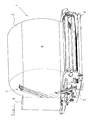
- This comprises a changing table device 3, on which a molded Erntegutballen 2 is located and about driven conveyor elements 4 during the Winding process is placed in a rotary motion.
- the wrapping web 5 is from taken from a supply roll 6.
- This supply roll 6 is on a winding body held, which - not shown in detail - circling around the bale 2 moves can be.
- the wrapping web 5 is a clamping device, generally designated 7 assigned to the also a separating element 8, which from the apparent in Fig. 1, essentially horizontally oriented inoperative position in the harnessverschwenkte operating position can be transferred is arranged.
- the Erntegutballen 2 is not yet in one Packaged state during the wrapping process.
- the clamping device the will be described in more detail below, is in an open state and the separator 8 in its inoperative position.
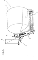
- the Erntegutballen 2 is substantially ready packed and the clamping device 7 is closed, while the wrapping web 5 has seized and a multilayer Folded web, leaving the wrapping sheet at about half its width or less reduced. In this state, the wrapping web 5 is passed through the clamping device 7 clamped.
- the changing table of the changing table device 3 is located in this final state of the winding process still in its horizontal envelope position.
- a state is shown, in which the wrapping or packaging material or the corresponding web has just been severed by the separating element 8.
- the clamping device 7 is kept firmly clamped, the separating element 8 is has shot up and has severed the Umsüllungsbahn, and that activated by the Changing table, which has acted on driver on the separator 8, while in his tilted unloading has been transferred, in the finished wrapped Harvest bales 2 can roll off the changing table.
- 5 and 6 is the Clamping device 7 shown with associated separating element 8 in more detail.
- the clamping device 7 has a movable in the illustrated embodiment Adjusting means in the form of a lifting cylinder 9. It also has a clamping element 10, which has at its rear end 11 a Bolzenschraubtagen 12 and in one slotted longitudinal guide 13 is guided in a housing, on which also the hydraulic cylinder 9 is supported.
- the clamping device 7 has in addition to the clamping element 10 is still a clamping bar 14, on which a driver 15 of the lifting cylinder 9 attacks.
- the lifting cylinder 9 is supported by a bolt 16 at 17 in the housing part 18.
- the clamping element 10th is in turn fork-shaped and cooperates with the clamping bar 14, which in turn has a clamping rail 19 which, with the interposition of spring elements 20 and 21 is mounted replaceably on the clamping bar.
- the forked Clamping element 10 can therefore the clamping rail 19 and partially the Clamping bar 14 overlap and in between a wrapping or packaging material web clamp on the clamping rail 19 when the lifting cylinder 9 in his extended position is brought, as shown in FIG. 5. In this position that is rear end 11 or the Bolzenschraubastic 12 of the clamping element 10th within the longitudinal guide 13 completely moved backwards, so that the clamping element 10 together with the clamping bar 14 assumes an approximately horizontal position.
- a force storage 22 in the form of a Compression spring provided.
- the energy storage 22 can be depressurized, the energy accumulator 22 can the Lift clamping element 10 into such an operating position or pivot slightly, in the clamping of the wrapping or packaging material no longer continue persists.
- the clamping element 10 is only one raise such area, as dictated by the deflection of the energy accumulator 22. Thereafter, the wrapping or packaging material from the clamping element 10th only managed, but no longer held tight.
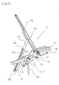
- Fig. 4 the hydraulic cylinder is shown retracted and thus has the driver 15 moves in the direction of the hydraulic cylinder 9, so that due to the pivoting Holder by the bolt 14.1 within the housing 18 of the clamping bar 14 together with the clamping rail 19, the spring elements 20 and 21 and the energy storage 22 is pivoted into the open position shown swung up. Due to its articulated connection at 23 with the clamping element 10 is this also pivoted in the pivoted-open position, under Attention of the end 11 and the Bolzenschraubtagen 12 in the slot guide 13.
Landscapes
- Life Sciences & Earth Sciences (AREA)
- Environmental Sciences (AREA)
- Basic Packing Technique (AREA)
- Storage Of Harvested Produce (AREA)
- Packaging Of Special Articles (AREA)
Abstract
Description
- Fig. 1
- ein Ausführungsbeispiel einer Vorrichtung nach der Erfindung mit einem auf einem Wickeltisch einer nicht näher dargestellten landwirtschaftlichen Erntemaschine gelegenen Erntegutballen im Verlaufe des Umhüllungsvorganges in einer perspektivischen Darstellung,
- Fig. 2
- das Ausführungsbeispiel nach Fig. 1 in einer perspektivischen Darstellung nach dem Ergreifen der Umhüllungs- bzw. Verpackungsmaterialbahn durch eine Klemmeinrichtung vor dem Abtrennen des Bahnmaterialabschnittes,
- Fig. 3
- das Ausführungsbeispiel nach Fig. 1 in einer Phase unmittelbar nach dem Durchtrennen der Umhüllungs- und Verpackungsmaterialbahn,
- Fig. 4
- ein Ausführungsbeispiel eines Klemmelementes in einer Darstellung gemäß Fig.1,
- Fig. 5
- das Ausführungsbeispiel des Klemmelementes in einer Darstellung gemäß Fig.2,
- Fig. 6
- das Ausführungsbeispiel des Klemmelementes in einer Darstellung gemäß Fig.3.
Claims (16)
- Vorrichtung zum Umhüllen oder Verpacken von insbesondere landwirtschaftlichen Erntegutballen mit einer Wickeleinheit und einer dieser zugeordneten Wickeltischeinrichtung (3) zur Aufnahme des Erntegutballens, wobei nach dem Umhüllen bzw. Verpacken des Erntegutballens eine Umhüllungs- oder Verpackungsmaterialbahn (5) mittels eines Trennelementes (8) beaufschlagbar ist, dadurch gekennzeichnet, dass das Trennelement (8) bewegbar abgestützt und aus einer Außerbetriebsstellung in eine die Umhüllungs- oder Verpackungsmaterialbahn (5) beaufschlagende Betriebsstellung überführbar ist.
- Vorrichtung nach Anspruch 1, dadurch gekennzeichnet, dass das Trennelement (8) verschwenkbar abgestützt ist.
- Vorrichtung nach Anspruch 1 oder 2, dadurch gekennzeichnet, dass das Trennelement (8) aus einer im wesentlichen horizontal ausgerichteten Außerbetriebsstellung in eine im wesentlichen aufrechten oder geneigt zur Vertikalen ausgerichteten Betriebsstellung überführbar ist.
- Vorrichtung nach einem der Ansprüche 1 bis 3, dadurch gekennzeichnet, dass das Trennelement (8) aus einer horizontalen Außerbetriebsstellung hin zu einer, von einem Wickelkörper zum, auf der Wickeltischeinrichtung (3) gelegenen Erntegutballen geführten Umhüllungs- oder Verpackungsmaterialbahn (5) gerichteten Bewegung in die Betriebsstellung überführbar ist.
- Vorrichtung nach einem der Ansprüche 1 bis 4, dadurch gekennzeichnet, dass die Wickeltischeinrichtung (3) beweglich ausgebildet ist und das Trennelement (8) für eine Überführung in die Betriebsstellung durch eine Bewegung der Wickeltischeinrichtung (4) aktivierbar ist.
- Vorrichtung nach Anspruch 5, dadurch gekennzeichnet, dass die Wickeltischeinrichtung (3) einen, in eine schräggestellte Entladestellung überführbaren Wickeltisch aufweist und das Trennelement (8) einen Mitnehmer (24) hat, der von dem Wickeltisch beaufschlagbar ist.
- Vorrichtung nach einem der Ansprüche 1 bis 6, dadurch gekennzeichnet, dass dem Trennelement (8) ein Klemmelement (10) mit einem Stellmittel (9) zugeordnet ist, das gegen die Kraft eines Kraftspeichers (22) in seine Klemmstellung überführbar und von dem Kraftspeicher (22) in eine außerhalb der Klemmstellung gelegene sowie von dem Kraftspeicher (22) vorgebbare Betriebsstellung bewegbar ist.
- Vorrichtung nach einem der Ansprüche 1 bis 7, dadurch gekennzeichnet, dass das Klemmelement (10) von dem Kraftspeicher (22) in einer Drucklosstellung des Stellmittels (9) in seine von dem Kraftspeicher (22) vorgebbare Betriebsstellung bewegbar ist.
- Vorrichtung nach einem der Ansprüche 1 bis 8, dadurch gekennzeichnet, dass der Kraftspeicher (22) als Druckfeder ausgebildet ist.
- Vorrichtung nach einem der Ansprüche 1 bis 9, dadurch gekennzeichnet, dass das Klemmelement (10) relativ zu einem den Kraftspeicher (22) tragenden Klemmbalken (14) bewegbar ist und eine Klemmzange ausgebildet.
- Vorrichtung nach einem der Ansprüche 1 bis 10, dadurch gekennzeichnet, dass das Klemmelement (10) einenends in einer Führung (13) geführt und in dieser translatorisch bewegbar ist.
- Vorrichtung nach einem der Ansprüche 1 bis 11, dadurch gekennzeichnet, dass das Klemmelement (10) von dem Stellmittel (9) in eine hochverschwenkte Öffnungsstellung und aus dieser von dem Stellmittel (9) in seine Klemmstellung überführbar ist.
- Vorrichtung nach einem der Ansprüche 1 bis 12, dadurch gekennzeichnet, dass das Klemmelement (10) über den Klemmbalken (14) in die hochverschwenkte Öffnungsstellung überführbar ist.
- Vorrichtung nach einem der Ansprüche 1 bis 13, dadurch gekennzeichnet, dass der Klemmbalken (14) und das Klemmelement (10) schnabelförmig auf und zu bewegbar sind und dass der Klemmbalken (14) eine elastisch abgestützte Klemmschiene trägt.
- Vorrichtung nach einem der Ansprüche 1 bis 14, dadurch gekennzeichnet, dass das Klemmelement (10) gabelförmig ausgebildet ist und den Klemmbalken (14) bereichsweise übergreift.
- Vorrichtung nach einem der Ansprüche 1 bis 15, dadurch gekennzeichnet, dass mittels des Klemmelementes (10) und des Klemmbalkens (14) bei ihrer Überführung aus der Öffnungsstellung in die Klemmstellung eine Faltung des Umhüllungs- oder Verpackungsmaterial erreichbar ist.
Applications Claiming Priority (2)
| Application Number | Priority Date | Filing Date | Title |
|---|---|---|---|
| DE10334678A DE10334678B4 (de) | 2003-07-30 | 2003-07-30 | Vorrichtung zum Umhüllen oder Verpacken von insbesondere landwirtschaftlichen Erntegutballen |
| DE10334678 | 2003-07-30 |
Publications (2)
| Publication Number | Publication Date |
|---|---|
| EP1502495A1 true EP1502495A1 (de) | 2005-02-02 |
| EP1502495B1 EP1502495B1 (de) | 2007-11-14 |
Family
ID=33521471
Family Applications (1)
| Application Number | Title | Priority Date | Filing Date |
|---|---|---|---|
| EP04017616A Expired - Lifetime EP1502495B1 (de) | 2003-07-30 | 2004-07-26 | Vorrichtung zum Umhüllen oder Verpacken von insbesondere landwirtschaftlichen Erntegutballen |
Country Status (3)
| Country | Link |
|---|---|
| EP (1) | EP1502495B1 (de) |
| AT (1) | ATE377932T1 (de) |
| DE (2) | DE10334678B4 (de) |
Cited By (5)
| Publication number | Priority date | Publication date | Assignee | Title |
|---|---|---|---|---|
| DE102005005651A1 (de) * | 2005-02-08 | 2006-08-17 | Welger Maschinenfabrik Gmbh | Klemmhalterung für den Anfang einer Materialbahn an Ballenumwickelvorrichtungen |
| DE102005005650A1 (de) * | 2005-02-08 | 2006-08-17 | Welger Maschinenfabrik Gmbh | Klemmhalterung für den Anfang einer Materialbahn an Ballenumwickelvorrichtungen |
| GB2513655A (en) * | 2013-05-03 | 2014-11-05 | Kuhn Geldrop Bv | Film Cutter |
| US9107346B2 (en) | 2009-05-29 | 2015-08-18 | Lely Patent N.V. | Wrapping device |
| US9560807B2 (en) | 2009-05-29 | 2017-02-07 | Lely Patent N.V. | Wrapping device and method for wrapping an object |
Families Citing this family (1)
| Publication number | Priority date | Publication date | Assignee | Title |
|---|---|---|---|---|
| DE102007051491A1 (de) | 2007-10-27 | 2009-04-30 | Welger Maschinenfabrik Gmbh | Vorrichtung zum Umwickeln von Körpern mit einer Folienbahn |
Citations (5)
| Publication number | Priority date | Publication date | Assignee | Title |
|---|---|---|---|---|
| EP0367529A1 (de) * | 1988-10-31 | 1990-05-09 | Kverneland Underhaug A/S | Automatische Umhüllvorrichtung für Rundballen |
| GB2249077A (en) * | 1990-09-19 | 1992-04-29 | Wellmount Ltd | Bale wrapping apparatus |
| FR2679105A1 (fr) * | 1991-07-17 | 1993-01-22 | Doucet Freres | Machine a emballer des balles rondes de fourrage. |
| DE4404225A1 (de) | 1993-02-15 | 1994-08-18 | Kverneland Underhaug As | Ballen-Umwicklungsvorrichtung |
| US5822967A (en) * | 1996-06-11 | 1998-10-20 | Vermeer Manufacturing Co. | Baler with swing arm bale wrapper |
Family Cites Families (1)
| Publication number | Priority date | Publication date | Assignee | Title |
|---|---|---|---|---|
| DE19542618C2 (de) * | 1995-11-15 | 2001-05-31 | Friatec Rpp Gmbh System Altvat | Folienwickelvorrichtung |
-
2003
- 2003-07-30 DE DE10334678A patent/DE10334678B4/de not_active Expired - Fee Related
-
2004
- 2004-07-26 AT AT04017616T patent/ATE377932T1/de active
- 2004-07-26 EP EP04017616A patent/EP1502495B1/de not_active Expired - Lifetime
- 2004-07-26 DE DE502004005470T patent/DE502004005470D1/de not_active Expired - Lifetime
Patent Citations (5)
| Publication number | Priority date | Publication date | Assignee | Title |
|---|---|---|---|---|
| EP0367529A1 (de) * | 1988-10-31 | 1990-05-09 | Kverneland Underhaug A/S | Automatische Umhüllvorrichtung für Rundballen |
| GB2249077A (en) * | 1990-09-19 | 1992-04-29 | Wellmount Ltd | Bale wrapping apparatus |
| FR2679105A1 (fr) * | 1991-07-17 | 1993-01-22 | Doucet Freres | Machine a emballer des balles rondes de fourrage. |
| DE4404225A1 (de) | 1993-02-15 | 1994-08-18 | Kverneland Underhaug As | Ballen-Umwicklungsvorrichtung |
| US5822967A (en) * | 1996-06-11 | 1998-10-20 | Vermeer Manufacturing Co. | Baler with swing arm bale wrapper |
Cited By (8)
| Publication number | Priority date | Publication date | Assignee | Title |
|---|---|---|---|---|
| DE102005005651A1 (de) * | 2005-02-08 | 2006-08-17 | Welger Maschinenfabrik Gmbh | Klemmhalterung für den Anfang einer Materialbahn an Ballenumwickelvorrichtungen |
| DE102005005650A1 (de) * | 2005-02-08 | 2006-08-17 | Welger Maschinenfabrik Gmbh | Klemmhalterung für den Anfang einer Materialbahn an Ballenumwickelvorrichtungen |
| DE102005005651B4 (de) | 2005-02-08 | 2014-08-21 | Lely Vermeer Maschinenfabrik GmbH | Klemmhalterung für den Anfang einer Materialbahn an Ballenumwickelvorrichtungen |
| US9107346B2 (en) | 2009-05-29 | 2015-08-18 | Lely Patent N.V. | Wrapping device |
| US9560807B2 (en) | 2009-05-29 | 2017-02-07 | Lely Patent N.V. | Wrapping device and method for wrapping an object |
| US9930835B2 (en) | 2009-05-29 | 2018-04-03 | Lely Patent N.V. | Wrapping device |
| GB2513655A (en) * | 2013-05-03 | 2014-11-05 | Kuhn Geldrop Bv | Film Cutter |
| EP2798946A1 (de) * | 2013-05-03 | 2014-11-05 | Kuhn-Geldrop B.V. | Folienschneider |
Also Published As
| Publication number | Publication date |
|---|---|
| DE502004005470D1 (de) | 2007-12-27 |
| ATE377932T1 (de) | 2007-11-15 |
| EP1502495B1 (de) | 2007-11-14 |
| DE10334678B4 (de) | 2005-10-20 |
| DE10334678A1 (de) | 2005-03-03 |
Similar Documents
| Publication | Publication Date | Title |
|---|---|---|
| EP0075252B1 (de) | Automatische Bindeeinrichtung für Maschinen zum Herstellen von zylindrischen Ballen aus Erntegut in einer Wickelkammer | |
| DE3418681A1 (de) | Rollballenpresse fuer landwirtschaftliche halmgueter mit einer huellvorrichtung | |
| EP4108069B1 (de) | Rundballenpresse | |
| DE2166983B2 (de) | Chirurgisches Instrument zum Herumlegen von Klammern zum Abbinden rohrförmiger organischer Gebilde | |
| DE3414080A1 (de) | Vorrichtung zum binden von rollballen aus landwirtschaftlichem erntegut | |
| DE8915767U1 (de) | Automatische Rundballen-Umwickelvorrichtung | |
| DE69015338T2 (de) | Ballenumwickelvorrichtung für Rundballenpressen. | |
| DE3617155C2 (de) | ||
| EP1502495B1 (de) | Vorrichtung zum Umhüllen oder Verpacken von insbesondere landwirtschaftlichen Erntegutballen | |
| DE202016004710U1 (de) | Ballenwickler | |
| WO1986001974A1 (fr) | Procede et dispositif pour la confection de bottes a partir de vegetaux coupes | |
| DE4211518C2 (de) | Schneidwerk | |
| DE2530320A1 (de) | Bindevorrichtung fuer wickelballenpressen | |
| EP1308080A2 (de) | Bindevorrichtung für eine Rundballenpresse | |
| EP1502494B1 (de) | Vorrichtung zum Umhüllen oder Verpacken von insbesondere landwirtschaftlichen Erntegutballen | |
| EP3395159B1 (de) | Ballenpresse | |
| DE102018112843A1 (de) | Ballenpresse und Verfahren zum Betreiben einer Ballenpresse | |
| EP0464651B1 (de) | Grossballenpresse | |
| DE1786472C3 (de) | Verfahren und Vorrichtung zum Etikettieren von Aufgußbeuteln | |
| EP3391733B1 (de) | Ballenpresse | |
| DE202005018176U1 (de) | Vorrichtung zum Bündeln von Gegenständen | |
| EP3391729B1 (de) | Ballenpresse | |
| DE102021130290A1 (de) | Rundballenpresse | |
| DE19720542A1 (de) | Vorrichtung und Verfahren zur Sicherung von Garnenden | |
| DE19607508C1 (de) | Auspackmaschine für Rollen, insbes. Druckpapierrollen |
Legal Events
| Date | Code | Title | Description |
|---|---|---|---|
| PUAI | Public reference made under article 153(3) epc to a published international application that has entered the european phase |
Free format text: ORIGINAL CODE: 0009012 |
|
| AK | Designated contracting states |
Kind code of ref document: A1 Designated state(s): AT BE BG CH CY CZ DE DK EE ES FI FR GB GR HU IE IT LI LU MC NL PL PT RO SE SI SK TR |
|
| AX | Request for extension of the european patent |
Extension state: AL HR LT LV MK |
|
| 17P | Request for examination filed |
Effective date: 20050718 |
|
| AKX | Designation fees paid |
Designated state(s): AT BE BG CH CY CZ DE DK EE ES FI FR GB GR HU IE IT LI LU MC NL PL PT RO SE SI SK TR |
|
| GRAP | Despatch of communication of intention to grant a patent |
Free format text: ORIGINAL CODE: EPIDOSNIGR1 |
|
| GRAS | Grant fee paid |
Free format text: ORIGINAL CODE: EPIDOSNIGR3 |
|
| GRAA | (expected) grant |
Free format text: ORIGINAL CODE: 0009210 |
|
| AK | Designated contracting states |
Kind code of ref document: B1 Designated state(s): AT BE BG CH CY CZ DE DK EE ES FI FR GB GR HU IE IT LI LU MC NL PL PT RO SE SI SK TR |
|
| REG | Reference to a national code |
Ref country code: GB Ref legal event code: FG4D Free format text: NOT ENGLISH |
|
| RIN1 | Information on inventor provided before grant (corrected) |
Inventor name: SCHULZ, STEPHAN Inventor name: VAN BASSEN, ALOYS Inventor name: KRONE, BERNARD, DR.-ING. E.H. |
|
| REG | Reference to a national code |
Ref country code: CH Ref legal event code: EP |
|
| REG | Reference to a national code |
Ref country code: IE Ref legal event code: FG4D Free format text: LANGUAGE OF EP DOCUMENT: GERMAN |
|
| REF | Corresponds to: |
Ref document number: 502004005470 Country of ref document: DE Date of ref document: 20071227 Kind code of ref document: P |
|
| REG | Reference to a national code |
Ref country code: DE Ref legal event code: R096 Ref document number: 502004005470 Country of ref document: DE Effective date: 20071227 |
|
| PG25 | Lapsed in a contracting state [announced via postgrant information from national office to epo] |
Ref country code: SE Free format text: LAPSE BECAUSE OF FAILURE TO SUBMIT A TRANSLATION OF THE DESCRIPTION OR TO PAY THE FEE WITHIN THE PRESCRIBED TIME-LIMIT Effective date: 20080214 Ref country code: ES Free format text: LAPSE BECAUSE OF FAILURE TO SUBMIT A TRANSLATION OF THE DESCRIPTION OR TO PAY THE FEE WITHIN THE PRESCRIBED TIME-LIMIT Effective date: 20080225 |
|
| PG25 | Lapsed in a contracting state [announced via postgrant information from national office to epo] |
Ref country code: SI Free format text: LAPSE BECAUSE OF FAILURE TO SUBMIT A TRANSLATION OF THE DESCRIPTION OR TO PAY THE FEE WITHIN THE PRESCRIBED TIME-LIMIT Effective date: 20071114 Ref country code: PL Free format text: LAPSE BECAUSE OF FAILURE TO SUBMIT A TRANSLATION OF THE DESCRIPTION OR TO PAY THE FEE WITHIN THE PRESCRIBED TIME-LIMIT Effective date: 20071114 Ref country code: BG Free format text: LAPSE BECAUSE OF FAILURE TO SUBMIT A TRANSLATION OF THE DESCRIPTION OR TO PAY THE FEE WITHIN THE PRESCRIBED TIME-LIMIT Effective date: 20080214 |
|
| GBV | Gb: ep patent (uk) treated as always having been void in accordance with gb section 77(7)/1977 [no translation filed] | ||
| PG25 | Lapsed in a contracting state [announced via postgrant information from national office to epo] |
Ref country code: DK Free format text: LAPSE BECAUSE OF FAILURE TO SUBMIT A TRANSLATION OF THE DESCRIPTION OR TO PAY THE FEE WITHIN THE PRESCRIBED TIME-LIMIT Effective date: 20071114 Ref country code: CZ Free format text: LAPSE BECAUSE OF FAILURE TO SUBMIT A TRANSLATION OF THE DESCRIPTION OR TO PAY THE FEE WITHIN THE PRESCRIBED TIME-LIMIT Effective date: 20071114 |
|
| ET | Fr: translation filed | ||
| PG25 | Lapsed in a contracting state [announced via postgrant information from national office to epo] |
Ref country code: RO Free format text: LAPSE BECAUSE OF FAILURE TO SUBMIT A TRANSLATION OF THE DESCRIPTION OR TO PAY THE FEE WITHIN THE PRESCRIBED TIME-LIMIT Effective date: 20071114 Ref country code: SK Free format text: LAPSE BECAUSE OF FAILURE TO SUBMIT A TRANSLATION OF THE DESCRIPTION OR TO PAY THE FEE WITHIN THE PRESCRIBED TIME-LIMIT Effective date: 20071114 |
|
| PLBE | No opposition filed within time limit |
Free format text: ORIGINAL CODE: 0009261 |
|
| STAA | Information on the status of an ep patent application or granted ep patent |
Free format text: STATUS: NO OPPOSITION FILED WITHIN TIME LIMIT |
|
| PG25 | Lapsed in a contracting state [announced via postgrant information from national office to epo] |
Ref country code: PT Free format text: LAPSE BECAUSE OF FAILURE TO SUBMIT A TRANSLATION OF THE DESCRIPTION OR TO PAY THE FEE WITHIN THE PRESCRIBED TIME-LIMIT Effective date: 20080414 |
|
| 26N | No opposition filed |
Effective date: 20080815 |
|
| PG25 | Lapsed in a contracting state [announced via postgrant information from national office to epo] |
Ref country code: GB Free format text: LAPSE BECAUSE OF FAILURE TO SUBMIT A TRANSLATION OF THE DESCRIPTION OR TO PAY THE FEE WITHIN THE PRESCRIBED TIME-LIMIT Effective date: 20071114 |
|
| REG | Reference to a national code |
Ref country code: DE Ref legal event code: R097 Ref document number: 502004005470 Country of ref document: DE Effective date: 20080815 |
|
| PG25 | Lapsed in a contracting state [announced via postgrant information from national office to epo] |
Ref country code: GR Free format text: LAPSE BECAUSE OF FAILURE TO SUBMIT A TRANSLATION OF THE DESCRIPTION OR TO PAY THE FEE WITHIN THE PRESCRIBED TIME-LIMIT Effective date: 20080215 |
|
| REG | Reference to a national code |
Ref country code: CH Ref legal event code: PL |
|
| PG25 | Lapsed in a contracting state [announced via postgrant information from national office to epo] |
Ref country code: MC Free format text: LAPSE BECAUSE OF NON-PAYMENT OF DUE FEES Effective date: 20080731 |
|
| PG25 | Lapsed in a contracting state [announced via postgrant information from national office to epo] |
Ref country code: EE Free format text: LAPSE BECAUSE OF FAILURE TO SUBMIT A TRANSLATION OF THE DESCRIPTION OR TO PAY THE FEE WITHIN THE PRESCRIBED TIME-LIMIT Effective date: 20071114 |
|
| PG25 | Lapsed in a contracting state [announced via postgrant information from national office to epo] |
Ref country code: LI Free format text: LAPSE BECAUSE OF NON-PAYMENT OF DUE FEES Effective date: 20080731 Ref country code: CH Free format text: LAPSE BECAUSE OF NON-PAYMENT OF DUE FEES Effective date: 20080731 |
|
| PG25 | Lapsed in a contracting state [announced via postgrant information from national office to epo] |
Ref country code: CY Free format text: LAPSE BECAUSE OF FAILURE TO SUBMIT A TRANSLATION OF THE DESCRIPTION OR TO PAY THE FEE WITHIN THE PRESCRIBED TIME-LIMIT Effective date: 20071114 |
|
| PG25 | Lapsed in a contracting state [announced via postgrant information from national office to epo] |
Ref country code: LU Free format text: LAPSE BECAUSE OF NON-PAYMENT OF DUE FEES Effective date: 20080726 Ref country code: HU Free format text: LAPSE BECAUSE OF FAILURE TO SUBMIT A TRANSLATION OF THE DESCRIPTION OR TO PAY THE FEE WITHIN THE PRESCRIBED TIME-LIMIT Effective date: 20080515 |
|
| PG25 | Lapsed in a contracting state [announced via postgrant information from national office to epo] |
Ref country code: TR Free format text: LAPSE BECAUSE OF FAILURE TO SUBMIT A TRANSLATION OF THE DESCRIPTION OR TO PAY THE FEE WITHIN THE PRESCRIBED TIME-LIMIT Effective date: 20071114 |
|
| REG | Reference to a national code |
Ref country code: FR Ref legal event code: PLFP Year of fee payment: 13 |
|
| REG | Reference to a national code |
Ref country code: FR Ref legal event code: PLFP Year of fee payment: 14 |
|
| REG | Reference to a national code |
Ref country code: FR Ref legal event code: PLFP Year of fee payment: 15 |
|
| REG | Reference to a national code |
Ref country code: BE Ref legal event code: HC Owner name: MASCHINENFABRIK BERNARD KRONE GMBH & CO. KG; DE Free format text: DETAILS ASSIGNMENT: CHANGE OF OWNER(S), CHANGE OF OWNER(S) NAME Effective date: 20210209 |
|
| REG | Reference to a national code |
Ref country code: DE Ref legal event code: R081 Ref document number: 502004005470 Country of ref document: DE Owner name: KRONE AGRICULTURE SE, DE Free format text: FORMER OWNER: MASCHINENFABRIK BERNARD KRONE GMBH, 48480 SPELLE, DE |
|
| REG | Reference to a national code |
Ref country code: FI Ref legal event code: PCE Owner name: KRONE AGRICULTURE SE |
|
| REG | Reference to a national code |
Ref country code: DE Ref legal event code: R084 Ref document number: 502004005470 Country of ref document: DE |
|
| REG | Reference to a national code |
Ref country code: AT Ref legal event code: PC Ref document number: 377932 Country of ref document: AT Kind code of ref document: T Owner name: KRONE AGRICULTURE SE, DE Effective date: 20211022 |
|
| REG | Reference to a national code |
Ref country code: NL Ref legal event code: PD Owner name: KRONE AGRICULTURE SE; DE Free format text: DETAILS ASSIGNMENT: CHANGE OF OWNER(S), MERGE; FORMER OWNER NAME: MASCHINENFABRIK KRONE BETEILIGUNGS-GMBH Effective date: 20211126 Ref country code: NL Ref legal event code: HC Owner name: MASCHINENFABRIK KRONE BETEILIGUNGS-GMBH; DE Free format text: DETAILS ASSIGNMENT: CHANGE OF OWNER(S), CHANGE OF OWNER(S) NAME; FORMER OWNER NAME: MASCHINENFABRIK BERNARD KRONE GMBH Effective date: 20211126 |
|
| PGFP | Annual fee paid to national office [announced via postgrant information from national office to epo] |
Ref country code: NL Payment date: 20220720 Year of fee payment: 19 |
|
| PGFP | Annual fee paid to national office [announced via postgrant information from national office to epo] |
Ref country code: IT Payment date: 20220729 Year of fee payment: 19 Ref country code: IE Payment date: 20220720 Year of fee payment: 19 Ref country code: FI Payment date: 20220719 Year of fee payment: 19 Ref country code: DE Payment date: 20220621 Year of fee payment: 19 Ref country code: AT Payment date: 20220718 Year of fee payment: 19 |
|
| PGFP | Annual fee paid to national office [announced via postgrant information from national office to epo] |
Ref country code: FR Payment date: 20220727 Year of fee payment: 19 Ref country code: BE Payment date: 20220720 Year of fee payment: 19 |
|
| P01 | Opt-out of the competence of the unified patent court (upc) registered |
Effective date: 20230517 |
|
| REG | Reference to a national code |
Ref country code: DE Ref legal event code: R119 Ref document number: 502004005470 Country of ref document: DE |
|
| REG | Reference to a national code |
Ref country code: NL Ref legal event code: MM Effective date: 20230801 |
|
| REG | Reference to a national code |
Ref country code: AT Ref legal event code: MM01 Ref document number: 377932 Country of ref document: AT Kind code of ref document: T Effective date: 20230726 |
|
| REG | Reference to a national code |
Ref country code: BE Ref legal event code: MM Effective date: 20230731 |
|
| PG25 | Lapsed in a contracting state [announced via postgrant information from national office to epo] |
Ref country code: NL Free format text: LAPSE BECAUSE OF NON-PAYMENT OF DUE FEES Effective date: 20230801 |
|
| PG25 | Lapsed in a contracting state [announced via postgrant information from national office to epo] |
Ref country code: AT Free format text: LAPSE BECAUSE OF NON-PAYMENT OF DUE FEES Effective date: 20230726 |
|
| REG | Reference to a national code |
Ref country code: IE Ref legal event code: MM4A |
|
| PG25 | Lapsed in a contracting state [announced via postgrant information from national office to epo] |
Ref country code: NL Free format text: LAPSE BECAUSE OF NON-PAYMENT OF DUE FEES Effective date: 20230801 Ref country code: FI Free format text: LAPSE BECAUSE OF NON-PAYMENT OF DUE FEES Effective date: 20230726 Ref country code: DE Free format text: LAPSE BECAUSE OF NON-PAYMENT OF DUE FEES Effective date: 20240201 Ref country code: AT Free format text: LAPSE BECAUSE OF NON-PAYMENT OF DUE FEES Effective date: 20230726 |
|
| PG25 | Lapsed in a contracting state [announced via postgrant information from national office to epo] |
Ref country code: FR Free format text: LAPSE BECAUSE OF NON-PAYMENT OF DUE FEES Effective date: 20230731 Ref country code: BE Free format text: LAPSE BECAUSE OF NON-PAYMENT OF DUE FEES Effective date: 20230731 |
|
| PG25 | Lapsed in a contracting state [announced via postgrant information from national office to epo] |
Ref country code: IE Free format text: LAPSE BECAUSE OF NON-PAYMENT OF DUE FEES Effective date: 20230726 |
|
| PG25 | Lapsed in a contracting state [announced via postgrant information from national office to epo] |
Ref country code: IT Free format text: LAPSE BECAUSE OF NON-PAYMENT OF DUE FEES Effective date: 20230726 Ref country code: IE Free format text: LAPSE BECAUSE OF NON-PAYMENT OF DUE FEES Effective date: 20230726 |