EP1502272B1 - Commutateur electrique a systeme de refroidissement - Google Patents
Commutateur electrique a systeme de refroidissement Download PDFInfo
- Publication number
- EP1502272B1 EP1502272B1 EP03735261A EP03735261A EP1502272B1 EP 1502272 B1 EP1502272 B1 EP 1502272B1 EP 03735261 A EP03735261 A EP 03735261A EP 03735261 A EP03735261 A EP 03735261A EP 1502272 B1 EP1502272 B1 EP 1502272B1
- Authority
- EP
- European Patent Office
- Prior art keywords
- switching device
- tubular
- fitting
- electrical switching
- cooling
- Prior art date
- Legal status (The legal status is an assumption and is not a legal conclusion. Google has not performed a legal analysis and makes no representation as to the accuracy of the status listed.)
- Expired - Lifetime
Links
- 238000001816 cooling Methods 0.000 title claims abstract description 47
- 239000007787 solid Substances 0.000 claims description 22
- 238000010791 quenching Methods 0.000 claims description 9
- 230000000171 quenching effect Effects 0.000 claims description 9
- 238000010276 construction Methods 0.000 description 4
- 230000000694 effects Effects 0.000 description 4
- 230000007423 decrease Effects 0.000 description 1
- 230000001419 dependent effect Effects 0.000 description 1
- 238000006073 displacement reaction Methods 0.000 description 1
- 239000004744 fabric Substances 0.000 description 1
- 230000002349 favourable effect Effects 0.000 description 1
- 238000009434 installation Methods 0.000 description 1
- 239000011810 insulating material Substances 0.000 description 1
- 238000004519 manufacturing process Methods 0.000 description 1
- 238000000034 method Methods 0.000 description 1
Images
Classifications
-
- H—ELECTRICITY
- H01—ELECTRIC ELEMENTS
- H01H—ELECTRIC SWITCHES; RELAYS; SELECTORS; EMERGENCY PROTECTIVE DEVICES
- H01H33/00—High-tension or heavy-current switches with arc-extinguishing or arc-preventing means
- H01H33/70—Switches with separate means for directing, obtaining, or increasing flow of arc-extinguishing fluid
- H01H33/7015—Switches with separate means for directing, obtaining, or increasing flow of arc-extinguishing fluid characterised by flow directing elements associated with contacts
-
- H—ELECTRICITY
- H01—ELECTRIC ELEMENTS
- H01H—ELECTRIC SWITCHES; RELAYS; SELECTORS; EMERGENCY PROTECTIVE DEVICES
- H01H33/00—High-tension or heavy-current switches with arc-extinguishing or arc-preventing means
- H01H33/70—Switches with separate means for directing, obtaining, or increasing flow of arc-extinguishing fluid
- H01H33/88—Switches with separate means for directing, obtaining, or increasing flow of arc-extinguishing fluid the flow of arc-extinguishing fluid being produced or increased by movement of pistons or other pressure-producing parts
- H01H33/90—Switches with separate means for directing, obtaining, or increasing flow of arc-extinguishing fluid the flow of arc-extinguishing fluid being produced or increased by movement of pistons or other pressure-producing parts this movement being effected by or in conjunction with the contact-operating mechanism
- H01H33/91—Switches with separate means for directing, obtaining, or increasing flow of arc-extinguishing fluid the flow of arc-extinguishing fluid being produced or increased by movement of pistons or other pressure-producing parts this movement being effected by or in conjunction with the contact-operating mechanism the arc-extinguishing fluid being air or gas
-
- H—ELECTRICITY
- H01—ELECTRIC ELEMENTS
- H01H—ELECTRIC SWITCHES; RELAYS; SELECTORS; EMERGENCY PROTECTIVE DEVICES
- H01H9/00—Details of switching devices, not covered by groups H01H1/00 - H01H7/00
- H01H9/52—Cooling of switch parts
- H01H2009/526—Cooling of switch parts of the high voltage switches
-
- H—ELECTRICITY
- H01—ELECTRIC ELEMENTS
- H01H—ELECTRIC SWITCHES; RELAYS; SELECTORS; EMERGENCY PROTECTIVE DEVICES
- H01H33/00—High-tension or heavy-current switches with arc-extinguishing or arc-preventing means
- H01H33/70—Switches with separate means for directing, obtaining, or increasing flow of arc-extinguishing fluid
- H01H33/88—Switches with separate means for directing, obtaining, or increasing flow of arc-extinguishing fluid the flow of arc-extinguishing fluid being produced or increased by movement of pistons or other pressure-producing parts
- H01H2033/888—Deflection of hot gasses and arcing products
-
- H—ELECTRICITY
- H01—ELECTRIC ELEMENTS
- H01H—ELECTRIC SWITCHES; RELAYS; SELECTORS; EMERGENCY PROTECTIVE DEVICES
- H01H9/00—Details of switching devices, not covered by groups H01H1/00 - H01H7/00
- H01H9/52—Cooling of switch parts
Definitions
- the invention relates to an electrical switching device, which in the course of a switch-off an extinguishing gas flow causes, with a passage openings for the quenching gas flow having massive wall of a cooling device.
- Such an electrical switching device is, for example from US Pat. No. 4,328,403.
- the local electrical Switching device has a switching path, in which by an arc caused quenching gas is generated.
- This Extinguishing gas flows through a channel into a cooling device, which is designed as a cooling tube.
- This cooling tube has a massive wall, in which several openings are introduced to the passage of the quenching gas flow.
- the Cooling device continues to a cooling fabric (mesh cooler), which is arranged in the interior of the insulating tube and partially the passage openings covered.
- the cooling effect of such a cooling tube is dependent on the number and the cross section of the massive wall introduced passages. Depending on the desired cooling effect It is therefore necessary to have a different number of passages to introduce into the cooling tube.
- the cooling power to be provided by the cooling device is essentially by the construction of the electric Switching device set. Changes in the construction of the electrical switching device therefore draw forcibly adjustments the cooling device with regard to their cooling capacity after himself. This affects in particular the type and number as well the arrangement of the passage openings.
- the present invention is based on the object, the a solid wall having cooling means of an electrical Form switching device such that a simplified Adjustment of the cooling capacity of the cooling device allows is.
- the task is in an electrical switching device with a Cooling device of the type mentioned according to the invention solved in that at least one of the passage openings by means of a releasably connected to the cooling device socket fitting is closable.
- To control the cooling capacity of the cooling devices is at least one of the passage openings closed.
- a standard body with arranged to use through openings and this ever according to the structural conditions of the electrical switching device adapt so that a desired cooling behavior can be achieved is.
- By combining the closure effect with a suitable socket fitting it is possible to use the massive Wall as well as openings in the massive Wall to close through the socket fitting.
- By the detachable connection of cooling device and socket fitting There are advantages in terms of mounting the cooling device in the electrical switching device. Furthermore you can different with a small number of basic elements Cooling devices premounted with different cooling capacities become. As a result, a complex posture is varied Cooling facilities lapsed.
- An advantageous embodiment may further provide that the socket fitting the cooling device at least partially fixed.
- the socket fitting in addition to the fixation of the cooling device area is extended to at least one of the To close passage openings.
- the massive Wall is tubular.
- a tubular wall provides a dielectrically advantageous Entities in which in a large area through openings can be arranged. At a relatively small Construction volume is such a great cooling performance achievable.
- a further advantageous embodiment provides that the Socket fitting on the outside of the tubular solid Wall is arranged.
- the socket fitting In an arrangement of the socket fitting on the outside remains the inner region of the tubular solid wall free of additional installations. This is the flow of the Extinguishing gas on the inside of the tubular wall not with special needs. Furthermore, the socket fitting is on the outside the tubular solid wall in a simple way and Way mountable.
- the socket fitting the tubular solid wall at one end in full includes.
- the socket fitting closes the tubular wall at one Ends and holds the wall, without the extent strongly enlarge.
- the tubular wall is in small volume to install electrical switching devices in a simple manner and position it there.
- By embracing the Full scope still results in a good mechanical Support of the solid wall in the socket fitting. occurring Holding forces are thus distributed over a large area.
- socket fitting a final version for the tubular solid wall in the form of a Tube socket forms and that the socket fitting to a Middle section of the tubular massive wall continues is more extensive than necessary for the mechanical holding function.
- a pipe socket forms a particularly advantageous embodiment variant for the fitting fitting.
- Pipe stubs are special easy to manufacture and with the tubular solid Wall connectable.
- a perforated plate can be produced in a particularly favorable manner.
- a tubular solid wall is a tube easily made from the perforated plate.
- the socket fitting is it possible to form the tube such that the perforated plate in the Area of the pipe seam is formed overlapping and through the socket fitting is held in the tube shape. This is it is not necessary, the perforated plate itself, for example by means of Welds to keep in the tube shape.
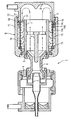
- the figure shows an electrical switching device 1, namely a High-voltage circuit breaker in a schematic representation.
- the electrical switching device 1 is within a filled with an insulating gas not shown in the figure Housing arranged.
- the electrical switching device 1 has a movable arcing contact 2 and a fixed Arc contact piece 3 on. Coaxial to the arcing contact 2 and the opposite thereto movable fixed contact piece 3 are a movable rated current contact piece 4 and a fixed arcing contact piece 5 arranged.
- a switching process occurs at the arcing contact pieces 2 and 3 on an arc. Because of this Arc is in the area of the two arcing contact pieces 2, 3 surrounding insulating nozzle 6 an extinguishing gas generated.
- This quenching gas flows to a part of the insulating material 6 in the direction of the fixed arcing contact piece 3 off.
- the fixed arcing contact piece 3 is surrounded by a tubular channel 7.
- the first flow deflection device 8 directs the quenching gas flow to the outside of the tubular Channel 7.
- the first flow diverter 8 is part a support housing 9.
- the support housing 9 has a radial Opening 10.
- the radial opening 10 is annular in circumference educated.
- the radial opening 10 is by means of a covered second tubular deflecting device 11. Between the second deflecting device 11 and the first deflecting device 8, an outflow opening 12 is formed, through which the quenching gas can escape.
- a tubular solid wall 13 of a cooling device In the region of the radial opening 10 is in the flow path of the Extinguishing gas a tubular solid wall 13 of a cooling device arranged.
- the tubular solid wall 13 has a plurality of passage openings 14a, b, c. At one first end of the tubular solid wall 13, this is in an annular groove 15 mounted.
- a pipe socket 16 is arranged.
- the pipe socket 16 acts as a socket fitting and surrounds the tubular massive wall 13 in full.
- the pipe socket 16 has a radially inwardly directed stop 17th on, which is a postponement of the pipe socket 16 on the limited tubular massive wall 13.
- the tubular massive wall 13 shown in the figure can be advantageously formed of a perforated plate.
- the perforated plate to bend into a tubular shape, with the Overlap the ends of the perforated plate.
- the tubular massive Wall 13 elastically self-holding in the annular groove 15 and the pipe socket 16 inserted.
Landscapes
- Arc-Extinguishing Devices That Are Switches (AREA)
- Circuit Breakers (AREA)
- Switch Cases, Indication, And Locking (AREA)
- Cooling Or The Like Of Electrical Apparatus (AREA)
Abstract
Claims (8)
- Appareil (1) électrique de coupure qui provoque, au cours d'un mouvement de déconnexion, un courant de gaz d'extinction, comprenant une paroi (13) massive d'un dispositif de refroidissement ayant des ouvertures (14a,b,c) de passage du courant de gaz d'extinction, caractérisé en ce qu'au moins l'une des ouvertures (14c) de passage peut être obtenue au moyen d'une armature (16) de prise assemblée de manière amovible au dispositif de refroidissement.
- Appareil (1) électrique de coupure suivant la revendication 1, caractérisé en ce que l'armature (16) de prise immobilise le dispositif de refroidissement au moins en partie.
- Appareil (1) électrique de coupure suivant la revendication 2, caractérisé en ce que l'armature (16) de prise s'étend en outre au-delà de la partie nécessaire à l'immobilisation du dispositif de refroidissement pour obturer au moins l'une des ouvertures (14c) de passage.
- Appareil (1) électrique de coupure suivant l'une des revendications 1 à 3, caractérisé en ce que la paroi (13) massive est tubulaire.
- Appareil (1) électrique de coupure suivant la revendication 4, caractérisé en ce que l'armature (16) de prise est disposée du côté extérieur de la paroi (13) massive tubulaire.
- Appareil (1) électrique de coupure suivant l'une des revendications 4 ou 5, caractérisé en ce que l'armature (16) de prise entoure la paroi (13) massive tubulaire complètement à une extrémité.
- Appareil (1) électrique de coupure suivant la revendication 6, caractérisé en ce que l'armature (16) de prise forme une prise d'extrémité pour la paroi (13) massive tubulaire sous la forme d'un raccord tubulaire, et en ce que l'armature (16) de prise s'étend vers une partie médiane de la paroi (13) massive tubulaire plus que ce qui est nécessaire pour la fonction de maintien mécanique.
- Appareil (1) électrique de coupure suivant l'une des revendications 1 à 7, caractérisé en ce que la paroi (13) massive ayant des ouvertures (14a,b,c) de passage est formée par une tôle perforée.
Applications Claiming Priority (3)
| Application Number | Priority Date | Filing Date | Title |
|---|---|---|---|
| DE10221576A DE10221576B4 (de) | 2002-05-08 | 2002-05-08 | Elektrisches Schaltgerät mit einer Kühleinrichtung |
| DE10221576 | 2002-05-08 | ||
| PCT/DE2003/001260 WO2003096366A1 (fr) | 2002-05-08 | 2003-04-10 | Commutateur electrique a systeme de refroidissement |
Publications (2)
| Publication Number | Publication Date |
|---|---|
| EP1502272A1 EP1502272A1 (fr) | 2005-02-02 |
| EP1502272B1 true EP1502272B1 (fr) | 2005-11-23 |
Family
ID=29413839
Family Applications (1)
| Application Number | Title | Priority Date | Filing Date |
|---|---|---|---|
| EP03735261A Expired - Lifetime EP1502272B1 (fr) | 2002-05-08 | 2003-04-10 | Commutateur electrique a systeme de refroidissement |
Country Status (6)
| Country | Link |
|---|---|
| US (1) | US20050150868A1 (fr) |
| EP (1) | EP1502272B1 (fr) |
| CN (1) | CN1293585C (fr) |
| DE (2) | DE10221576B4 (fr) |
| RU (1) | RU2309477C2 (fr) |
| WO (1) | WO2003096366A1 (fr) |
Families Citing this family (18)
| Publication number | Priority date | Publication date | Assignee | Title |
|---|---|---|---|---|
| DE502004004571D1 (de) * | 2004-06-07 | 2007-09-20 | Abb Technology Ag | Leistungsschalter |
| DE502005009041D1 (de) | 2005-09-26 | 2010-04-01 | Abb Technology Ag | Hochspannungsschalter mit verbesserter Schaltleistung |
| FR2896083B1 (fr) * | 2006-01-06 | 2009-07-10 | Areva T & D Sa | Echappement de gaz pour disjoncteur |
| DE502006009434D1 (de) | 2006-03-14 | 2011-06-16 | Abb Technology Ag | Schaltkammer für einen gasisolierten Hochspannungsschalter |
| DE502006006123D1 (de) † | 2006-12-06 | 2010-03-25 | Abb Research Ltd | Hochspannungsschalter mit einem isoliergasgefüllten Metallbehälter |
| JP4902439B2 (ja) * | 2007-06-25 | 2012-03-21 | 株式会社日本Aeパワーシステムズ | パッファ形ガス遮断器 |
| DE102009057703A1 (de) * | 2009-12-04 | 2011-06-09 | Siemens Aktiengesellschaft | Leistungsschalteranordnung |
| DE102011083588A1 (de) * | 2011-09-28 | 2013-03-28 | Siemens Aktiengesellschaft | Anordnung aufweisend eine Leistungsschalterunterbrechereinheit |
| DE102011083593A1 (de) | 2011-09-28 | 2013-03-28 | Siemens Aktiengesellschaft | Leistungsschalterunterbrechereinheit |
| JP2013179005A (ja) * | 2012-02-29 | 2013-09-09 | Toshiba Corp | ガス遮断器 |
| FR2997222B1 (fr) * | 2012-10-19 | 2015-01-16 | Alstom Technology Ltd | Dispositif d'etablissement et/ou de coupure de courant a contacts permanents a usure reduite |
| CN106030744B (zh) * | 2013-12-23 | 2019-07-02 | Abb瑞士股份有限公司 | 电气开关装置 |
| DE102014001730A1 (de) * | 2014-02-08 | 2015-08-13 | Ellenberger & Poensgen Gmbh | Schaltsystem |
| FR3030868B1 (fr) * | 2014-12-19 | 2018-02-16 | Alstom Technology Ltd | Disjoncteur equipe de vannes d'evacuation du gaz sous pression dans les volumes d'echappement |
| US9673006B2 (en) * | 2015-01-23 | 2017-06-06 | Alstom Technology Ltd | Exhaust diffuser for a gas-insulated high voltage circuit breaker |
| DK3422381T3 (da) * | 2017-06-29 | 2022-10-24 | Abb Schweiz Ag | Gasisoleret belastningsafbryder og koblingsudstyr, der omfatter en gasisoleret belastningsafbryder |
| EP3503151B1 (fr) * | 2017-12-20 | 2022-04-13 | Hitachi Energy Switzerland AG | Disjoncteur et procédé de réalisation d'une opération de coupure du courant |
| CA3140003A1 (fr) * | 2020-11-20 | 2022-05-20 | Technologies Mindcore Inc. | Systeme pour controler et refroidir le gaz d'un coupe-circuit et methode connexe |
Family Cites Families (9)
| Publication number | Priority date | Publication date | Assignee | Title |
|---|---|---|---|---|
| US4328403A (en) * | 1977-02-15 | 1982-05-04 | Westinghouse Electric Corp. | Single barrel puffer circuit interrupter |
| CH643087A5 (en) * | 1979-11-30 | 1984-05-15 | Sprecher & Schuh Ag | Gas-blast circuit breaker |
| EP0075668B1 (fr) * | 1981-09-30 | 1987-01-07 | Sprecher Energie AG | Disjoncteur à gaz comprimé |
| DE3333472A1 (de) * | 1983-09-16 | 1985-04-11 | Jacob Plein-Wagner Söhne Steinzeugwarenfabrik KG, 5522 Speicher | Luft-abgas-schornstein |
| DE3812364A1 (de) * | 1988-04-14 | 1989-10-26 | Olaf Dipl Biol Ermisch | Verfahren zur mikrobiologischen aufbereitung eines verunreinigten bodens sowie vorrichtung zur einbringung des mikroorganismus in den verunreinigten boden |
| DE9314779U1 (de) * | 1993-09-24 | 1993-11-25 | Siemens AG, 80333 München | Hochspannungs-Leistungsschalter mit einer Kühleinrichtung zur Kühlung des Löschgases |
| DE4333277C2 (de) * | 1993-09-24 | 1995-07-06 | Siemens Ag | Hochspannungs-Leistungsschalter mit einer Kühleinrichtung zur Kühlung des Löschgases |
| FR2732157B1 (fr) * | 1995-03-22 | 1997-05-09 | Schneider Electric Sa | Disjoncteur a gaz equipe d'une chambre a autoexpansion et a arc tournant |
| DE19928080C5 (de) * | 1999-06-11 | 2006-11-16 | Siemens Ag | Hochspannungsleistungsschalter mit einem Abströmkanal |
-
2002
- 2002-05-08 DE DE10221576A patent/DE10221576B4/de not_active Expired - Fee Related
-
2003
- 2003-04-10 RU RU2004135812/09A patent/RU2309477C2/ru not_active IP Right Cessation
- 2003-04-10 US US10/513,517 patent/US20050150868A1/en not_active Abandoned
- 2003-04-10 DE DE50301755T patent/DE50301755D1/de not_active Expired - Lifetime
- 2003-04-10 EP EP03735261A patent/EP1502272B1/fr not_active Expired - Lifetime
- 2003-04-10 CN CNB038100894A patent/CN1293585C/zh not_active Expired - Fee Related
- 2003-04-10 WO PCT/DE2003/001260 patent/WO2003096366A1/fr active IP Right Grant
Also Published As
| Publication number | Publication date |
|---|---|
| DE10221576B4 (de) | 2006-06-01 |
| CN1650380A (zh) | 2005-08-03 |
| RU2309477C2 (ru) | 2007-10-27 |
| US20050150868A1 (en) | 2005-07-14 |
| CN1293585C (zh) | 2007-01-03 |
| WO2003096366A1 (fr) | 2003-11-20 |
| RU2004135812A (ru) | 2005-08-27 |
| DE10221576A1 (de) | 2003-12-04 |
| DE50301755D1 (de) | 2005-12-29 |
| EP1502272A1 (fr) | 2005-02-02 |
Similar Documents
| Publication | Publication Date | Title |
|---|---|---|
| EP1502272B1 (fr) | Commutateur electrique a systeme de refroidissement | |
| EP0951039B1 (fr) | Sectionneur de puissance | |
| DE69221264T2 (de) | Mittelspannungslastschalter für innen oder aussen | |
| EP2740137B1 (fr) | Système présentant une unité d'interruption de sectionneur de puissance | |
| DE10221580B3 (de) | Unterbrechereinheit eines Hochspannungs-Leistungsschalters | |
| EP1403891A1 (fr) | Disjoncteur | |
| EP1185996B1 (fr) | Disjoncteur d'alimentation haute tension dote d'un canal d'ecoulement | |
| WO2013120732A1 (fr) | Appareillage de coupure | |
| EP0016983B1 (fr) | Disjoncteur à gaz comprimé autopneumatique | |
| DE19809088C1 (de) | Hochspannungsleistungsschalter mit einer Isolierstoffdüse | |
| DE69223292T2 (de) | Mittel- oder Hochspannungslastschalter mit aufeinanderstossenden Lichtbogenkontakten | |
| EP1226597B1 (fr) | Disjoncteur a gaz comprime | |
| DE69506581T2 (de) | Hochspannungsschalter mit selbstbeblasung | |
| EP1605485A1 (fr) | Disjoncteur | |
| DE102008039813A1 (de) | Hochspannungs-Leistungsschalter mit einer Schaltstrecke | |
| EP0554686B1 (fr) | Interrupteur à gaz sous pression | |
| DE2741022C2 (de) | Elektrischer Druckgasschalter | |
| DE4200896A1 (de) | Hochspannungsleistungsschalter | |
| DE3904147C2 (fr) | ||
| EP1032009B1 (fr) | Interrupteur à gaz comprimé | |
| EP0664551A2 (fr) | Disjoncteur électrique pour H.T. avec chambre de réchauffement et un dispositif de compression | |
| CH693937A5 (de) | Mehrpoliger Hochspannungs-Leistungsschalter. | |
| EP2801101B1 (fr) | Appareillage de coupure | |
| WO2001024211A1 (fr) | Disjoncteur haute tension | |
| DE3234971A1 (de) | Hochspannungsschaltkammer |
Legal Events
| Date | Code | Title | Description |
|---|---|---|---|
| PUAI | Public reference made under article 153(3) epc to a published international application that has entered the european phase |
Free format text: ORIGINAL CODE: 0009012 |
|
| 17P | Request for examination filed |
Effective date: 20041012 |
|
| AK | Designated contracting states |
Kind code of ref document: A1 Designated state(s): AT BE BG CH CY CZ DE DK EE ES FI FR GB GR HU IE IT LI LU MC NL PT RO SE SI SK TR |
|
| GRAP | Despatch of communication of intention to grant a patent |
Free format text: ORIGINAL CODE: EPIDOSNIGR1 |
|
| RBV | Designated contracting states (corrected) |
Designated state(s): CH DE FR GB LI SE |
|
| GRAS | Grant fee paid |
Free format text: ORIGINAL CODE: EPIDOSNIGR3 |
|
| GRAA | (expected) grant |
Free format text: ORIGINAL CODE: 0009210 |
|
| AK | Designated contracting states |
Kind code of ref document: B1 Designated state(s): CH DE FR GB LI SE |
|
| PG25 | Lapsed in a contracting state [announced via postgrant information from national office to epo] |
Ref country code: GB Free format text: LAPSE BECAUSE OF FAILURE TO SUBMIT A TRANSLATION OF THE DESCRIPTION OR TO PAY THE FEE WITHIN THE PRESCRIBED TIME-LIMIT Effective date: 20051123 |
|
| REG | Reference to a national code |
Ref country code: GB Ref legal event code: FG4D Free format text: NOT ENGLISH |
|
| REG | Reference to a national code |
Ref country code: CH Ref legal event code: EP |
|
| REF | Corresponds to: |
Ref document number: 50301755 Country of ref document: DE Date of ref document: 20051229 Kind code of ref document: P |
|
| REG | Reference to a national code |
Ref country code: CH Ref legal event code: NV Representative=s name: SIEMENS SCHWEIZ AG |
|
| REG | Reference to a national code |
Ref country code: SE Ref legal event code: TRGR |
|
| GBV | Gb: ep patent (uk) treated as always having been void in accordance with gb section 77(7)/1977 [no translation filed] |
Effective date: 20051123 |
|
| ET | Fr: translation filed | ||
| PLBE | No opposition filed within time limit |
Free format text: ORIGINAL CODE: 0009261 |
|
| STAA | Information on the status of an ep patent application or granted ep patent |
Free format text: STATUS: NO OPPOSITION FILED WITHIN TIME LIMIT |
|
| 26N | No opposition filed |
Effective date: 20060824 |
|
| REG | Reference to a national code |
Ref country code: CH Ref legal event code: PCAR Free format text: SIEMENS SCHWEIZ AG;INTELLECTUAL PROPERTY FREILAGERSTRASSE 40;8047 ZUERICH (CH) |
|
| PGFP | Annual fee paid to national office [announced via postgrant information from national office to epo] |
Ref country code: CH Payment date: 20110711 Year of fee payment: 9 |
|
| PGFP | Annual fee paid to national office [announced via postgrant information from national office to epo] |
Ref country code: DE Payment date: 20120618 Year of fee payment: 10 |
|
| PGFP | Annual fee paid to national office [announced via postgrant information from national office to epo] |
Ref country code: SE Payment date: 20130411 Year of fee payment: 11 |
|
| PGFP | Annual fee paid to national office [announced via postgrant information from national office to epo] |
Ref country code: FR Payment date: 20130430 Year of fee payment: 11 |
|
| REG | Reference to a national code |
Ref country code: CH Ref legal event code: PL |
|
| PG25 | Lapsed in a contracting state [announced via postgrant information from national office to epo] |
Ref country code: LI Free format text: LAPSE BECAUSE OF NON-PAYMENT OF DUE FEES Effective date: 20130430 Ref country code: DE Free format text: LAPSE BECAUSE OF NON-PAYMENT OF DUE FEES Effective date: 20131101 Ref country code: CH Free format text: LAPSE BECAUSE OF NON-PAYMENT OF DUE FEES Effective date: 20130430 |
|
| REG | Reference to a national code |
Ref country code: DE Ref legal event code: R119 Ref document number: 50301755 Country of ref document: DE Effective date: 20131101 |
|
| REG | Reference to a national code |
Ref country code: SE Ref legal event code: EUG |
|
| REG | Reference to a national code |
Ref country code: FR Ref legal event code: ST Effective date: 20141231 |
|
| PG25 | Lapsed in a contracting state [announced via postgrant information from national office to epo] |
Ref country code: SE Free format text: LAPSE BECAUSE OF NON-PAYMENT OF DUE FEES Effective date: 20140411 |
|
| PG25 | Lapsed in a contracting state [announced via postgrant information from national office to epo] |
Ref country code: FR Free format text: LAPSE BECAUSE OF NON-PAYMENT OF DUE FEES Effective date: 20140430 |