EP1502255B1 - Vorrichtung und verfahren zum skalierbaren codieren und vorrichtung und verfahren zum skalierbaren decodieren eines audiosignales - Google Patents
Vorrichtung und verfahren zum skalierbaren codieren und vorrichtung und verfahren zum skalierbaren decodieren eines audiosignales Download PDFInfo
- Publication number
- EP1502255B1 EP1502255B1 EP03790855.5A EP03790855A EP1502255B1 EP 1502255 B1 EP1502255 B1 EP 1502255B1 EP 03790855 A EP03790855 A EP 03790855A EP 1502255 B1 EP1502255 B1 EP 1502255B1
- Authority
- EP
- European Patent Office
- Prior art keywords
- sub
- bits
- scaling
- spectral values
- scaling layer
- Prior art date
- Legal status (The legal status is an assumption and is not a legal conclusion. Google has not performed a legal analysis and makes no representation as to the accuracy of the status listed.)
- Expired - Lifetime
Links
Images


Classifications
-
- G—PHYSICS
- G10—MUSICAL INSTRUMENTS; ACOUSTICS
- G10L—SPEECH ANALYSIS OR SYNTHESIS; SPEECH RECOGNITION; SPEECH OR VOICE PROCESSING; SPEECH OR AUDIO CODING OR DECODING
- G10L19/00—Speech or audio signals analysis-synthesis techniques for redundancy reduction, e.g. in vocoders; Coding or decoding of speech or audio signals, using source filter models or psychoacoustic analysis
- G10L19/02—Speech or audio signals analysis-synthesis techniques for redundancy reduction, e.g. in vocoders; Coding or decoding of speech or audio signals, using source filter models or psychoacoustic analysis using spectral analysis, e.g. transform vocoders or subband vocoders
- G10L19/032—Quantisation or dequantisation of spectral components
-
- G—PHYSICS
- G06—COMPUTING; CALCULATING OR COUNTING
- G06F—ELECTRIC DIGITAL DATA PROCESSING
- G06F17/00—Digital computing or data processing equipment or methods, specially adapted for specific functions
- G06F17/10—Complex mathematical operations
- G06F17/14—Fourier, Walsh or analogous domain transformations, e.g. Laplace, Hilbert, Karhunen-Loeve, transforms
- G06F17/147—Discrete orthonormal transforms, e.g. discrete cosine transform, discrete sine transform, and variations therefrom, e.g. modified discrete cosine transform, integer transforms approximating the discrete cosine transform
-
- G—PHYSICS
- G10—MUSICAL INSTRUMENTS; ACOUSTICS
- G10L—SPEECH ANALYSIS OR SYNTHESIS; SPEECH RECOGNITION; SPEECH OR VOICE PROCESSING; SPEECH OR AUDIO CODING OR DECODING
- G10L19/00—Speech or audio signals analysis-synthesis techniques for redundancy reduction, e.g. in vocoders; Coding or decoding of speech or audio signals, using source filter models or psychoacoustic analysis
- G10L19/04—Speech or audio signals analysis-synthesis techniques for redundancy reduction, e.g. in vocoders; Coding or decoding of speech or audio signals, using source filter models or psychoacoustic analysis using predictive techniques
- G10L19/16—Vocoder architecture
- G10L19/18—Vocoders using multiple modes
- G10L19/24—Variable rate codecs, e.g. for generating different qualities using a scalable representation such as hierarchical encoding or layered encoding
Definitions
- the present invention relates to audio and / or video encoders / decoders, and more particularly to encoder / decoder devices having scalability.
- MP3 MPEG Layer3
- MPEG AAC use transformations such as the so-called modified discrete cosine transform (MDCT) to obtain a block-wise frequency representation of an audio signal.
- MDCT modified discrete cosine transform
- Such an audio encoder typically receives a stream of time discrete audio samples. The stream of audio samples is windowed to obtain a windowed block of, for example, 1024 or 2048 windowed audio samples. For windowing various window functions are used, such. A sine window, etc.
- the windowed discrete-time audio samples are then converted into a spectral representation by means of a filterbank.
- this can be a Fourier transformation, or for special reasons, a modification of the Fourier transform, such.
- an FFT or, as has been stated, an MDCT be used.
- the block of audio spectral values at the output of the filter bank can then be further processed as needed.
- the audio coders referred to above are followed by quantization of the audio spectral values, the quantization levels typically being chosen such that the quantization noise introduced by the quantization is below the psychoacoustic masking threshold, ie "masked away".
- the quantization is a lossy coding.
- the quantized spectral values are then entropy-coded by means of a Huffman coding.
- page information such as As scale factors, etc. is formed from the entropy-coded quantized spectral values by means of a bit stream multiplexer, a bit stream that can be stored or transmitted.
- the bitstream is split into coded quantized spectral values and page information by means of a bit stream demultiplexer.
- the entropy-coded quantized spectral values are first entropy-decoded to obtain the quantized spectral values.
- the quantized spectral values are then inverse quantized to obtain decoded spectral values that have quantization noise, but below the psychoacoustic masking threshold and therefore will be inaudible.
- These spectral values are then converted into a temporal representation by means of a synthesis filter bank in order to obtain time-discrete decoded audio samples.
- a transformation algorithm inverse transformation algorithm must be used.
- the window must be undone.
- Fig. 10a For example, 2048 discrete-time audio samples are taken and windowed by means 402.
- the window embodying means 402 has a window length of 2N samples and provides on the output side a block of 2N windowed samples.
- a device 404 which for reasons of clarity in Fig. 10a separated from device 402
- a second block of 2N windowed samples is formed.
- 2048 samples are not the discrete-time audio samples immediately adjacent the first window, but include the second half of the samples windowed by means 402, and additionally contain only 1024 "new" samples.
- the overlap is through a device 406 in FIG Fig. 10a shown symbolically, which causes a degree of overlap of 50%.
- Both the 2N windowed samples output by means 402 and the 2N windowed samples output by means 404 are then subjected to the MDCT algorithm by means 408 and 410, respectively.
- Means 408 provides N spectral values for the first window according to the known MDCT algorithm, while means 410 also provides N spectral values, but for the second window, with an overlap of 50% between the first window and the second window.
- the N spectral values of the first window is fed to a device 412 which performs an inverse modified discrete cosine transform.
- These are supplied to means 414, which also performs an inverse modified discrete cosine transform.
- Both device 412 and device 414 provide 2N samples for the first window and 2N samples for the second window, respectively.
- TDAC Time Domain Aliasing Cancellation
- the window function implemented by means 402 or 404 is denoted by w (k), where the index k represents the time index, then the condition must be satisfied that the window weight w (k) adds squared to the window weight w (N + k) gives 1 in squared, where k runs from 0 to N-1. If a sine window is used whose window weights follow the first half-wave of the sine function, then this condition is always met, since the square of the sine and the square of the cosine together give the value 1 for each angle.
- a disadvantage of the in Fig. 10a described window method with subsequent MDCT function is the fact that the windowing is achieved by multiplying a discrete-time sample, when a sine window is thought, with a floating-point number, since the sine of an angle between 0 and 180 degrees apart from the Angle 90 degrees does not yield an integer. Even if integer discrete-time samples are windowed, floating-point numbers are created after the window has been opened.
- the residual signal which may still be present, is encoded by a time domain encoder and written to a bitstream which, in addition to the time domain encoded residual signal, also includes encoded spectral values which have been quantized according to the quantizer settings that existed at the time of the termination of the iteration.
- the quantizer used need not be controlled by a psychoacoustic model, so that the coded spectral values are typically more accurately quantized than would be due to the psychoacoustic model.
- a scalable encoder which is the first lossy data compression module e.g. B. an MPEG encoder comprising a block-wise digital waveform as input and generates the compressed bitstream.
- the coding is undone again and a coded / decoded signal is generated. This signal is compared to the original input signal by subtracting the coded / decoded signal from the original input signal. The error signal is then fed to a second module where a lossless bit conversion is used. This conversion has two steps.
- the first step is to convert from a two's complement format to a sign magnitude format.
- the second step is to convert from a vertical magnitude sequence to a horizontal bit sequence in a processing block.
- Lossless data conversion is performed to maximize the number of zeros or to maximize the number of consecutive zeroes in a sequence to achieve the best possible compression of the temporal error signal due to digital numbers.
- This principle is based on a bit-slice arithmetic coding (BSAC) scheme, which is described in the technical publication " Multi-Layer Bit Sliced Bit Rate Scalable Audio Coder ", 103rd AES Convention, Preprint No. 4520, 1997 , is shown.
- BSAC bit-slice arithmetic coding
- the above-referenced BSAC publication roughly discloses an encoder as described in U.S. Pat Fig. 8 is shown.
- a time signal is fed to a block 80 labeled "windows" and time / frequency conversion.
- an MDCT Modified Discrete Cosine Transform
- MDCT Modified Discrete Cosine Transform
- the MDCT spectral values generated by the block 80 are quantized in a block 82 to obtain quantized spectral values in binary form.
- the quantization by block 82 is controlled by means 84 which calculates a masking threshold using a psychoacoustic model, wherein the quantization in block 82 is performed such that the quantization noise is below the psychoacoustic masking threshold remains.
- a block 85 the quantized spectral values are then arranged bit-wise, such that the same-order bits of the quantized spectral values are in one column.
- scaling layers are then formed, wherein a scaling layer corresponds to a column.
- a scaling layer therefore comprises the equal-order bits of all quantized spectral values.
- each scaling layer is arithmetically sequenced (block 87), with the scaling layers output from block 87 being fed in their redundantly encoded form to bitstreamizer 88, which provides the scaled / encoded signal on the output side adjacent to the individual scaling layers will also include page information as it is known.
- the known BSAC scalable encoder will take the highest order bits of all psychoacoustically quantized spectral values, arithmetic coding them, and then write as the first scaling layer into the bitstream. Since very few very large spectral values will typically be present, even very few quantized spectral values have a highest order bit equal to "1".
- the bits of the second highest order of all spectral values are now taken, subjected to arithmetic coding and then written into the bit stream as a second scaling layer. This procedure is repeated until the least significant bits of all the quantized spectral values have been arithmetically encoded and written into the bit stream as the last scaling layer.
- Fig. 9 shows a scalable decoder for decoding by the in Fig. 8 shown scalable coder produced scaled / coded signals.
- the scalable decoder first includes a bitstream deformatter 90, a scaling layer extractor / decoder 91, an inverse quantizer 92, and finally a frequency domain / time domain converter 93 to obtain a decoded signal whose quality depends in proportion to the number of scaling layers selected by the device 91.
- bitstream deformer will package the bitstream and provide the various scaling layers in addition to the page information.
- the device 91 will then first arithmetically decode and store the first scaling layer. Then the second scaling layer is arithmetically decoded and stored. This procedure is repeated until either all scaling layers contained in the scaled / coded signal have been arithmetically decoded and stored, or is repeated until the number of scaling layers required via a control input 94 have been decoded and stored.
- the binary patterns for each individual quantized spectral line are successively generated, and these quantized spectral values represented in binary form can be subjected to inverse quantization 92, taking into account a scale factor, etc., to then obtain inverse quantized spectral values converted by the device 93 into the time domain must be to get the decoded signal.
- the binary representation of spectral values entails that - the MDCT spectral values are for example amplitude values - every additional bit means an accuracy gain for the spectral line of 6 dB.
- Quantization and Huffman coding became the basis of a bark frequency scale, ie, transform coefficients are divided into frequency bins of critical bandwidth, and a proportional portion of the total available bits is allocated to each bin for encoding Higher layers have flexible tape coverage, while the lowest layer always has low frequencies.
- the object of the present invention is to provide a scalable encoding / decoding concept which achieves finer scalability.
- a scalable coding apparatus according to claim 1, a scalable decoding method according to claim 17, by a scalable coding method according to claim 19, a scalable decoding method according to claim 20 or solved by a computer program according to claim 21.
- the present invention is based on the finding that the psychoacoustic masking effects occur bandwise and not linewise in the frequency domain, so that increasing the accuracy of a spectral line in a band achieves the same accuracy gain per band as if a uniform fractional increase in accuracy throughout the band would be performed, which is not possible with a bitwise division of the scaling layer.
- the refinement of the accuracy scaling is achieved by subdividing the bit layers into subscale layers.
- the bits of a certain order of all quantized spectral values have been combined to form a scaling layer
- the bits of this order of only a part of the quantized spectral values in the considered band are used as the subscale layer.
- the next subscale layer then obtains the bits of the same order but now of different quantized spectral values than in the first subscale layer to obtain the second subscale layer.
- a particular scaling layer would comprise the particular order bits of all four spectral lines in the band under consideration.
- the next scaling layer would then again comprise all of the bits of the particular order less 1 of all the quantized spectral lines, thus resulting in an accuracy gain per scale line of 6 dB from scale layer to scale layer.
- the particular scaling layer is now divided into a maximum of m partial scaling layers.
- the The first subscale layer would then comprise only the particular order bit of the first spectral line and not bits of the second, third and fourth spectral lines.
- the second subscale layer would then comprise the particular order bit of the second quantized spectral line but not a bit for the first, third and fourth spectral lines.
- the third subscale layer will comprise the certain order bit of the third spectral line
- the fourth subscale layer will comprise the particular order bit of the fourth spectral line of the considered band.
- the bits of the particular order of more than one quantized spectral line may also be present.
- the accuracy gain per subscale layer would be no more 1.5 dB but 3.0 dB.
- the second number of quantized spectral values, of which bits are present in the second subscale layer is chosen to be greater than or equal to 1 and less than the total number of quantized spectral values in the band, the second number of spectral values further at least the certain-order bit of a quantized spectral value not present in the first number of quantized binary spectral values whose bits are present in the first sub-scaling layer.
- the masking threshold is shown line by line (for example, more accurately than in 6 dB steps), it can be precisely determined in the coder which of the m spectral lines is currently the least accurate.
- the masking threshold is represented bandwise (eg in 6 dB steps)
- each spectral line is transmitted with the same accuracy relative to the masking threshold.
- the values of the previously transmitted spectral lines can be taken into account. If, for example, the spectral lines with small spectral values are coded first in the following partial layers, this results in a more accurate spectral shaping of the resulting quantization error.
- subscale layers are formed using psychoacoustically quantized spectral values, where the particular order of the bits processed in the subscale layers is constant over the observed band having m spectral lines.
- psychoacoustically quantized binary spectral values all bits of the quantized spectral values must be transmitted for psychoacoustically transparent coding.
- finer scalability is particularly advantageous in the lower-order bits of the binary quantized spectral values to allow for decoding with slowly decreasing quality depending on the number of sub-scaling layers considered.
- the quantized spectral values are not quantized taking into account psychoacoustic considerations, but are within the computational accuracy of a Calculator before quantization.
- the quantized spectral values were generated using an integer MDCT written in " Audio Coding Based on Integer Transforms ", 111th AES Assembly, New York, 2001, Geiger, Herre, Koller, Brandenburg , is described.
- the IntMDCT is particularly convenient as it has the attractive features of the MDCT, such as a good spectral representation of the audio signal, a critical scan, and a block overlap.
- the IntMDCT is a lossless transformation, i. H. Rounding to integer values during the forward transform can be accounted for by an inverse rounding operation in the backward transform, so that no rounding errors occur.
- IntMDCT spectral values are therefore lossless, i. H. they were not quantified considering psychoacoustic considerations.
- the psychoacoustic masking threshold For scaling in terms of the psychoacoustic masking threshold, it is preferable to determine at least the most significant bit of the psychoacoustic masking threshold for each spectral value or band and the particular order of the bits to be scoped into a subscale layer more absolute - as with the psychoacoustically quantized spectral values - but relative to the corresponding most significant bit of the psychoacoustic masking threshold.
- the particular order for the bits in a scaling layer is therefore defined relative to the psychoacoustic masking threshold, for example, by coding in a scaling layer the bits of the spectral values which are e.g. B.
- the particular order for defining the scaling layers in the case of spectral values that are not quantized taking into account psychoacoustic laws is thus a relative order relative to the MSB of the psychoacoustic masking threshold that is relevant to the spectral value in question.
- the present invention for psychoacoustically transparent encoding / decoding, it is preferable to transmit all bits of the quantized spectral values in individual scaling layers or subscale layers that have the same order as the MSO of the psychoacoustic masking threshold or whose order is higher than the psychoacoustic MSB order Masking threshold is.
- the scaling layer which is to comprise the bits of the quantized spectral values having the same order as the most significant bits of the psychoacoustic masking threshold, it is preferred to perform a division into subscale layers to a better extent at the limit of audibility of interference To achieve accuracy scaling.
- z. B the entire frequency range or part of the frequency range in bands of z. For example, if four spectral values are divided and if a spectral value of all the resulting bands is always transmitted in a subscale layer, an increase in accuracy of 1.5 dB can be achieved with each subscale layer.
- the accuracy scaling can be arbitrarily selected by adjusting the size of the bands. For example, if eight spectral values are grouped into one band and each subscale layer contains only the bit of one spectral value from that band, an accuracy scaling of 0.75 dB is achieved.
- An advantage of the inventive concept of subdividing a scaling layer into multiple subscale layers, which are, however, independently extractable and decodable, is that it is compatible with all other possible scalability capabilities.
- An example of this is the bandwidth scaling, in which for audio-encoded encoding of audio signals at low bit rates usually a reduction of the audio bandwidth is made in order to be able to represent the remaining spectral values with sufficient accuracy.
- Channel-Dependent Bandwidth Scaling can also be realized in the context of the invention using partial scaling layers. For this purpose, only an upwardly limited frequency range is taken into account in the first layers, and with increasing accuracy in the further layers or partial layers, further higher frequency ranges not previously considered are coded in step by step.
- MPEG-4 BSAC is in " Coding of Audio-Visual Objects: Audio ", International Standard 144 96-3, 2nd Edition, ISO / IEC Moving Pictures Expert Group, ISO / IEC JTC1 / SC29 / WG11, 2001 , described.
- the inventive concept is further advantageous in that on the decoder side any interpretation of the quantized values can be made. If not all bit layers of the spectrum are transmitted, then only the most significant bits are present in the decoder for each spectral value. In addition, in the case of the listening threshold transmitted in a preferred embodiment of the present invention and the number of transmitted bit layers, it is possible to determine how many bits of this spectral value have not been transmitted. From this data, the decoder must reconstruct a quantized spectral value. A plausible possibility would be to replace the non-transmitted bits with zeros. Thus, by omitting scaling layers, the quantization process always leads to a rounding off to smaller absolute values. However, this type of quantization does not result in the smallest possible mean quantization error. The average quantization error can be reduced in this type of quantization by employing alternative decoder reconstruction strategies.
- FIG. 1a shows a schematic block diagram of an apparatus for scalably encoding a spectrum of a signal comprising audio and / or video information, the spectrum comprising binary spectral values grouped into bands.
- a band of binary spectral values of the audio and / or video signal is input to an input 100 of the device for scalable coding Fig. 1a fed.
- the grouping of binary spectral values into bands can be arbitrary. As has been stated, the present invention is based on the fact that frequency domain coverage effects occur bandwise rather than spanwise. For this reason, it is preferred to group the binary spectral values into bands using e.g. B.
- the frequency bands perform or using bands that are smaller than the frequency groups, ie, the less spectral values include, as a frequency group includes, so that a psychoacoustic or psycho-optical frequency group in z.
- a band of binary spectral values of the audio and / or video signal is fed to a means 102 for generating the subscale layers, wherein the means 102 for generating the subscale layers generates a first subscale layer, a second subscale layer and optionally further subscale layers.
- the subscale layers are output from the device 102 at output lines 104a, 104b,..., And transmitted to a coded signal forming device 106, wherein the encoded signal forming device 106 is configured to form the first subscale layer (TSS) and the second subscale layer Subscale layer so in the coded signal at an output 108 of the in Fig. 1a record device shown that the first and the second Partskal iststik are decodable separately from each other.
- TSS first subscale layer
- the means 102 for generating the sub-scaling layers operates by using certain-order bits of a first number of the binary spectral values in a band, the first number being greater than or equal to 1 and less than a total number of the binary spectral values in the band.
- the device uses 102 bits of the particular order of a second number of binary spectral values, the second number of binary spectral values being chosen to be greater than or equal to 1 and less than the total number of binary spectral values in the band, and the second number of the binary spectral values is determined to have at least one binary spectral value not included in the first number of binary spectral values.
- each subscale layer when decoded, results in at least one spectral value of the considered band being present in the decoder with a higher accuracy than if this subscale layer had not been taken into account.
- Fig. 1b shows a scaled coded signal as a schematic bit stream representation.
- the bitstream representing the scaled encoded signal initially includes page information 110, which may be configured as dictated by the BSAC standard.
- the bitstream then includes a first scaling layer 111, a second scaling layer 112, a third scaling layer 113, a fourth scaling layer 114, a fifth scaling layer 115, Fig. 1b
- the scaled / coded signal shown in FIG. 3 subdivides the third scaling layer 113 into four partial scaling layers (T.Sk.s-S), denoted by 113a-113d.
- the fifth scaling layer is also subdivided, as an example, into sub-scaling layers, into the sub-scaling layers 115a, 115b, 115c, ...
- the first scaling layer 111 comprises, for example, the highest order bits - either in absolute terms or, as has been said, relative to the psychoacoustic masking threshold e - of the spectral values of the spectrum of the audio and / or video signal.
- the second scaling layer 112 also comprises, as a complete scaling layer, the bits of the spectral values with a order lower by one.
- the third scaling layer taken as a whole, comprises the bits of a lower order of the spectral values, but not as a complete scaling layer which can only be completely decoded, but divided into four separately decodable partial scaling layers 113a, 113b, 113c, 113d for finer accuracy scaling , At the in Fig.
- each subscale layer 113a comprises the bits of the order of 3 lower order of one spectral value in each of the bands.
- the second sub-scaling layer comprises analogously the bits of the same order, but of other spectral values in the individual bands.
- the third sub-scaling layer 113c again comprises the bits of the same order, but again from other spectral values in a band.
- each subscale layer has one bit of a spectral value for each band. This means that each sub-scaling layer in the in Fig. 1b example, has information about a quarter of the number of bits, such as a complete scaling layer such.
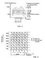
- Fig. 2 a division of the magnitude spectrum in bit layers shown parallel to Mit Bioschwelle.
- Spectral values represented by their bit patterns are spectral values as obtained, for example, by IntMDCT, which will be discussed later.
- the binary spectral values represented by their bit pattern may also reflect the results of any of the time domain / frequency domain conversion algorithms, e.g. As an FFT, and that represented as binary integers in principle of any size.
- Fig. 2 represented binary Spectral values have thus not yet been quantified using psychoacoustic considerations.
- the psychoacoustic listening threshold is plotted as a solid continuous line, which is denoted by 0 dB. Due to the progression of the masking threshold in the spectrum, parallel bit striations result - parallel to the masking threshold - and the fact that a bit belongs to a bit stratum reflects the psychoacoustic or psychooptical relevance of this bit. That's how it is Fig. 2 For example, it can be seen that the spectral value labeled "1" has bits occupying two bit layers above the listening threshold. In contrast, the even larger spectral value 5 is characterized in that it has higher-order bits occupying three bit layers above the listening threshold. The spectral values 2, 3 and 4, on the other hand, only comprise bits lying in a bit layer below the listening threshold.
- the listening threshold is referred to as the 0 dB line.
- the first scaling layer 111 of FIG Fig. 1b would therefore be in the in Fig. 2 shown only information about the spectral value 5 include.
- the second bit layer between 6 dB and 12 dB includes only information about bits of the first spectral value and the fifth spectral value, but no information about the other spectral values, since their MSB lie in lower bit layers.
- the third bit layer 113 in the in Fig. 2 The example shown includes the bits between the 0 dB line and the + 6 dB line in FIG Fig. 2 and now contains information about the sixth, the fifth and the first spectral line, but still no information about the other spectral values. If now the third scaling layer at the in Fig. 2 For example, as shown in FIG. 1, the precision scaling from the second scaling layer to the third scaling layer would be very strong, in that decoding only the first and second scaling layers - without the third scaling layer - would result in strong audible disturbances. On the other hand, consideration of the third scaling layer would lead to almost no audible interference.
- Fig. 3 shows a more detailed account of the situation in Fig. 2
- the Mit Bioschwelle no longer, as in Fig. 2 represented by their actual value, but in Fig. 3 with respect to its most significant bit.
- the accuracy scaling according to the invention is particularly interesting around the psychoacoustic masking threshold, ie for the bits of spectral values which have the same order as the MSB of the masking threshold associated with this spectral value. These bits are at the in Fig. 3 drawn diagram shown in bold-framed box.
- Fig. 3 In the vertical direction, the bit order is plotted, drawn from MSB via MSB-1, MSB-2, MSB-3, LSB + 2, LSB + 1 to LSB.
- MSB does not denote the MSB of a particular spectral value or a psychoacoustic masking threshold, but the absolute MSB, that is the maximum representable power of two in the binary system.
- Example shown thus includes the spectral value MSB bit 5, the MSB - 1 spectral value 4 bit, the MSB - 2 spectral value 3 bit, the MSB - 1 spectral value 2 bit, and the MSB spectral value 1 bit Therefore, the number of bits in the first scaling layer is 3 higher than the order of the bit in which the MSB of the masking threshold lies.
- the second scaling layer would then comprise the bits (MSB-1), (MSB-2), (MSB-3), (MSB-2) and (MSB-1) for the spectral values 5, 4, 3, 2 and 1.
- the third scaling layer would then use the bits (MSB-2), (MSB-3), (LSB + 2), (MSB-3) and (MSB-2) again for the spectral values 5, 4, 3, 2 and 1 include.
- the fourth scaling layer whose division into sub-scaling layers is preferred, would then make out the thick-edged bits Fig. 3 include (MSB - 3), (LSB + 2), (LSB + 1), (LSB + 2) and (MSB - 3) again for the spectral values 5, 4, 3, 2 and 1. Transmission of the first, second, third, and fourth scaling layers will result in psychoacoustic transparency, while if the fourth scaling layer were omitted, an accuracy penalty of 6 dB would be obtained.
- the fourth scaling layer in z. B. divided into five subscale layers, wherein in each subscale a Spektrlwertbit for a spectral value in the five spectral values comprising band will be provided.
- the course of the bit layers in the decoder can be traced, the monitoring threshold or the course of the just psychoacoustically significant bits, ie the MSBs of the listening threshold, to the decoder, for example, within the page information 110 of Fig. 1b transfer.
- the linewise representation and the bandwise representation are preferred.
- the masking threshold can be represented efficiently by the frequency response of a FIR filter with few coefficients or by polynomial interpolation due to its continuous course. In this case, a separate value of the listening threshold arises for each frequency value.
- the psychoacoustic masking effects underlying the listening threshold can be expressed in bands, the band division following the bark scale and preferably representing a refinement of the bark scale.
- This bandwise representation is also in known methods for hearing-adapted audio coding, such. As MPEG-2 AAC used. For the representation of the listening threshold, it is therefore sufficient to transmit one value per band.
- FIGS. 2 and 3 the definition of bit layers of equal psychoacoustic significance, for example in the IntMDCT spectrum.
- the bits as stated, beginning with the highest layer, are encoded and transmitted layer by layer.
- the transmitted signal Upon reaching the bit layer corresponding to the listening threshold (the in Fig. 3 bold-edged bits), the transmitted signal is psychoacoustically transparent.
- the transmission of further bit layers, ie bits below the in Fig. 3 illustrated thick rimmed boxes, increases the accuracy and thus the safety distance to the listening threshold.
- arithmetic coding is preferably used for redundancy reduction of the transmitted bits.
- the refinement of the accuracy scaling due to the partial scaling layers used according to the invention is particularly advantageous in the region above the masking threshold, at the masking threshold and below the masking threshold (based on the MSB of the masking threshold).
- accuracy scaling the bitwise transmission of the bits of the IntMDCT spectrum results in a 6 dB increase in accuracy. Note, however, that at least for noise-like signals, the Mit Selfschwelle is only about 6 dB below the signal, it can be seen that a scaling of the accuracy in 6-dB steps for efficient coding of the just audible signal components is often too coarse.
- the accuracy in each sublayer is increased for only one of m spectral lines. Since the psychoacoustic masking effects in the frequency domain occur bandwise and not line by line, increasing the accuracy of a spectral line gives the same accuracy gain per band as it does with the uniform increase in accuracy throughout the band.
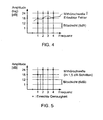
- Fig. 4 shows a case in which the listening threshold is shown line by line.
- the listening threshold is shown as a solid line.
- the MSB of the listening threshold is indicated by a "cross”.
- the decoding of all upstream in Fig. 4 Scaling layers not shown are already completed, so that the spectral values 1, 2, 3 and 4 are present with an accuracy represented by "0".
- the previously transmitted bit represented by "0" therefore represents the accuracy of the spectral line in the decoder.
- spectral value # 4 The next spectral value for the second subscale layer is spectral value # 4. Then, spectral value # 1 should follow for the third subscale layer, and finally spectral value # 3 for the fourth subcalation layer.
- the next bit to be coded will therefore be the frequency line with the largest difference between the accuracy of the previous one processed spectral value and the Mit tactileschwelle determined.
- this process can be reversed in the decoder, such that the decoder is able to find out, without additional page information, which spectral value is further refined by the next subcalculation layer to be decoded, as long as the decoder maintains the continuous course of the psychoacoustic masking threshold knows.
- Fig. 5 shows the case of the bandwise representation of the listening threshold.
- Out Fig. 5 results that the bits of the spectral values 2, 3, 4 are considered as the next to be processed subscale layers, since they are so far as compared to the listening threshold furthest from the same.
- the value of the spectral value 1 is already close to the monitoring threshold, so that the spectral value 1 does not necessarily have to be refined, but the spectral values 2, 3 and 4 must be used.
- each of the spectral values 2, 3, 4 could be taken into account in the next partial scaling layer.
- noise shaping can be achieved by taking into account the absolute value of the spectral values 2, 3 and 4, which have already been processed in the coder or processed in the decoder. If it turns out, for example, that the spectral value no. For example, if six more significant bits have been transmitted, indicating that the # 2 spectral value is very large, this means, relatively speaking, that this spectral value is already fairly well represented. On the other hand, it is found that the spectral value of No. 3 is a small spectral value in that only z. B.
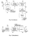
- Fig. 6 shows an overall block diagram of an encoder according to the invention.
- the time signal is fed to an input 600 in the encoder and z. B. implemented by means of an IntMDCT 602 in the frequency domain.
- a psychoacoustic model 84 is working, which in principle can have the same structure as the psychoacoustic model 84, which in Fig. 8 is shown.
- the masking threshold calculated by the psychoacoustic model 84 now does not become, as in FIG Fig. 8 , used to quantize, but to define 604 scaling layers.
- means 84 provides the MSB of the masking threshold, either per spectral value or per band, to a certain extent those in FIG Fig. 3 To determine determined "thick bordered" boxes.
- Means 604 then defines scaling layers relative to the order of MSBs of the masking threshold (the thick boxes in FIG Fig. 3 ).
- the scaling layer defining means 604 controls the means 102 for generating sub-scaling layers and for generating scaling layers, respectively, when both scaling layers and sub-scaling layers are to be employed.
- the device 102 would operate by first generating and supplying three complete scaling layers to arithmetic coding means 606 and then to the fourth scaling layer relating to the bits of the spectral values whose order is equal to the order of the MSBs of the masking threshold allocate a certain number of subscale layers.
- the scaling layers and the sub-scaling layers become one bit stream generated by a bit stream generator 608 to obtain a scaled / coded signal, which in principle corresponds to the in Fig. 1b can have shown structure.
- the scaled / coded signal is input to an input 700 of an in Fig. 7 fed decoder, wherein means 702 the in Fig. 1b
- An extracting / decoding device 704 then arithmetically codes the scaling layers and the sub-scaling layers sequentially, so that in a decoder-side, in Fig. 7 Not shown memory gradually build up the bit patterns of the individual spectral values.
- the decoder will eventually stop decoding further scaling layers or subscale layers. If all the coder-side generated scaling layers and sub-scaling layers have been transmitted and decoded in the bitstream, then lossless encoding / transmission / decoding has taken place and the decoder need not perform any interpretation of quantized values.
- the obtained spectral values after lossless or almost lossless encoding / transmission / decoding are fed to an inverse transformation device 706 which, for example, performs an inverse IntMDCT (IntMDCT -1 ) in order to obtain a decoded signal at an output 708.
- the decoder performs an interpretation of the previously available Spectral value bit pattern. If not all bit layers of the spectrum are transmitted, then only the most significant bits are present in the decoder for each spectral value.
- the decoder Knowing the listening threshold and the number of bit layers generated or to be generated in the decoder for the lossless case, the decoder now determines how many bit layers - and therefore how many bits - have not been transmitted for each individual spectral value. From this data, the decoder constructs a quantized spectral value. The simplest solution to this is to replace the untransmitted bits with zeros. In this case, the quantization process would always lead to a rounding off to smaller absolute values.
- the mean quantization error is kept as small as possible. This is achieved by using a so-called " Uniform Midrise Quantizer "is used, as described in NS Jayant, P. Noll:” Digital coding of waveforms ", Prentice-Hall, 1984 , is described. This quantizer leaves the quantization interval used in the quantization unchanged, but shifts the quantized value, ie the representative of the quantization interval and thus the interpretation of the transmitted bits by a certain value. A shift to the middle of the quantization interval is achieved, for example, if the bit pattern "1 0 0 0 " is used for the missing bits.
- the reconstruction bit pattern comprises at least a "1”, and preferably that the most significant bit of the reconstruction bit pattern is a "1".
- the IntMDCT spectrum provides an integer spectral representation of the audio signal. Parallel to this calculates the psychoacoustic model in Fig. 6 coders shown the Mit Bioschwelle.
- the monitoring threshold is, as has already been stated, efficiently encodable and transferable in the bitstream because of the continuous profile, for example by coefficients of an FIR filter or by polynomial interpolation.
- the number of bits that are not psychoacoustically significant ie the bits of the spectral values whose order is less than the order of the MSB of the masking threshold for this spectral value, results for each spectral line.
- Fig. 3 These are the bits below the thick rimmed boxes.
- Each magnitude value of the integer spectral values is represented bit by bit to then define bit layers of equal psychoacoustic significance, such as parallel to the layer of just-psychoacoustically significant bits, along the frequency domain 604, preferring low frequency preference in the more significant layers.
- the bits are ordered along the significance layers, starting with the most significant bit. The starting layer results either from the theoretical maximum values or from an efficiently coded spectral envelope, analogous to the coded listening threshold, or from a parallel shift of the listening threshold, such as. B. by 30 dB, which would correspond to five bits.
- the scalability range is extended not only to psychoacoustic transparency, as in MPEG-4 BSAC, but to lossless encoding / decoding. If the entire coded bit sequence and, if correspondingly displayed, also the associated signs of the spectral values are transmitted, the exemplary embodiment operates without loss. If only part of the coded bit sequence is transmitted, an irrelevance reduction already results. However, if the coded bit sequence is transmitted as far as the layer of just significant bits, then the method works in the just-transparent mode. If fewer bits are transmitted, the result is a reduction of the bit rate, which, however, is accompanied by a reduction of the audio / video quality.
- the audio signal (video signal) is displayed with an additional safety margin to the masking threshold and thus enables an almost lossless display with a high degree of robustness compared to postprocessing steps.
- the IntMDCT transformation algorithm which is described in " Audio Coding Based on Integer Transforms "111th AES Assembly, New York, 2001 , is described.
- the IntMDCT is particularly favorable because it has the attractive features of MDCT, such as: B. has a good spectral representation of the audio signal, a critical scan and a block overlap.
- Fig. 11 shows an overview diagram for the invention preferred device for processing discrete-time samples representing an audio signal to obtain integer values on which building the IntMDCT integer transformation algorithm works.
- the discrete-time samples are represented by the in. Fig. 11 fenfenert shown device and optionally converted into a spectral representation.
- the discrete-time samples fed into the device at an input 10 are windowed with a window w having a length corresponding to 2N discrete-time samples to obtain at an output 12 integer windowed samples suitable for use by a transformation, and in particular the means 14 for performing an integer DCT to be converted into a spectral representation.
- the integer DCT is designed to generate N output values from N input values, which in contrast to the MDCT function 408 of FIG Fig. 10a which generates only N spectral values from 2N windowed samples due to the MDCT equation.
- two time-discrete samples are first selected in a device 16, which together represent a vector of time-discrete samples.
- a discrete-time sample selected by means 16 is in the first quarter of the window.
- the other discrete-time sample is in the second quarter of the window as indicated by Fig. 13 is executed in more detail.
- the vector generated by the device 16 is now subjected to a rotating matrix of dimension 2 ⁇ 2, wherein this operation is not carried out directly, but by means of several so-called lifting matrices.
- a lifting matrix has the property that it has only one element, which depends on the window w and is not equal to "1" or "0".
- Each of the three lifting matrices standing to the right of the equals sign has the value "1" as main diagonal elements. Furthermore, in each lifting matrix, a secondary diagonal element is equal to 0, and a secondary diagonal element depends on the angle of rotation ⁇ .
- the vector is now multiplied by the third lifting matrix, ie the rightmost lifting matrix in the above equation, to obtain a first result vector.
- Fig. 11 represented by a device 18.
- the first result vector with any rounding function mapping the set of real numbers into the set of integers is rounded, as shown in FIG Fig. 11 is shown by a device 20.
- a rounded first result vector is obtained.
- the rounded first result vector is now fed into a means 22 for multiplying it by the middle, ie second, lifting matrix to obtain a second result vector which is in turn rounded in a means 24 to obtain a rounded second result vector.
- the rounded second result vector is now fed to a device 26 for multiplying it by the lifting equation matrix shown on the left in the above equation, to obtain a third result vector, which is finally rounded by means 28, and finally at the output 12, to obtain integer windowed samples which, if a spectral representation thereof is desired, now have to be processed by means 14 in order to obtain integer spectral values at a spectral output 30.
- the device 14 is implemented as an integer DCT or integer DCT.
- N x N matrix The coefficients of DCT-IV form an orthonormal N x N matrix.
- Each orthogonal N x N matrix can be decomposed into N (N-1) / 2 Givens rotations as described in the technical publication PP Vaidyanathan, "Multirate Systems and Filter Banks", Prentice Hall, Englewood Cliffs, 1993 , It should be noted that there are also further decompositions.
- DCT-IV includes non-symmetric basis functions, ie, a cosine quarter-wave, a cosine 3/4 wave, a cosine 5/4 wave, a cosine 7/4 wave, etc., the discrete cosine transform z.
- DCT-II Type II
- the 0th basic function has a DC component
- the first basic function is half a cosine wave
- the second basic function is a whole cosine wave, etc. Due to the fact that the DCT-II takes special account of the DC component, it is not used in the video coding in the audio coding, as in the audio coding in contrast to the video coding of the DC component is not relevant.
- An MDCT with a window length of 2N can be reduced to a type IV discrete cosine transform of length N. This is accomplished by explicitly performing the TDAC operation in the time domain and then applying the DCT-IV. For a 50% overlap, the left half of the window for a block t overlaps the right half of the previous block, ie, the block t-1. The overlapping part of two consecutive blocks t-1 and t is preprocessed in the time domain, ie before the transformation, as follows, i. H. between the input 10 and the output 12 of Fig.
- the values denoted by the tilde are the values at the output 12 of Fig. 11 while the x values denoted without tilde in the above equation are the values at the input 10 and behind the means 16 for selection, respectively.
- the running index k runs from 0 to N / 2-1, while w represents the window function.
- window functions w can be used as long as they satisfy this TDAC condition.
- the discrete-time samples x (0) to x (2N-1), which are "windowed" together by a window, are first passed through device 16 of FIG Fig. 11 the sample x (0) and the sample x (N-1), ie a sample from the first quarter of the window and a sample from the second quarter of the window, are selected to supply the vector at the output of the device 16 form.
- the crossing arrows represent schematically the lifting multiplications and subsequent roundings of the devices 18, 20 and 22, 24 and 26, 28, respectively, to obtain the integer windowed samples at the input of the DCT-IV blocks.
- a second vector of the samples x (N / 2-1) and x (N / 2) that is, one sample from the first quarter of the window and one sample from the second Quarter of the window, selected and in turn by the in Fig. 11 algorithm described.
- all other sample pairs from the first and second quarters of the window are processed.
- the same processing is performed for the third and fourth quarters of the first window.
- 2N windowed integer samples now in the same way as in FIG Fig. 12 is fed into a DCT-IV transformation.
- the integer windowed samples of the second and third quarters are fed to a DCT.
- the windowed integer samples of the first quarter of the window are processed into a previous DCT-IV along with the windowed integer samples of the fourth quarter of the previous window.
- the middle in Fig. 12 shown integer DCT-IV transformation 32 now provides N integer spectral values y (0) to y (N-1). These integer spectral values can now For example, it can be simply entropy coded without the need for intervening quantization because the fenestration and transform provides integer output values.
- a decoder In the right half of Fig. 12 a decoder is shown.
- the decoder consisting of inverse transformation and "inverse windowing" works inversely to the coder.
- an inverse DCT-IV can be used for the inverse transformation of a DCT-IV, as in Fig. 12 is shown.
- the output values of the decoder DCT-IV 34 will now be as shown in FIG Fig. 12 is inverse processed with the respective values of the preceding transformation and the subsequent transformation, respectively, to recover discrete-time audio samples x (0) to x (2N) from the integer windowed samples at the output of the device 34 and the preceding and following transformation, respectively. 1) to produce.
- the output side operation is done by inverse Givens rotation, ie, such that the blocks 26, 28, 22, 24 and 18, 20, respectively, are traversed in the opposite direction. This is illustrated in more detail with reference to the second lifting matrix of Equation 1. If (in the encoder) the second result vector is formed by multiplying the rounded first result vector by the second lifting matrix (means 22), the following expression results: x y ⁇ x . y + x ⁇ sin ⁇
- Equation 6 The values x, y on the right side of Equation 6 are integers. However, this does not apply to the value x sin ⁇ .
- the rounding function r must be introduced, as in the following equation x y ⁇ x . y + r x ⁇ sin ⁇ is shown. This operation executes the device 24.
- the inverse mapping (in the decoder) is defined as follows: x ' y ' ⁇ x ' . y ' - r x ' ⁇ sin ⁇
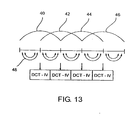
- Fig. 13 once again the decomposition of a conventional MDCT with overlapping windows 40 to 46 set forth.
- the windows 40 to 46 each overlap to 50%.
- the rotated values, ie, the windowed integer samples are fed into an N-to-N DCT such that always the second and third quarters of a window and the fourth and first quarters of a succeeding window together by means of a DCT-IV algorithm is converted into a spectral representation.
- Givens rotation is decomposed into lifting matrices which are executed sequentially, with a rounding step being introduced after each lifting matrix multiplication, such that the floating point numbers are rounded immediately after their formation, such that before every multiplication of a result vector with a lifting matrix, the result vector has only integers.
- the transformation shown provides integer output values instead of floating-point values. It provides a perfect reconstruction so that no error is introduced when forward and then backward transformations are performed.
- the transformation in accordance with a preferred embodiment of the present invention, is a replacement for the modified discrete cosine transform. Others too However, transformation techniques can be performed in integers as long as disassembly into rotations and decomposition of rotations into lifting steps is possible.
- the integer MDCT has the most favorable properties of the MDCT. It has an overlapping structure, which gives better frequency selectivity than non-overlapping block transforms. Due to the TDAC function already taken into account when windowing prior to transformation, a critical sample is maintained so that the total number of spectral values representing an audio signal is equal to the total number of input samples.
- the integer transformation provides a good spectral representation of the audio signal and still remains in the range of integers. When applied to tonal parts of an audio signal, this results in good energy concentration.
- an efficient lossless coding scheme can be built by simply using the in Fig. 11 shown windowing / transformation is cascaded with an entropy coder.
- stacked coding using escape values as it is used in MPEG AAC, is favorable. It is preferred to scale all values down by a certain power of two until they fit in a desired codebook, and then to additionally code the omitted least significant bits.
- the described alternative in terms of memory consumption for storing the code tables is more favorable.
- An almost lossless encoder could also be obtained by simply omitting certain of the least significant bits.
- entropy coding of the integer spectral values allows a high coding gain.
- the coding gain is low due to the flat spectrum of transient signals, ie due to a small number of spectral values equal to or near zero.
- TNS Temporal Noise Shaping
- the quantization after the prediction leads to an adaptation of the resulting quantization noise to the temporal structure of the audio signal and therefore prevents pre-echoes in psychoacoustic audio coders.
- the second alternative that is, with a closed-loop predictor, is more appropriate because closed loop prediction allows accurate reconstruction of the input signal.
- a center-side coding can be used lossless when a rounded rotation with an angle n / 4 is used.
- the rounded rotation has the advantage of conserving energy.
- the use of so-called joint stereo coding techniques can be turned on or off for each band, as is done in the standard MPEG AAC. Further rotation angles can also be taken into account in order to be able to reduce a redundancy between two channels more flexibly.
- the coding concept according to the invention or the decoding concept according to the invention can be implemented in hardware or in software.
- the implementation may be on a digital storage medium, in particular a floppy disk or CD with electronically readable control signals, which may interact with a programmable computer system such that the corresponding method is executed.
- the invention thus also consists in a computer program product with a program code stored on a machine-readable carrier for carrying out the coding method according to the invention or the decoding method according to the invention when the computer program product runs on a computer.
- the invention thus provides a computer program with a program code for carrying out the method for decoding or performing the method for coding when the computer program runs on a computer.
Landscapes
- Engineering & Computer Science (AREA)
- Physics & Mathematics (AREA)
- General Physics & Mathematics (AREA)
- Mathematical Physics (AREA)
- Health & Medical Sciences (AREA)
- Human Computer Interaction (AREA)
- Mathematical Analysis (AREA)
- Pure & Applied Mathematics (AREA)
- Computational Mathematics (AREA)
- Spectroscopy & Molecular Physics (AREA)
- Data Mining & Analysis (AREA)
- Multimedia (AREA)
- Acoustics & Sound (AREA)
- Mathematical Optimization (AREA)
- Theoretical Computer Science (AREA)
- Audiology, Speech & Language Pathology (AREA)
- Computational Linguistics (AREA)
- Signal Processing (AREA)
- Discrete Mathematics (AREA)
- Quality & Reliability (AREA)
- General Engineering & Computer Science (AREA)
- Software Systems (AREA)
- Databases & Information Systems (AREA)
- Algebra (AREA)
- Compression, Expansion, Code Conversion, And Decoders (AREA)
Applications Claiming Priority (3)
| Application Number | Priority Date | Filing Date | Title |
|---|---|---|---|
| DE10236694 | 2002-08-09 | ||
| DE10236694A DE10236694A1 (de) | 2002-08-09 | 2002-08-09 | Vorrichtung und Verfahren zum skalierbaren Codieren und Vorrichtung und Verfahren zum skalierbaren Decodieren |
| PCT/EP2003/008623 WO2004021710A2 (de) | 2002-08-09 | 2003-08-04 | Vorrichtung und verfahren zum skalierbaren codieren und vorrichtung und verfahren zum skalierbaren decodieren eines audiosignales |
Publications (2)
| Publication Number | Publication Date |
|---|---|
| EP1502255A2 EP1502255A2 (de) | 2005-02-02 |
| EP1502255B1 true EP1502255B1 (de) | 2014-11-19 |
Family
ID=30775133
Family Applications (1)
| Application Number | Title | Priority Date | Filing Date |
|---|---|---|---|
| EP03790855.5A Expired - Lifetime EP1502255B1 (de) | 2002-08-09 | 2003-08-04 | Vorrichtung und verfahren zum skalierbaren codieren und vorrichtung und verfahren zum skalierbaren decodieren eines audiosignales |
Country Status (8)
| Country | Link |
|---|---|
| US (1) | US7343287B2 (zh) |
| EP (1) | EP1502255B1 (zh) |
| JP (1) | JP4043476B2 (zh) |
| CN (1) | CN1332373C (zh) |
| AU (1) | AU2003250209A1 (zh) |
| DE (1) | DE10236694A1 (zh) |
| HK (1) | HK1072122A1 (zh) |
| WO (1) | WO2004021710A2 (zh) |
Families Citing this family (90)
| Publication number | Priority date | Publication date | Assignee | Title |
|---|---|---|---|---|
| US7461002B2 (en) * | 2001-04-13 | 2008-12-02 | Dolby Laboratories Licensing Corporation | Method for time aligning audio signals using characterizations based on auditory events |
| US7711123B2 (en) * | 2001-04-13 | 2010-05-04 | Dolby Laboratories Licensing Corporation | Segmenting audio signals into auditory events |
| US7610205B2 (en) * | 2002-02-12 | 2009-10-27 | Dolby Laboratories Licensing Corporation | High quality time-scaling and pitch-scaling of audio signals |
| DE10129240A1 (de) * | 2001-06-18 | 2003-01-02 | Fraunhofer Ges Forschung | Verfahren und Vorrichtung zum Verarbeiten von zeitdiskreten Audio-Abtastwerten |
| DE10234130B3 (de) * | 2002-07-26 | 2004-02-19 | Fraunhofer-Gesellschaft zur Förderung der angewandten Forschung e.V. | Vorrichtung und Verfahren zum Erzeugen einer komplexen Spektraldarstellung eines zeitdiskreten Signals |
| DE60330198D1 (de) | 2002-09-04 | 2009-12-31 | Microsoft Corp | Entropische Kodierung mittels Anpassung des Kodierungsmodus zwischen Niveau- und Lauflängenniveau-Modus |
| KR100917464B1 (ko) * | 2003-03-07 | 2009-09-14 | 삼성전자주식회사 | 대역 확장 기법을 이용한 디지털 데이터의 부호화 방법,그 장치, 복호화 방법 및 그 장치 |
| US7822150B2 (en) * | 2003-03-15 | 2010-10-26 | Alcatel-Lucent Usa Inc. | Spherical decoder for wireless communications |
| JP4486646B2 (ja) * | 2003-05-28 | 2010-06-23 | ドルビー・ラボラトリーズ・ライセンシング・コーポレーション | オーディオ信号の感知音量を計算し調整する方法、装置及びコンピュータプログラム |
| JP2007507790A (ja) * | 2003-09-29 | 2007-03-29 | エージェンシー フォー サイエンス,テクノロジー アンド リサーチ | 時間ドメインから周波数ドメインへ及びそれとは逆にデジタル信号を変換する方法 |
| KR100571824B1 (ko) * | 2003-11-26 | 2006-04-17 | 삼성전자주식회사 | 부가정보 삽입된 mpeg-4 오디오 bsac부호화/복호화 방법 및 장치 |
| KR100537517B1 (ko) * | 2004-01-13 | 2005-12-19 | 삼성전자주식회사 | 오디오 데이타 변환 방법 및 장치 |
| ATE390683T1 (de) | 2004-03-01 | 2008-04-15 | Dolby Lab Licensing Corp | Mehrkanalige audiocodierung |
| US7392195B2 (en) * | 2004-03-25 | 2008-06-24 | Dts, Inc. | Lossless multi-channel audio codec |
| KR100773539B1 (ko) * | 2004-07-14 | 2007-11-05 | 삼성전자주식회사 | 멀티채널 오디오 데이터 부호화/복호화 방법 및 장치 |
| CA2575379A1 (en) * | 2004-07-28 | 2006-02-02 | Matsushita Electric Industrial Co. Ltd. | Signal decoding apparatus |
| US7508947B2 (en) * | 2004-08-03 | 2009-03-24 | Dolby Laboratories Licensing Corporation | Method for combining audio signals using auditory scene analysis |
| DE102004041418A1 (de) * | 2004-08-26 | 2006-03-09 | Micronas Gmbh | Verfahren zur Codierung eines ersten und zweiten Datenwortes und Verfahren zur Decodierung eines codierten Datenwortes |
| US8090120B2 (en) * | 2004-10-26 | 2012-01-03 | Dolby Laboratories Licensing Corporation | Calculating and adjusting the perceived loudness and/or the perceived spectral balance of an audio signal |
| US8199933B2 (en) | 2004-10-26 | 2012-06-12 | Dolby Laboratories Licensing Corporation | Calculating and adjusting the perceived loudness and/or the perceived spectral balance of an audio signal |
| KR100685992B1 (ko) | 2004-11-10 | 2007-02-23 | 엘지전자 주식회사 | 디지털 방송 수신기에서 채널 전환시 정보 출력 방법 |
| EP1839297B1 (en) * | 2005-01-11 | 2018-11-14 | Koninklijke Philips N.V. | Scalable encoding/decoding of audio signals |
| TWI397903B (zh) * | 2005-04-13 | 2013-06-01 | Dolby Lab Licensing Corp | 編碼音訊之節約音量測量技術 |
| KR100818268B1 (ko) * | 2005-04-14 | 2008-04-02 | 삼성전자주식회사 | 오디오 데이터 부호화 및 복호화 장치와 방법 |
| BRPI0622303B1 (pt) * | 2005-04-18 | 2016-03-01 | Basf Se | copolímeros cp na forma de um polímero obtido por polimerização com radical de pelo menos três monômeros m diferentes monoetilenicamente insaturados |
| WO2006132857A2 (en) * | 2005-06-03 | 2006-12-14 | Dolby Laboratories Licensing Corporation | Apparatus and method for encoding audio signals with decoding instructions |
| WO2006134992A1 (ja) * | 2005-06-17 | 2006-12-21 | Matsushita Electric Industrial Co., Ltd. | ポストフィルタ、復号化装置及びポストフィルタ処理方法 |
| US7693709B2 (en) * | 2005-07-15 | 2010-04-06 | Microsoft Corporation | Reordering coefficients for waveform coding or decoding |
| US7684981B2 (en) * | 2005-07-15 | 2010-03-23 | Microsoft Corporation | Prediction of spectral coefficients in waveform coding and decoding |
| TWI396188B (zh) * | 2005-08-02 | 2013-05-11 | Dolby Lab Licensing Corp | 依聆聽事件之函數控制空間音訊編碼參數的技術 |
| US7565018B2 (en) * | 2005-08-12 | 2009-07-21 | Microsoft Corporation | Adaptive coding and decoding of wide-range coefficients |
| US7933337B2 (en) * | 2005-08-12 | 2011-04-26 | Microsoft Corporation | Prediction of transform coefficients for image compression |
| KR100738077B1 (ko) * | 2005-09-28 | 2007-07-12 | 삼성전자주식회사 | 계층적 오디오 부호화 및 복호화 장치와 방법 |
| CN101288309B (zh) * | 2005-10-12 | 2011-09-21 | 三星电子株式会社 | 处理/发送以及接收/处理比特流的方法和设备 |
| US8620644B2 (en) * | 2005-10-26 | 2013-12-31 | Qualcomm Incorporated | Encoder-assisted frame loss concealment techniques for audio coding |
| US7590523B2 (en) | 2006-03-20 | 2009-09-15 | Mindspeed Technologies, Inc. | Speech post-processing using MDCT coefficients |
| TWI517562B (zh) * | 2006-04-04 | 2016-01-11 | 杜比實驗室特許公司 | 用於將多聲道音訊信號之全面感知響度縮放一期望量的方法、裝置及電腦程式 |
| CN101410892B (zh) * | 2006-04-04 | 2012-08-08 | 杜比实验室特许公司 | 改进的离散余弦变换域中的音频信号响度测量及修改 |
| MY141426A (en) | 2006-04-27 | 2010-04-30 | Dolby Lab Licensing Corp | Audio gain control using specific-loudness-based auditory event detection |
| EP1855271A1 (en) * | 2006-05-12 | 2007-11-14 | Deutsche Thomson-Brandt Gmbh | Method and apparatus for re-encoding signals |
| DE102006022346B4 (de) * | 2006-05-12 | 2008-02-28 | Fraunhofer-Gesellschaft zur Förderung der angewandten Forschung e.V. | Informationssignalcodierung |
| EP1883067A1 (en) * | 2006-07-24 | 2008-01-30 | Deutsche Thomson-Brandt Gmbh | Method and apparatus for lossless encoding of a source signal, using a lossy encoded data stream and a lossless extension data stream |
| US8849433B2 (en) | 2006-10-20 | 2014-09-30 | Dolby Laboratories Licensing Corporation | Audio dynamics processing using a reset |
| US8521314B2 (en) * | 2006-11-01 | 2013-08-27 | Dolby Laboratories Licensing Corporation | Hierarchical control path with constraints for audio dynamics processing |
| DE102006051673A1 (de) * | 2006-11-02 | 2008-05-15 | Fraunhofer-Gesellschaft zur Förderung der angewandten Forschung e.V. | Vorrichtung und Verfahren zum Nachbearbeiten von Spektralwerten und Encodierer und Decodierer für Audiosignale |
| US8184710B2 (en) | 2007-02-21 | 2012-05-22 | Microsoft Corporation | Adaptive truncation of transform coefficient data in a transform-based digital media codec |
| JP4708446B2 (ja) * | 2007-03-02 | 2011-06-22 | パナソニック株式会社 | 符号化装置、復号装置およびそれらの方法 |
| US20100280830A1 (en) * | 2007-03-16 | 2010-11-04 | Nokia Corporation | Decoder |
| BRPI0813723B1 (pt) * | 2007-07-13 | 2020-02-04 | Dolby Laboratories Licensing Corp | método para controlar o nível de intensidade do som de eventos auditivos, memória legível por computador não transitória, sistema de computador e aparelho |
| CA2697604A1 (en) * | 2007-09-28 | 2009-04-02 | Voiceage Corporation | Method and device for efficient quantization of transform information in an embedded speech and audio codec |
| KR101238239B1 (ko) * | 2007-11-06 | 2013-03-04 | 노키아 코포레이션 | 인코더 |
| KR101597375B1 (ko) | 2007-12-21 | 2016-02-24 | 디티에스 엘엘씨 | 오디오 신호의 인지된 음량을 조절하기 위한 시스템 |
| US8386271B2 (en) * | 2008-03-25 | 2013-02-26 | Microsoft Corporation | Lossless and near lossless scalable audio codec |
| US8179974B2 (en) | 2008-05-02 | 2012-05-15 | Microsoft Corporation | Multi-level representation of reordered transform coefficients |
| KR101518532B1 (ko) | 2008-07-11 | 2015-05-07 | 프라운호퍼 게젤샤프트 쭈르 푀르데룽 데어 안겐반텐 포르슝 에. 베. | 오디오 인코더, 오디오 디코더, 오디오 신호, 오디오 스트림을 부호화 및 복호화하는 장치 및 컴퓨터 프로그램 |
| US8290782B2 (en) * | 2008-07-24 | 2012-10-16 | Dts, Inc. | Compression of audio scale-factors by two-dimensional transformation |
| US8406307B2 (en) | 2008-08-22 | 2013-03-26 | Microsoft Corporation | Entropy coding/decoding of hierarchically organized data |
| EP2237269B1 (en) * | 2009-04-01 | 2013-02-20 | Motorola Mobility LLC | Apparatus and method for processing an encoded audio data signal |
| FR2947944A1 (fr) * | 2009-07-07 | 2011-01-14 | France Telecom | Codage/decodage perfectionne de signaux audionumeriques |
| US8538042B2 (en) | 2009-08-11 | 2013-09-17 | Dts Llc | System for increasing perceived loudness of speakers |
| EP2306456A1 (en) * | 2009-09-04 | 2011-04-06 | Thomson Licensing | Method for decoding an audio signal that has a base layer and an enhancement layer |
| MX2012008075A (es) * | 2010-01-12 | 2013-12-16 | Fraunhofer Ges Forschung | Codificador de audio, decodificador de audio, metodo para codificar e informacion de audio, metodo para decodificar una informacion de audio y programa de computacion utilizando una modificacion de una representacion de un numero de un valor de contexto numerico previo. |
| US8374858B2 (en) * | 2010-03-09 | 2013-02-12 | Dts, Inc. | Scalable lossless audio codec and authoring tool |
| WO2012037515A1 (en) | 2010-09-17 | 2012-03-22 | Xiph. Org. | Methods and systems for adaptive time-frequency resolution in digital data coding |
| US9210442B2 (en) | 2011-01-12 | 2015-12-08 | Google Technology Holdings LLC | Efficient transform unit representation |
| US9380319B2 (en) | 2011-02-04 | 2016-06-28 | Google Technology Holdings LLC | Implicit transform unit representation |
| JP5625126B2 (ja) | 2011-02-14 | 2014-11-12 | フラウンホーファー−ゲゼルシャフト・ツール・フェルデルング・デル・アンゲヴァンテン・フォルシュング・アインゲトラーゲネル・フェライン | スペクトル領域ノイズ整形を使用する線形予測ベースコーディングスキーム |
| KR101525185B1 (ko) | 2011-02-14 | 2015-06-02 | 프라운호퍼 게젤샤프트 쭈르 푀르데룽 데어 안겐반텐 포르슝 에. 베. | 트랜지언트 검출 및 품질 결과를 사용하여 일부분의 오디오 신호를 코딩하기 위한 장치 및 방법 |
| BR112012029132B1 (pt) * | 2011-02-14 | 2021-10-05 | Fraunhofer - Gesellschaft Zur Förderung Der Angewandten Forschung E.V | Representação de sinal de informações utilizando transformada sobreposta |
| PL3239978T3 (pl) | 2011-02-14 | 2019-07-31 | Fraunhofer-Gesellschaft zur Förderung der angewandten Forschung e.V. | Kodowanie i dekodowanie pozycji impulsów ścieżek sygnału audio |
| CA2827249C (en) | 2011-02-14 | 2016-08-23 | Fraunhofer-Gesellschaft Zur Foerderung Der Angewandten Forschung E.V. | Apparatus and method for processing a decoded audio signal in a spectral domain |
| WO2012122299A1 (en) | 2011-03-07 | 2012-09-13 | Xiph. Org. | Bit allocation and partitioning in gain-shape vector quantization for audio coding |
| WO2012122297A1 (en) | 2011-03-07 | 2012-09-13 | Xiph. Org. | Methods and systems for avoiding partial collapse in multi-block audio coding |
| US8838442B2 (en) * | 2011-03-07 | 2014-09-16 | Xiph.org Foundation | Method and system for two-step spreading for tonal artifact avoidance in audio coding |
| WO2012137617A1 (ja) | 2011-04-05 | 2012-10-11 | 日本電信電話株式会社 | 符号化方法、復号方法、符号化装置、復号装置、プログラム、記録媒体 |
| US9312829B2 (en) | 2012-04-12 | 2016-04-12 | Dts Llc | System for adjusting loudness of audio signals in real time |
| US9225310B1 (en) * | 2012-11-08 | 2015-12-29 | iZotope, Inc. | Audio limiter system and method |
| US9967559B1 (en) | 2013-02-11 | 2018-05-08 | Google Llc | Motion vector dependent spatial transformation in video coding |
| US9544597B1 (en) * | 2013-02-11 | 2017-01-10 | Google Inc. | Hybrid transform in video encoding and decoding |
| US9674530B1 (en) | 2013-04-30 | 2017-06-06 | Google Inc. | Hybrid transforms in video coding |
| US9613634B2 (en) * | 2014-06-19 | 2017-04-04 | Yang Gao | Control of acoustic echo canceller adaptive filter for speech enhancement |
| US9565451B1 (en) | 2014-10-31 | 2017-02-07 | Google Inc. | Prediction dependent transform coding |
| US9742780B2 (en) * | 2015-02-06 | 2017-08-22 | Microsoft Technology Licensing, Llc | Audio based discovery and connection to a service controller |
| US9769499B2 (en) | 2015-08-11 | 2017-09-19 | Google Inc. | Super-transform video coding |
| US10277905B2 (en) | 2015-09-14 | 2019-04-30 | Google Llc | Transform selection for non-baseband signal coding |
| US9807423B1 (en) | 2015-11-24 | 2017-10-31 | Google Inc. | Hybrid transform scheme for video coding |
| CN110892478A (zh) * | 2017-04-28 | 2020-03-17 | Dts公司 | 音频编解码器窗口和变换实现 |
| US11272207B2 (en) | 2017-06-12 | 2022-03-08 | Futurewei Technologies, Inc. | Selection and signaling of motion vector (MV) precisions |
| WO2019091576A1 (en) * | 2017-11-10 | 2019-05-16 | Fraunhofer-Gesellschaft zur Förderung der angewandten Forschung e.V. | Audio encoders, audio decoders, methods and computer programs adapting an encoding and decoding of least significant bits |
| US11122297B2 (en) | 2019-05-03 | 2021-09-14 | Google Llc | Using border-aligned block functions for image compression |
Family Cites Families (8)
| Publication number | Priority date | Publication date | Assignee | Title |
|---|---|---|---|---|
| GB9512284D0 (en) * | 1995-06-16 | 1995-08-16 | Nokia Mobile Phones Ltd | Speech Synthesiser |
| GB9703441D0 (en) | 1997-02-19 | 1997-04-09 | British Tech Group | Progressive block-based coding for image compression |
| KR100261254B1 (ko) * | 1997-04-02 | 2000-07-01 | 윤종용 | 비트율 조절이 가능한 오디오 데이터 부호화/복호화방법 및 장치 |
| DE19742201C1 (de) | 1997-09-24 | 1999-02-04 | Fraunhofer Ges Forschung | Verfahren und Vorrichtung zum Codieren von Audiosignalen |
| KR100335609B1 (ko) * | 1997-11-20 | 2002-10-04 | 삼성전자 주식회사 | 비트율조절이가능한오디오부호화/복호화방법및장치 |
| DE19804564A1 (de) * | 1998-02-05 | 1999-08-12 | Fraunhofer Ges Forschung | Kommunikationsnetz, Verfahren zum Übertragen eines Signals, Netzverbindungseinheit und Verfahren zum Anpassen der Datenrate eines skalierten Datenstroms |
| US6446037B1 (en) * | 1999-08-09 | 2002-09-03 | Dolby Laboratories Licensing Corporation | Scalable coding method for high quality audio |
| DE10007171A1 (de) | 2000-02-17 | 2001-08-30 | Siemens Ag | Verfahren und Anordnung zur Codierung bzw. zur Codierung und Decodierung einer Zahlenfolge |
-
2002
- 2002-08-09 DE DE10236694A patent/DE10236694A1/de not_active Ceased
-
2003
- 2003-08-04 EP EP03790855.5A patent/EP1502255B1/de not_active Expired - Lifetime
- 2003-08-04 AU AU2003250209A patent/AU2003250209A1/en not_active Abandoned
- 2003-08-04 JP JP2004531856A patent/JP4043476B2/ja not_active Expired - Lifetime
- 2003-08-04 WO PCT/EP2003/008623 patent/WO2004021710A2/de active Application Filing
- 2003-08-04 CN CNB038190559A patent/CN1332373C/zh not_active Expired - Lifetime
- 2003-08-07 US US10/636,149 patent/US7343287B2/en active Active
-
2005
- 2005-06-08 HK HK05104838.3A patent/HK1072122A1/zh not_active IP Right Cessation
Also Published As
| Publication number | Publication date |
|---|---|
| AU2003250209A8 (en) | 2004-03-19 |
| WO2004021710A2 (de) | 2004-03-11 |
| CN1332373C (zh) | 2007-08-15 |
| US20040184537A1 (en) | 2004-09-23 |
| CN1675683A (zh) | 2005-09-28 |
| JP4043476B2 (ja) | 2008-02-06 |
| WO2004021710A3 (de) | 2004-04-22 |
| JP2005535940A (ja) | 2005-11-24 |
| US7343287B2 (en) | 2008-03-11 |
| DE10236694A1 (de) | 2004-02-26 |
| AU2003250209A1 (en) | 2004-03-19 |
| EP1502255A2 (de) | 2005-02-02 |
| HK1072122A1 (zh) | 2005-08-12 |
Similar Documents
| Publication | Publication Date | Title |
|---|---|---|
| EP1502255B1 (de) | Vorrichtung und verfahren zum skalierbaren codieren und vorrichtung und verfahren zum skalierbaren decodieren eines audiosignales | |
| EP1495464B1 (de) | Vorrichtung und verfahren zum codieren eines zeitdiskreten audiosignals und vorrichtung und verfahren zum decodieren von codierten audiodaten | |
| EP1647009B1 (de) | Vorrichtung und verfahren zum verarbeiten eines signals | |
| EP1025646B1 (de) | Verfahren und vorrichtung zum codieren von audiosignalen sowie verfahren und vorrichtungen zum decodieren eines bitstroms | |
| DE19811039B4 (de) | Verfahren und Vorrichtungen zum Codieren und Decodieren von Audiosignalen | |
| EP1609084B1 (de) | Vorrichtung und verfahren zum umsetzen in eine transformierte darstellung oder zum inversen umsetzen der transformierten darstellung | |
| EP1397799B1 (de) | Verfahren und vorrichtung zum verarbeiten von zeitdiskreten audio-abtastwerten | |
| EP1654674B1 (de) | Vorrichtung und verfahren zum verarbeiten von wenigstens zwei eingangswerten | |
| EP1687810B1 (de) | Vorrichtung und verfahren zum ermitteln einer quantisierer-schrittweite | |
| DE69731677T2 (de) | Verbessertes Kombinationsstereokodierverfahren mit zeitlicher Hüllkurvenformgebung | |
| DE60310716T2 (de) | System für die audiokodierung mit füllung von spektralen lücken | |
| EP3544003B1 (de) | Vorrichtung und verfahren zum ermitteln eines schätzwerts | |
| DE102006051673A1 (de) | Vorrichtung und Verfahren zum Nachbearbeiten von Spektralwerten und Encodierer und Decodierer für Audiosignale | |
| EP2054884A2 (de) | Vorrichtung zum kodieren und dekodieren | |
| EP1016319B1 (de) | Verfahren und vorrichtung zum codieren eines zeitdiskreten stereosignals | |
| DE60310449T2 (de) | Audiosignalkodierung | |
| DE102019204527B4 (de) | Kodierungs-/dekodierungsvorrichtungen und verfahren zur kodierung/dekodierung von vibrotaktilen signalen |
Legal Events
| Date | Code | Title | Description |
|---|---|---|---|
| PUAI | Public reference made under article 153(3) epc to a published international application that has entered the european phase |
Free format text: ORIGINAL CODE: 0009012 |
|
| 17P | Request for examination filed |
Effective date: 20041129 |
|
| AK | Designated contracting states |
Kind code of ref document: A2 Designated state(s): AT BE BG CH CY CZ DE DK EE ES FI FR GB GR HU IE IT LI LU MC NL PT RO SE SI SK TR |
|
| AX | Request for extension of the european patent |
Extension state: AL LT LV MK |
|
| REG | Reference to a national code |
Ref country code: HK Ref legal event code: DE Ref document number: 1072122 Country of ref document: HK |
|
| DAX | Request for extension of the european patent (deleted) | ||
| RBV | Designated contracting states (corrected) |
Designated state(s): AT CH DE FR GB LI NL |
|
| RIN1 | Information on inventor provided before grant (corrected) |
Inventor name: GEIGER, RALF Inventor name: SCHULLER, GERALD Inventor name: HERRE, JUERGEN Inventor name: BRANDENBURG, KARLHEINZ Inventor name: KOLLER, JUERGEN Inventor name: SPORER, THOMAS |
|
| 17Q | First examination report despatched |
Effective date: 20110404 |
|
| GRAP | Despatch of communication of intention to grant a patent |
Free format text: ORIGINAL CODE: EPIDOSNIGR1 |
|
| GRAJ | Information related to disapproval of communication of intention to grant by the applicant or resumption of examination proceedings by the epo deleted |
Free format text: ORIGINAL CODE: EPIDOSDIGR1 |
|
| GRAP | Despatch of communication of intention to grant a patent |
Free format text: ORIGINAL CODE: EPIDOSNIGR1 |
|
| INTG | Intention to grant announced |
Effective date: 20140506 |
|
| INTG | Intention to grant announced |
Effective date: 20140530 |
|
| INTG | Intention to grant announced |
Effective date: 20140604 |
|
| GRAS | Grant fee paid |
Free format text: ORIGINAL CODE: EPIDOSNIGR3 |
|
| GRAA | (expected) grant |
Free format text: ORIGINAL CODE: 0009210 |
|
| AK | Designated contracting states |
Kind code of ref document: B1 Designated state(s): AT CH DE FR GB LI NL |
|
| REG | Reference to a national code |
Ref country code: GB Ref legal event code: FG4D Free format text: NOT ENGLISH |
|
| REG | Reference to a national code |
Ref country code: CH Ref legal event code: EP |
|
| REG | Reference to a national code |
Ref country code: AT Ref legal event code: REF Ref document number: 697422 Country of ref document: AT Kind code of ref document: T Effective date: 20141215 |
|
| REG | Reference to a national code |
Ref country code: DE Ref legal event code: R096 Ref document number: 50315165 Country of ref document: DE Effective date: 20150108 |
|
| REG | Reference to a national code |
Ref country code: NL Ref legal event code: VDEP Effective date: 20141119 |
|
| PG25 | Lapsed in a contracting state [announced via postgrant information from national office to epo] |
Ref country code: NL Free format text: LAPSE BECAUSE OF FAILURE TO SUBMIT A TRANSLATION OF THE DESCRIPTION OR TO PAY THE FEE WITHIN THE PRESCRIBED TIME-LIMIT Effective date: 20141119 |
|
| REG | Reference to a national code |
Ref country code: DE Ref legal event code: R097 Ref document number: 50315165 Country of ref document: DE |
|
| PLBE | No opposition filed within time limit |
Free format text: ORIGINAL CODE: 0009261 |
|
| STAA | Information on the status of an ep patent application or granted ep patent |
Free format text: STATUS: NO OPPOSITION FILED WITHIN TIME LIMIT |
|
| 26N | No opposition filed |
Effective date: 20150820 |
|
| REG | Reference to a national code |
Ref country code: CH Ref legal event code: PL |
|
| PG25 | Lapsed in a contracting state [announced via postgrant information from national office to epo] |
Ref country code: CH Free format text: LAPSE BECAUSE OF NON-PAYMENT OF DUE FEES Effective date: 20150831 Ref country code: LI Free format text: LAPSE BECAUSE OF NON-PAYMENT OF DUE FEES Effective date: 20150831 |
|
| REG | Reference to a national code |
Ref country code: HK Ref legal event code: GR Ref document number: 1072122 Country of ref document: HK |
|
| REG | Reference to a national code |
Ref country code: FR Ref legal event code: PLFP Year of fee payment: 14 |
|
| REG | Reference to a national code |
Ref country code: AT Ref legal event code: MM01 Ref document number: 697422 Country of ref document: AT Kind code of ref document: T Effective date: 20150804 |
|
| PG25 | Lapsed in a contracting state [announced via postgrant information from national office to epo] |
Ref country code: AT Free format text: LAPSE BECAUSE OF NON-PAYMENT OF DUE FEES Effective date: 20150804 |
|
| REG | Reference to a national code |
Ref country code: FR Ref legal event code: PLFP Year of fee payment: 15 |
|
| REG | Reference to a national code |
Ref country code: FR Ref legal event code: PLFP Year of fee payment: 16 |
|
| PGFP | Annual fee paid to national office [announced via postgrant information from national office to epo] |
Ref country code: GB Payment date: 20220824 Year of fee payment: 20 Ref country code: DE Payment date: 20220822 Year of fee payment: 20 |
|
| PGFP | Annual fee paid to national office [announced via postgrant information from national office to epo] |
Ref country code: FR Payment date: 20220822 Year of fee payment: 20 |
|
| P01 | Opt-out of the competence of the unified patent court (upc) registered |
Effective date: 20230512 |
|
| REG | Reference to a national code |
Ref country code: DE Ref legal event code: R071 Ref document number: 50315165 Country of ref document: DE |
|
| REG | Reference to a national code |
Ref country code: GB Ref legal event code: PE20 Expiry date: 20230803 |
|
| PG25 | Lapsed in a contracting state [announced via postgrant information from national office to epo] |
Ref country code: GB Free format text: LAPSE BECAUSE OF EXPIRATION OF PROTECTION Effective date: 20230803 |