EP1502063B1 - Freeze-drying device - Google Patents
Freeze-drying device Download PDFInfo
- Publication number
- EP1502063B1 EP1502063B1 EP03722477A EP03722477A EP1502063B1 EP 1502063 B1 EP1502063 B1 EP 1502063B1 EP 03722477 A EP03722477 A EP 03722477A EP 03722477 A EP03722477 A EP 03722477A EP 1502063 B1 EP1502063 B1 EP 1502063B1
- Authority
- EP
- European Patent Office
- Prior art keywords
- heating
- temperature
- plates
- chamber
- cooling
- Prior art date
- Legal status (The legal status is an assumption and is not a legal conclusion. Google has not performed a legal analysis and makes no representation as to the accuracy of the status listed.)
- Expired - Lifetime
Links
- 238000004108 freeze drying Methods 0.000 title description 20
- 238000001816 cooling Methods 0.000 claims abstract description 83
- 238000010438 heat treatment Methods 0.000 claims abstract description 77
- 238000001035 drying Methods 0.000 claims abstract description 65
- 239000000463 material Substances 0.000 claims abstract description 23
- 238000000034 method Methods 0.000 claims abstract description 10
- 239000002904 solvent Substances 0.000 claims abstract description 8
- 238000007710 freezing Methods 0.000 claims description 10
- 230000008014 freezing Effects 0.000 claims description 10
- 125000006850 spacer group Chemical group 0.000 claims description 8
- 230000005855 radiation Effects 0.000 claims description 7
- 230000001954 sterilising effect Effects 0.000 claims description 6
- 230000001105 regulatory effect Effects 0.000 claims description 4
- 229910001220 stainless steel Inorganic materials 0.000 claims description 3
- 239000010935 stainless steel Substances 0.000 claims description 3
- 230000006978 adaptation Effects 0.000 claims description 2
- 230000000750 progressive effect Effects 0.000 claims 1
- 238000012546 transfer Methods 0.000 abstract description 10
- 238000010276 construction Methods 0.000 description 5
- 230000001419 dependent effect Effects 0.000 description 5
- 239000007789 gas Substances 0.000 description 5
- 239000000523 sample Substances 0.000 description 5
- 238000000859 sublimation Methods 0.000 description 5
- 230000008022 sublimation Effects 0.000 description 5
- IJGRMHOSHXDMSA-UHFFFAOYSA-N Atomic nitrogen Chemical compound N#N IJGRMHOSHXDMSA-UHFFFAOYSA-N 0.000 description 4
- 238000013459 approach Methods 0.000 description 4
- 238000004364 calculation method Methods 0.000 description 4
- 238000010586 diagram Methods 0.000 description 4
- 230000008030 elimination Effects 0.000 description 4
- 238000003379 elimination reaction Methods 0.000 description 4
- 238000005259 measurement Methods 0.000 description 3
- 238000004659 sterilization and disinfection Methods 0.000 description 3
- 239000004020 conductor Substances 0.000 description 2
- 238000009413 insulation Methods 0.000 description 2
- 238000009533 lab test Methods 0.000 description 2
- 238000002156 mixing Methods 0.000 description 2
- 229910052757 nitrogen Inorganic materials 0.000 description 2
- 206010013786 Dry skin Diseases 0.000 description 1
- 238000009529 body temperature measurement Methods 0.000 description 1
- 239000003990 capacitor Substances 0.000 description 1
- 238000004140 cleaning Methods 0.000 description 1
- 238000004590 computer program Methods 0.000 description 1
- 239000002826 coolant Substances 0.000 description 1
- 238000013461 design Methods 0.000 description 1
- 208000037265 diseases, disorders, signs and symptoms Diseases 0.000 description 1
- 230000000694 effects Effects 0.000 description 1
- 238000011156 evaluation Methods 0.000 description 1
- 238000002474 experimental method Methods 0.000 description 1
- 239000013529 heat transfer fluid Substances 0.000 description 1
- 239000012774 insulation material Substances 0.000 description 1
- 210000000056 organ Anatomy 0.000 description 1
- 230000003014 reinforcing effect Effects 0.000 description 1
- 229920002545 silicone oil Polymers 0.000 description 1
- 238000004088 simulation Methods 0.000 description 1
- 238000005496 tempering Methods 0.000 description 1
Images


Classifications
-
- F—MECHANICAL ENGINEERING; LIGHTING; HEATING; WEAPONS; BLASTING
- F26—DRYING
- F26B—DRYING SOLID MATERIALS OR OBJECTS BY REMOVING LIQUID THEREFROM
- F26B5/00—Drying solid materials or objects by processes not involving the application of heat
- F26B5/04—Drying solid materials or objects by processes not involving the application of heat by evaporation or sublimation of moisture under reduced pressure, e.g. in a vacuum
- F26B5/06—Drying solid materials or objects by processes not involving the application of heat by evaporation or sublimation of moisture under reduced pressure, e.g. in a vacuum the process involving freezing
Definitions
- the invention relates to a freeze-drying chamber with coolable / heatable shelves for a variety of istgefiillten containers or assignable with product layers cool / heatable control panels with special facilities that eliminate the drying progress dependent harmful temperature influences the chamber wall surfaces.
- Special versions allow the avoidance of high energy loss through a special chamber wall construction with simultaneous mass reduction of the tempered components
- Driving potential for drying are temperature differences between product-filled containers or product layers and their environment, which provides the potential necessary for the progress of freeze-drying. This potential is greater in the edge region of the control panels than in the middle of the control panel, because direct heat exchange by radiation and convection takes place between containers at the edge and the chamber wall.
- the natural convection of the gas in the free gap between wall and temperature-controlled control panels acts particularly strongly as a heat carrier for the convection current exposed container. These additional heat flows decrease towards the center of the plate and thus cause the inhomogeneous freezing and drying process of the containers or product layers distributed over the plate.
- Freeze dryers are made according to the prior art either entirely without tempering the chamber walls or with heating /deinäntelt which are applied directly to the supporting structure.
- These heating / cooling jackets have the purpose of the chamber to cool down from the sterilization temperature to the temperature suitable for loading because of the short to ground with the heavy supporting structure of the chamber. Thereafter, the coolant is usually emptied from these heating / cooling surfaces to reduce mass.
- the cooling of the chamber wall to a temperature which eliminates the driving potential responsible for the disturbance is not possible with these constructions.
- the invention relates to a drying apparatus for removing solvent from moist material, comprising at least one drying chamber with at least one adjusting plate for receiving wet-filled containers or layers of moist material, wherein the drying chamber is connected to a condenser via a vapor channel in which the sublimated solvent is separable, wherein the control panels are connected to a temperature-controlled heating / cooling circuit, the chamber having heating / cooling plates, which are connected to a second heat transfer circuit and wherein the Heating / cooling plates are carried out largely thermally decoupled from the chamber wall, characterized in that the heating / cooling plates are suspended parallel to the edges of the adjusting plates at a distance from the adjusting plates in the drying chamber, so that the hanging heating / cooling plates a nearly closed Form radiation cage around the stack of piles.
- the elimination of the non-uniformity is achieved by controlled heating / cooling plates, which surround the control panels like a radiation cage, which are adjusted so that there is no driving temperature gradient between wall and container.
- the resulting homogeneity of the freezing and drying process of all containers can improve the uniformity of the product quality and significantly increase the drying capacity.
- control panels can be provided with a piping system.
- the pipe system is traversed by a stream of temperature-controlled heat transfer medium, which is supplied from a heating / cooling system.
- a preferred drying apparatus is characterized in that the heating / cooling plates are spaced from the chamber wall.
- the outer chamber wall is pressure-resistant, so that the surface forces are absorbed without deformation during evacuation of the chamber.
- drying apparatus wherein the outer chamber wall has thermal insulation to minimize energy loss of the system.
- thermoforming apparatus in which the heating / cooling plates are vacuum-tightly connected to the chamber wall, so that effectively results in a 2-chamber system
- the heating / cooling surfaces are mechanically connected in particular via spacers with the inside of the chamber wall and form with this an evacuated planar gap.
- vacuum connections are provided in the chamber wall.
- Preference is furthermore a drying apparatus, characterized in that the gap is adjustable by a vacuum system to the pressure level of the drying chamber for the purpose of pressure equalization.
- the spacers are preferably made of poorly heat-conducting material, in particular stainless steel.
- a particular embodiment of the drying apparatus is characterized in that elastic connecting plates between the side heating / cooling plates and the chamber wall are designed so flexible that the temperature-induced changes in length of the heating / cooling surfaces are compensated without material damage.
- the drying chamber is already evacuated during the freezing process in order to reduce convection influences.
- the chamber wall has a special design on an external heat insulation.
- the CIP / SIP devices are mounted so that all surfaces can be cleaned.
- a drying apparatus characterized in that the temperature control systems for the heating / cooling plates are sensor-controlled to the appropriate temperature adjustable.
- the temperature control systems for the heating / cooling plates are predictively controlled by a computer program controlled to the appropriate temperature.
- the temperature control systems for the heating / cooling plates are controlled by a hybrid system of sensor and computer and set to the appropriate temperature.
- the inventive arrangement of the heating / cooling plates equal mass ratios between heating / cooling plates and control panels are made and thus allows approximately the same temperature / time profiles for walls and panels / container.
- the regulation / control of the heating / cooling plate temperature can be carried out according to the following strategies:
- Sensor-controlled control During the freezing phase, the control panels and heating / cooling plates are controlled following the same temperature program. After the start of the drying program, the heating / cooling plate temperature and the plate temperature follow different programs. The platen temperature is determined by the given Lyozyklus and it is traversed and regulated in the Lyozyklus specified temperature / Zeitprogamm. The temperature of the heating / cooling plates is set in the first drying section on the sublimation of the frozen product, which adjusts chamber pressure-dependent and solvent-dependent. As a first approximation, this temperature can be calculated on the basis of the material values. Measurements of the sublimation temperature in the laboratory experiment can be used to correct this calculated temperature. It is also possible to use the pressure rise method for the direct determination of the sublimation temperature, as described, for example, by GW Oetjen in "Gefriertrocknen", VCH Verlag, 1997.
- the temperature of the heating / cooling plates must be changed when the second drying section starts.
- the beginning of the second drying section can be detected by measuring the system pressure in the gas stream from the freezing chamber with different pressure measuring probes, eg: an absolute pressure gauge and a conductivity probe (eg Pirani probe) set to nitrogen. If the solvent vapor flow approaches 0 at the end of the first drying section, both measured values approach the same value, since the nitrogen content in the gas flow increases steadily and thus the measured value of the Pirani probe approaches more and more the absolute pressure measured value.
- the temperature of the heating / cooling plates can now be slowly raised to the plate temperature and be tracked in the further course of drying the platen temperature. For example, the degree of approach to the platen temperature is determined as a function of the pressure difference between the two pressure readings.
- Predictive control of the heating / cooling plates If, in the laboratory test, drying characteristics were recorded on the product to be dried under defined conditions and a drying program was used to determine all freeze drying properties / parameters of the product, the drying process can be determined with knowledge of the freeze drying properties of the freeze dryer of the product and the values of the product temperature determined by the calculation program are used as the reference variable for the heating / cooling plate temperatures. This method is in Fig. 3b shown.
- Hybrid method From the measurements in the freeze dryer (absolute pressure, pressure according to conductivity probe) and simulation calculations, the product temperatures are determined and used as a reference variable for the heating / cooling plate temperature.
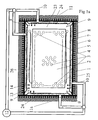
- a conventional system of freeze-drying chamber 1 and condenser chamber 22 is shown in which packages of product-filled containers are frozen and freeze-dried.
- Container 3 are indicated on the shelf 2 in the edge and middle area standing.
- the chamber 1 has two separately openable doors 11, 11a, which are sealed.
- the freeze-drying chamber 1 has a bivalve structure.
- the heavy chamber wall construction 6 with reinforcing ribs 7 has the task of offering a vacuum-tight, torsionally stiff housing, which withstands atmospheric pressure during evacuation of the freeze-drying chamber 1, for the second, inner chamber 23 integrated therein.
- the chamber 1 is equipped with thermal insulation material 8 on its outside against heat exchange with the environment.
- the inner freeze-drying chamber 23 is formed from the heating / cooling plates 4, which are held by means of spacers 5 at a distance from the chamber wall 6, pressure-tight connected via flexible sheets 9 with the chamber wall 6, so that the gap 24 between heating / cooling plates and supporting wall 6 of the chamber 1 can be evacuated.
- the evacuation takes place via pipelines 10, 12, which are connected to the main vacuum pump 21 via valves 20.
- the evacuation of the gap 24 serves two purposes: First, the pressure equalization between freeze-drying chamber 23 and the space 24 between heating / cooling plates 4 and chamber wall 6, so that pressure forces on the heating / cooling plates 4 are avoided. Second, it serves to lower the heat exchanger by the pressure-dependent lowering of the effective heat conduction of the intermediate space 24.
- the same pressure as in the freeze-drying chamber 23 p ⁇ 0.1 mbar
- the gap 24 as the evacuated Gap of a Dewar flask acts.
- the spacers 5 between the heating / cooling plates 4 and the chamber wall 6 are made of a poorly heat-conductive material (eg stainless steel), and the number of spacers 5 is minimized to the necessary extent, so that the heat transfer is minimized by heat conduction through the spacers 5 ,
- the connecting plates 9 are structurally designed so that the temperature-dependent change in length of the heating / cooling plates 4 can be absorbed by the sheets without risk to the mechanical strength of the connection to the chamber wall 6. In this way, a smooth-surface freeze-drying chamber 23, which can be easily cleaned.
- the heating / cooling plates 4 are supplied via a separately controllable temperature control (not shown) with heat transfer fluid (silicone oil), which is discharged via the line 13 and line 14.
- the temperature control system uses the same heat transfer medium as the control panels and can be supplied from the same reservoir.
- the temperature control system for the heating / cooling plates 4 must always be operated with a temperature adjusted to the vial temperature, while the heat transfer medium for the control plates 2 follows another temperature program following the Lyo cycle.
- the temperature program for the heating / cooling plates 4 depends on the temperature of the container. This method is already described in general above.
- FIG. 2 another embodiment of the freeze dryer with respect to the attachment of heating / cooling plates 4 'is shown.
- the tempered plates 4 ' hang freely in the chamber 23.
- the heating / cooling plates 4' are suspended parallel to the edges of the panels 2 at a distance, so that space for all the panels 2 associated organs eg tubes 25, 26 for the Heat transfer medium, shelf holder (not shown), is maintained.
- Known CIP / SIP devices can also be provided in the chamber interior.
- the heating / cooling plates 4 'are in turn fed by a separate heat transfer circuit via inlet 13 and return 14 with the heat transfer medium.
- the crowd the heating / cooling plates corresponds in both cases (according to Example 1 and 2) of the mass of the adjusting plates 2, so that the heating / cooling dynamics of the plates 2 and 4 or 4 'are matched and no temperature shifts caused by mass inequality.
Abstract
Description
Die Erfindung bezieht sich auf eine Gefriertrocknungskammer mit kühl-/heizbaren Stellplatten für eine Vielzahl von produktgefiillten Behältern oder mit Produktschichten belegbaren kühl-/heizbaren Stellplatten mit besonderen Einrichtungen, welche die vom Trocknungsfortschritt abhängigen schädlichen Temperatureinflüsse der Kammerwandflächen beseitigen. Spezielle Ausführungen ermöglichen die Vermeidung von hohem Energieverlust durch einen speziellen Kammerwandaufbau bei gleichzeitiger Massereduzierung der temperierten BauteileThe invention relates to a freeze-drying chamber with coolable / heatable shelves for a variety of produktgefiillten containers or assignable with product layers cool / heatable control panels with special facilities that eliminate the drying progress dependent harmful temperature influences the chamber wall surfaces. Special versions allow the avoidance of high energy loss through a special chamber wall construction with simultaneous mass reduction of the tempered components
Bei der Trocknung in bekannten Gefriertrockenkammern mit einer Vielzahl von Stellplatten für produktgefüllte Container oder ebene Produktschichten haben die Container oder Produktschichten im Randbereich der Stellplatten durch Strahlungswärmeaustausch und natürliche Konvektion im Spalt zwischen Wand und Stellplattenstapel einen intensiveren Energieaustausch als die in Plattenmitte positionierten Container/Produktschichten. Durch diese Inhomogenität der Energieverteilung kommt es zu unterschiedlicher Einfrier- und Trocknungskinetik beim Vergleich zwischen randseitigen und in der Mitte angeordneten Containern bzw. Produktschichten.When drying in known freeze-drying chambers with a variety of shelves for product-filled containers or even product layers, the containers or product layers in the edge region of the panels by radiation heat exchange and natural convection in the gap between the wall and stack of stacks have a more intensive energy exchange than the container / product layers positioned in the middle of the plate. This inhomogeneity of the energy distribution leads to different freezing and drying kinetics when comparing containers arranged at the edge and in the middle, or product layers.
Die Vermeidung der Inhomogenität wird erreicht durch die Beseitigung des für die Ungleichmäßigkeiten verantwortlichen treibenden Potenzials. Treibendes Potenzial für die Trocknung sind Temperaturunterschiede zwischen produktgefüllten Containern bzw. Produktschichten und ihrer Umgebung, welche das für den Fortgang der Gefriertrocknung notwendige Potenzial liefert. Im Randbereich der Stellplatten ist dieses Potenzial größer als im mittleren Bereich der Stellplatte, weil direkter Wärmeaustausch durch Strahlung und Konvektion zwischen Containern am Rand und der Kammerwand stattfindet. Während des Einfriervorgangs nach dem Stand der Technik (bei Normal- bzw. leicht abgesenktem Druck) wirkt die natürliche Konvektion des Gases im freien Spalt zwischen Wand und temperaturgeregelten Stellplatten besonders stark als Wärmeträger für die dem Konvektionsstrom exponierten Container. Diese zusätzlichen Wärmeströme nehmen zur Plattenmitte hin ab und verursachen dadurch den inhomogenen Einfrier- und Trocknungsverlauf der über die Platte verteilten Container bzw. Produktschichten.The avoidance of inhomogeneity is achieved by eliminating the driving potential responsible for the irregularities. Driving potential for drying are temperature differences between product-filled containers or product layers and their environment, which provides the potential necessary for the progress of freeze-drying. This potential is greater in the edge region of the control panels than in the middle of the control panel, because direct heat exchange by radiation and convection takes place between containers at the edge and the chamber wall. During the freezing process according to the prior art (at normal or slightly reduced pressure), the natural convection of the gas in the free gap between wall and temperature-controlled control panels acts particularly strongly as a heat carrier for the convection current exposed container. These additional heat flows decrease towards the center of the plate and thus cause the inhomogeneous freezing and drying process of the containers or product layers distributed over the plate.
Gefriertrockner werden nach dem Stand der Technik entweder ganz ohne Temperiervorrichtung für die Kammerwände oder aber mit Heiz-/Kühlinänteln hergestellt, die direkt auf die tragende Konstruktion aufgebracht sind. Diese Heiz-/Kühlmäntel haben wegen des Masseschlusses mit der schweren Tragkonstruktion der Kammer den Zweck, die Kammer von der Sterilisierungstemperatur auf die zum Beladen geeignete Temperatur herunterzukühlen. Danach wird in der Regel die Kühlflüssigkeit aus diesen Heiz-/ Kühlflächen entleert, um Masse zu reduzieren. Die Abkühlung der Kammerwand auf eine Temperatur, die das für die Störung verantwortliche treibende Potenzial beseitigt, ist mit diesen Konstruktionen nicht möglich.Freeze dryers are made according to the prior art either entirely without tempering the chamber walls or with heating / Kühlinäntelt which are applied directly to the supporting structure. These heating / cooling jackets have the purpose of the chamber to cool down from the sterilization temperature to the temperature suitable for loading because of the short to ground with the heavy supporting structure of the chamber. Thereafter, the coolant is usually emptied from these heating / cooling surfaces to reduce mass. The cooling of the chamber wall to a temperature which eliminates the driving potential responsible for the disturbance is not possible with these constructions.
In der Schrift
- 1. Die zusätzlichen Kühlflächen sind in die mechanische Tragkonstruktion des Trockners integriert, die für eine Evakuierung hinreichend armiert sein muss. Dies bewirkt den Nachteil, im Betrieb des Trockners große Massen heizen/- kühlen zu müssen. Daher reagiert der Trockner notwendigerweise thermisch träge.
- 2. Die Regelung entsprechend
US-A-5 398 426 JP-A-02169984
- 1. The additional cooling surfaces are integrated into the mechanical support structure of the dryer, which must be adequately armored for evacuation. This has the disadvantage of having to heat / cool large masses during operation of the dryer. Therefore, the dryer necessarily reacts thermally inert.
- 2. The regulation accordingly
US-A-5,398,426 JP-A-02169984
Der Erfindung liegen daher folgende Aufgaben zugrunde:
- Beseitigung der Ungleichmäßigkeit zwischen Rand- und Mittenbereich der Stellplatten die bei dem Einfrieren und Trocknen von produktgefüllten Behältern zu ungleichen Temperatur-und Trocknungsverläufen der Behälter führt.
- Elimination of non-uniformity between the edge and center areas of the panels, which leads to uneven temperature and drying characteristics of the containers during the freezing and drying of product-filled containers.
Die Beseitigung der Ungleichmäßigkeit wird erreicht durch geregelte Heiz-/Kühlplatten, die die Stellplatten wie einen Strahlungskäfig umgeben, die so eingestellt werden, dass kein treibendes Temperaturgefälle zwischen Wand und Behälter herrscht. Durch die dadurch erreichte Homogenität des Einfrier- und Trocknungsprozesses aller Behälter kann die Gleichmäßigkeit der Produktqualität und die Trocknungskapazität erheblich erhöht werden.The elimination of the non-uniformity is achieved by controlled heating / cooling plates, which surround the control panels like a radiation cage, which are adjusted so that there is no driving temperature gradient between wall and container. The resulting homogeneity of the freezing and drying process of all containers, the uniformity of the product quality and the drying capacity can be significantly increased.
Gegenstand der Erfindung ist ein Trocknungsapparat zur Entfernung von Lösungsmittel aus Feuchtgut, bestehend wenigstens aus einer Trockenkammer mit wenigstens einer Stellplatte zur Aufnahme von mit Feuchtgut gefüllten Behältern oder ebenen Schichten aus Feuchtgut, wobei die Trockenkammer mit einem Kondensator über einen Brüdenkanal verbunden ist, in dem das sublimierte Lösungsmittel abscheidbar ist, wobei die Stellplatten mit einem temperaturgeregelten Heiz-/Kühlkreislauf verbunden sind, wobei die Kammer Heiz-/Kühlplatten aufweist, die mit einem zweiten Wärmeträgerkreislauf verbunden sind und wobei die Heiz-/Kühlkplatten von der Kammerwand weitgehend thermisch entkoppelt ausgeführt sind, dadurch gekennzeichnet, dass die Heiz-/Kühlplatten parallel zu den Kanten der Stellplatten in Abstand zu den Stellplatten in der Trockenkammer aufgehängt sind, so dass die hängenden Heiz-/Kühlplatten einen nahezu geschlossenen Strahlungskäfig um den Stellplattenstapel bilden.The invention relates to a drying apparatus for removing solvent from moist material, comprising at least one drying chamber with at least one adjusting plate for receiving wet-filled containers or layers of moist material, wherein the drying chamber is connected to a condenser via a vapor channel in which the sublimated solvent is separable, wherein the control panels are connected to a temperature-controlled heating / cooling circuit, the chamber having heating / cooling plates, which are connected to a second heat transfer circuit and wherein the Heating / cooling plates are carried out largely thermally decoupled from the chamber wall, characterized in that the heating / cooling plates are suspended parallel to the edges of the adjusting plates at a distance from the adjusting plates in the drying chamber, so that the hanging heating / cooling plates a nearly closed Form radiation cage around the stack of piles.
Die Beseitigung der Ungleichmäßigkeit wird erreicht durch geregelte Heiz-/Kühlplatten, die die Stellplatten wie einen Strahlungskäfig umgeben, die so eingestellt werden, dass kein treibendes Temperaturgefälle zwischen Wand und Behälter herrscht. Durch die dadurch erreichte Homogenität des Einfrier- und Trocknungsprozesses aller Behälter kann die Gleichmäßigkeit der Produktqualität verbessert und die Trocknungskapazität erheblich erhöht werden.The elimination of the non-uniformity is achieved by controlled heating / cooling plates, which surround the control panels like a radiation cage, which are adjusted so that there is no driving temperature gradient between wall and container. The resulting homogeneity of the freezing and drying process of all containers can improve the uniformity of the product quality and significantly increase the drying capacity.
Um die Temperaturkontrolle zu ermöglichen, können die Stellplatten mit einem Rohrleitungssystem versehen sein. Das Rohrleitungssystem wird mit einem Strom eines temperaturgeregelten Wärmeträgermediums durchflossen, das aus einem Heiz-/Kühlsystem geliefert wird.In order to allow temperature control, the control panels can be provided with a piping system. The pipe system is traversed by a stream of temperature-controlled heat transfer medium, which is supplied from a heating / cooling system.
Ein bevorzugter Trocknungsapparat ist dadurch gekennzeichnet, dass die Heiz-/Kühtplatten von der Kammerwand beabstandet angeordnet sind.A preferred drying apparatus is characterized in that the heating / cooling plates are spaced from the chamber wall.
Besonders bevorzugt ist die äußere Kammerwand druckfest ausgebildet, so dass die Flächenkräfte bei Evakuierung der Kammer verformungsfrei aufgenommen werden.Particularly preferably, the outer chamber wall is pressure-resistant, so that the surface forces are absorbed without deformation during evacuation of the chamber.
Bevorzugt ist ebenfalls ein Trocknungsapparat, bei dem die äußere Kammerwand eine Wärmeisolierung aufweist, damit der Energieverlust des Systems minimiert wird.Also preferred is a drying apparatus wherein the outer chamber wall has thermal insulation to minimize energy loss of the system.
Bevorzugt ist ferner ein Trocknungsapparat, bei dem die Heiz-/Kühlplatten vakuumdicht mit der Kammerwand verbunden sind, so dass sich effektiv ein 2-Kammersystem ergibtAlso preferred is a drying apparatus in which the heating / cooling plates are vacuum-tightly connected to the chamber wall, so that effectively results in a 2-chamber system
Die Heiz-/Kühlflächen sind insbesondere über Abstandshalter mit der Innenseite der Kammerwand mechanisch verbunden und bilden mit dieser einen evakuierbaren ebenen Spalt. Hierbei sind in der Kammerwand Vakuumanschlüsse vorgesehen.The heating / cooling surfaces are mechanically connected in particular via spacers with the inside of the chamber wall and form with this an evacuated planar gap. Here, vacuum connections are provided in the chamber wall.
Bevorzugt ist weiterhin ein Trocknungsapparat, dadurch gekennzeichnet, dass der Spalt durch ein Vakuumsystem auf das Druckniveau der Trockenkammer zum Zwecke des Druckausgleichs einstellbar ist.Preference is furthermore a drying apparatus, characterized in that the gap is adjustable by a vacuum system to the pressure level of the drying chamber for the purpose of pressure equalization.
Die Abstandshalter sind bevorzugt aus schlecht Wärme leitendem Material, insbesondere aus Edelstahl, hergestellt.The spacers are preferably made of poorly heat-conducting material, in particular stainless steel.
Eine besondere Ausführung des Trocknungsapparates ist dadurch gekennzeichnet, dass elastische Verbindungsbleche zwischen seitlichen Heiz-/Kühlplatten und der Kammerwand so flexibel ausgeführt werden, dass die temperaturbedingten Längenänderungen der Heiz-/Kühlflächen ohne Materialschädigung kompensiert werden.A particular embodiment of the drying apparatus is characterized in that elastic connecting plates between the side heating / cooling plates and the chamber wall are designed so flexible that the temperature-induced changes in length of the heating / cooling surfaces are compensated without material damage.
In einer bevorzugten weiteren Ausführungsform des Trocknungsapparates wird die Trockenkammer zur Reduktion von Konvektionseinflüssen bereits während des Einfriervorgangs evakuiert.In a preferred further embodiment of the drying apparatus, the drying chamber is already evacuated during the freezing process in order to reduce convection influences.
Die Kammerwand weist in einer besonderen Bauform eine äußere Wärmeisolierung auf.The chamber wall has a special design on an external heat insulation.
Bei einem bevorzugten Trocknungsapparat sind die Einrichtungen für CIP/SIP so angebracht, dass alle Flächen gereinigt werden können.In a preferred drying apparatus, the CIP / SIP devices are mounted so that all surfaces can be cleaned.
Bevorzugt ist ein Trocknungsapparat, dadurch gekennzeichnet, dass die Temperiersysteme für die Heiz-/Kühlplatten sensorgesteuert auf die geeignete Temperatur einstellbar sind.Preferably, a drying apparatus, characterized in that the temperature control systems for the heating / cooling plates are sensor-controlled to the appropriate temperature adjustable.
In einer Variante des bevorzugten Trocknungsapparates werden die Temperiersysteme für die Heiz-/Kühlplatten prädiktiv durch ein Rechenprogramm gesteuert auf die geeignete Temperatur geregelt.In a variant of the preferred drying apparatus, the temperature control systems for the heating / cooling plates are predictively controlled by a computer program controlled to the appropriate temperature.
In einer weiteren bevorzugten Variante des Trocknungsapparates werden die Temperiersysteme für die Heiz-/Kühlplatten durch ein Hybridsystem aus Sensor und Rechner gesteuert und auf die geeignete Temperatur eingestellt.In a further preferred variant of the drying apparatus, the temperature control systems for the heating / cooling plates are controlled by a hybrid system of sensor and computer and set to the appropriate temperature.
Mit der erfindungsgemäßen Anordnung der Heiz-/Kühlplatten werden gleiche Massenverhältnisse zwischen Heiz-/Kühlplatten und Stellplatten hergestellt und damit annähernd gleiche Temperatur-/Zeitverläufe für Wände und Stellplatten/Behältem ermöglicht.The inventive arrangement of the heating / cooling plates equal mass ratios between heating / cooling plates and control panels are made and thus allows approximately the same temperature / time profiles for walls and panels / container.
Durch Temperaturgleichheit von Wänden und ausschließlich Stellplatten (wie in
Die Lösung dieser Aufgabe wird erreicht durch Einbau der oben beschriebenen separat temperierbaren Heiz-/Kühlflächen, die die Stellplatten auf allen vier Seiten umgeben, so dass ein nahezu geschlossener Strahlungskäfig entsteht. Durch die Beseitigung der Temperaturunterschiede zwischen Heiz-/Kühlplatten und Stellplatten/Behälter wird außerdem die Entstehung der störenden freien Konvektion mit ihrer Wärmezufuhr zu den am Rand stehenden Behältern bzw. der Produktschicht am Plattenrand - vor allem beim Einfrierschritt (hier wirkt die freie Konvektion bei Umgebungsdruck besonders stark) - verhindert. Während der Gefriertrocknung bei niedrigen Systemdrücken spielt dagegen die freie Konvektion eine eher untergeordnete Rolle.The solution to this problem is achieved by installing the above-described separately temperature-controlled heating / cooling surfaces surrounding the control panels on all four sides, so that an almost closed radiation cage is formed. By eliminating the temperature differences between heating / cooling plates and shelves / container is also the emergence of disturbing free convection with their heat supply to the marginal containers or the product layer at the edge of the plate - especially at Einfrierschritt (here the free convection at ambient pressure particularly strong) - prevented. During freeze-drying at low system pressures, however, free convection plays a rather minor role.
Die Regelung/Steuerung der Heiz-/Kühlplattentemperatur kann nach folgenden Strategien erfolgen:The regulation / control of the heating / cooling plate temperature can be carried out according to the following strategies:
Sensorgesteuerte Regelung: Während der Einfrierphase werden die Stellplatten und Heiz-/Kühlplatten dem gleichen Temperaturprogramm folgend geregelt. Nach Start des Trocknungsprogramms folgen Heiz-/Kühlplattentemperatur und Stellplattentemperatur unterschiedlichen Programmen. Die Stellplattentemperatur wird vom vorgegebenen Lyozyklus bestimmt und es wird das im Lyozyklus vorgegebene Temperatur-/Zeitprogamm abgefahren und geregelt. Die Temperatur der Heiz-/Kühlplatten wird im ersten Trocknungsabschnitt auf die Sublimationstemperatur des gefrorenen Produkts eingestellt, die sich kammerdruck-abhängig und lösungsmittelabhängig einstellt. In erster Näherung kann diese Temperatur auf der Basis der Stoffwerte berechnet werden. Messungen der Sublimations-Temperatur im Laborversuch können zur Korrektur dieser berechneten Temperatur herangezogen werden. Es kann auch die Druckanstiegsmethode zur direkten Bestimmung der Sublimations-temperatur verwendet werden, wie sie z.B. von G.W. Oetjen in "Gefriertrocknen", VCH Verlag, 1997 beschrieben wird. Sensor-controlled control : During the freezing phase, the control panels and heating / cooling plates are controlled following the same temperature program. After the start of the drying program, the heating / cooling plate temperature and the plate temperature follow different programs. The platen temperature is determined by the given Lyozyklus and it is traversed and regulated in the Lyozyklus specified temperature / Zeitprogamm. The temperature of the heating / cooling plates is set in the first drying section on the sublimation of the frozen product, which adjusts chamber pressure-dependent and solvent-dependent. As a first approximation, this temperature can be calculated on the basis of the material values. Measurements of the sublimation temperature in the laboratory experiment can be used to correct this calculated temperature. It is also possible to use the pressure rise method for the direct determination of the sublimation temperature, as described, for example, by GW Oetjen in "Gefriertrocknen", VCH Verlag, 1997.
Die Temperatur der Heiz-/Kühlplatten muss geändert werden, wenn der zweite Trockenabschnitt beginnt. Der Beginn des zweiten Trockenabschnitts kann detektiert werden, indem man den Systemdruck im Gasstrom aus der Gefrierkammer mit unterschiedlichen Druckmess-Sonden misst, z.B.: einem Absolutdruck-Messgerät und einer Leitfähigkeits-Sonde (z.B. Pirani-Sonde), die auf Stickstoff eingestellt ist. Wenn zum Ende des ersten Trockenabschnitts der Lösungsmitteldampfstrom gegen 0 geht, nähern sich beide Messgrößen dem gleichen Wert, da der Stickstoff-Anteil im Gasstrom stetig wächst und damit der Messwert der Pirani-Sonde sich immer mehr dem Absolutdruck-Messwert annähert. Die Temperatur der Heiz-/Kühlplatten kann nun langsam auf Stellplattentemperatur angehoben werden und im weiteren Verlauf der Trocknung der Stellplattentemperatur nachgeführt werden. Der Grad der Annäherung an die Stellplattentemperatur wird z.B. als Funktion des Druckunterschieds zwischen beiden Druckanzeigen bestimmt.The temperature of the heating / cooling plates must be changed when the second drying section starts. The beginning of the second drying section can be detected by measuring the system pressure in the gas stream from the freezing chamber with different pressure measuring probes, eg: an absolute pressure gauge and a conductivity probe (eg Pirani probe) set to nitrogen. If the solvent vapor flow approaches 0 at the end of the first drying section, both measured values approach the same value, since the nitrogen content in the gas flow increases steadily and thus the measured value of the Pirani probe approaches more and more the absolute pressure measured value. The temperature of the heating / cooling plates can now be slowly raised to the plate temperature and be tracked in the further course of drying the platen temperature. For example, the degree of approach to the platen temperature is determined as a function of the pressure difference between the two pressure readings.
Prädiktive Steuerung der Heiz-/Kühlplatten: Wenn im Laborversuch unter definierten Bedingungen Trocknungsverläufe an dem zu trocknenden Produkt aufgenommen wurden und mit Hilfe eines Simulationsprogramms dieser Trocknungsverlauf zur Bestimmung aller Gefriertrocknungseigenschaften/-parameter des Produktes genutzt wurde, kann bei Kenntnis der Gefriertrocknungseigenschaften des Gefriertrockners der Trocknungsverlauf des Produktes vorausberechnet werden und die vom Berechnungsprogramm ermittelten Werte der Produkttemperatur als Leitgröße für die Heiz/Kühlplattentemperaturen genutzt werden. Diese Methode ist in
Hybrid-Methode: Hierbei werden aus den Messungen im Gefriertrockner (Absolutdruck, Druck nach Leitfähigkeitssonde) und Simulationsrechnungen die Produkttemperaturen ermittelt und als Leitgröße für die Heiz-/Kühlplattentemperatur verwendet.Hybrid method: From the measurements in the freeze dryer (absolute pressure, pressure according to conductivity probe) and simulation calculations, the product temperatures are determined and used as a reference variable for the heating / cooling plate temperature.
Gegenstand der Erfindung ist auch ein Verfahren zur Trocknung von Feuchtgut unter Verwendung eines erfindungsgemäßen Trocknungsapparates, mit den Schritten:
- Sterilisieren, gegebenenfalls Heißsterilisieren der Kammer inklusive der unbelegten Stellplatten,
- Beladen der Stellplatten mit Feuchtgut oder Feuchtgut enthaltenden Behältern
- Schließen der Kammeröffnung und Abkühlen der Stellplatten,
- Gleichzeitiges Abkühlen der Heiz-/Kühlplatten,
anschließendes Evakuieren und Durchfahren eines Temperaturprogrammes zur schrittweisen Erwärmung der Stellplatten und gleichzeitiger allmählicher Anpassung
der Temperatur der Heiz-/Kühlplatten an die Temperatur der Behälter bzw. des Feuchtgutes, - Belüften der Vorrichtung mit sterilem Gas,
- Einstellen der Temperatur der Stellplatten und der Heiz-/Kühlplatten auf Entladetemperatur, gegebenenfalls auf die Umgebungstemperatur, gegebenenfalls verschließen der Behälter und Entnahme der Behälter oder des Trockengutes.
- Sterilization, if necessary, sterilizing the chamber, including blank panels, if necessary
- Loading the control panels with wet or moist containers
- Closing the chamber opening and cooling the control panels,
- Simultaneous cooling of the heating / cooling plates,
subsequent evacuation and passing through a temperature program for the step-by-step heating of the control panels and, at the same time, gradual adaptation
the temperature of the heating / cooling plates to the temperature of the containers or of the moist material, - Aerating the device with sterile gas,
- Setting the temperature of the control panels and the heating / cooling plates at discharge temperature, possibly to the ambient temperature, if necessary, close the container and remove the container or the dry material.
In den Figuren ist die neue Gefriertrockenvorrichtung rein schematisch dargestellt und nachstehend beispielhaft näher erläutert. Es zeigen:
- Fig. 1
- den typischen Aufbau einer Gefriertrockungskammer nach dem Stand der Technik mit Kondensator, Stellplatten und wandintegrierten Heiz-/Kühlplatten, die an einen separat regelbaren Heiz-/Kühlkreislauf angeschlossen sind und deren Zwischenraum zwischen mechanisch steifem, schweren Wandaufbau und Heiz-/Kühlplatten evakuiert werden kann;
- Fig. 1a
- einen horizontalen Schnitt durch die Gefriertrocknungskammer nach
Fig. 1 mit wandintegrierten Heiz-/Kühlplatten; - Fig. 2
- eine Variante der erfindungsgemäßen Gefriertrocknungskammer mit Heiz/Kühlplatten, die senkrecht vor die Stellplattenstapel gehängt werden und an einen separat regelbaren Heiz-/Kühlkreislauf angeschlossen sind;
- Fig. 3a
- den Temperaturverlauf von Behälter, die am Rand bzw. in der Mitte der Stellplatte stehen, bei ungeregelter Wandtemperatur;
- Fig. 3b
- den Temperaturverlauf der Behälter, die am Plattenrand bzw. in der Mitte der Stellplatte stehen, bei erfindungsgemäß geregelter Wandtemperatur;
- Fig. 3c
- den Temperaturverlauf der Behälter, die am Plattenrand bzw. in der Mitte der Stellplatte stehen, wenn die Wandtemperatur gemäss
US-A-5,398,426 - Fig. 4
- Berechnungen zum Temperaturverlauf bei randständigen und in der Mitte der
Stellplatte 2angeordneten Behältern 3.
- Fig. 1
- the typical structure of a freeze-drying chamber according to the prior art with capacitor, control panels and wall-integrated heating / cooling plates, which are connected to a separately controllable heating / cooling circuit and the space between mechanically stiff, heavy wall construction and heating / cooling plates can be evacuated;
- Fig. 1a
- a horizontal section through the freeze-drying chamber after
Fig. 1 with wall-integrated heating / cooling plates; - Fig. 2
- a variant of the freeze-drying chamber according to the invention with heating / cooling plates, which are hung vertically in front of the stack of stacks and are connected to a separately controllable heating / cooling circuit;
- Fig. 3a
- the temperature profile of containers, which are at the edge or in the middle of the table, at unregulated wall temperature;
- Fig. 3b
- the temperature profile of the container, which are at the edge of the plate or in the middle of the control plate, according to the invention controlled wall temperature;
- Fig. 3c
- the temperature profile of the containers, which are at the edge of the plate or in the middle of the table, if the wall temperature according
US-A-5,398,426 - Fig. 4
- Calculations on the temperature profile at marginal and in the middle of the adjusting
plate 2 arranged containers. 3
In
Die Verbindungsbleche 9 werden konstruktiv so ausgebildet, dass die temperaturabhängige Längenänderung der Heiz-/Kühlplatten 4 ohne Gefahr für die mechanische Festigkeit der Verbindung zur Kammerwand 6 durch die Bleche aufgenommen werden kann. Auf diese Weise entsteht eine glattflächige Gefriertrocknungskammer 23, die leicht gereinigt werden kann. Die Heiz-/Kühlplatten 4 werden über ein separat regelbares Temperiersystem (nicht gezeichnet) mit Wärmeträgerflüssigkeit (Silikonöl) versorgt, die über die Leitung 13 zu- und Leitung 14 abgeführt wird. Das Temperiersystem benutzt das gleiche Wärmeträgermedium wie die Stellplatten und kann aus dem gleichen Vorratsbehälter versorgt werden. Das Temperiersystem für die Heiz-/Kühlplatten 4 muss grundsätzlich mit einer auf die Vialtemperatur abgestimmten Temperatur betrieben werden, während das Wärmeträgermedium für die Stellplatten 2 einem anderen, dem Lyo-Zyklus folgenden Temperaturprogramm folgt.The connecting
Das Temperaturprogramm für die Heiz-/Kühlplatten 4 richtet sich nach der Temperatur der Behälter. Dieses Verfahren ist oben bereits allgemein beschrieben.The temperature program for the heating /
In
Bekannte CIP-/SIP-Einrichtungen (automatische Reinigungs- und Sterilisierungssysteme) können zusätzlich im Kammerinnenraum vorgesehen werden. Die Heiz-/Kühlplatten 4' werden wiederum von einem separaten Wärmeträgerkreislauf über Zulauf 13 und Rücklauf 14 mit dem Wärmeträgermedium gespeist. Die Masse der Heiz-/Kühlplatten entspricht in beiden Ausführungsfällen (nach Beispiel 1 und 2) der Masse der Stellplatten 2, so dass auch die Heiz-/Kühldynamik der Platten 2 und 4 bzw. 4' aufeinander abgestimmt sind und keine Temperaturverschiebungen durch Massenungleicheit entstehen.Known CIP / SIP devices (automatic cleaning and sterilization systems) can also be provided in the chamber interior. The heating / cooling plates 4 'are in turn fed by a separate heat transfer circuit via
Zum Temperaturverlauf in verschiedenen Varianten der Gefriertrockeneinrichtung werden Berechnungen durchgeführt, welche in den Diagrammen gemäß
- Fig. 3a
- zeigt den Temperaturverlauf der Behälter, die am Rand bzw. in der Mitte der Stellplatte stehen, bei ungeregelter Wandtemperatur; hierin bezeichnen die Kürzel:
- a ungeregelte Wandtemperatur
- b Stellenplattentemperatur
- c Randbehältertemperatur
- d Mittenbehältertemperatur
dieIndices 1 stehen hier wie in den nachfolgenden Diagrammen für dieTemperatur auf 1 mm Kuchenhöhe des Trocknungsgutes undIndices 6 für dieTemperatur auf 6 mm Kuchenhöhe des Trocknungsgutes;
- Fig. 3b
- den Temperaturverlauf der Behälter, die am Plattenrand bzw. in der Mitte der Stellplatte stehen, bei erfindungsgemäß geregelter Wandtemperatur; hierin bezeichnen die Kürzel:
- a geregelte Wandtemperatur
- b Stellplattentemperatur
- c Randbehältertemperatur
- d Mittenbehältertemperatur;
- Fig. 3c
- den Temperaturverlauf der Behälter, die am Plattenrand bzw. in der Mitte der Stellplatte stehen, wenn die Wandtemperatur gemäss
US-A-5,398,426 - a geregelte Wandtemperatur
- b Stellplattentemperatur
- c Randbehältertemperatur
- d Mittenbehältertemperatur.
- Fig. 3a
- shows the temperature profile of the containers, which are at the edge or in the middle of the table, at unregulated wall temperature; Here the abbreviations designate:
- a unregulated wall temperature
- b hotplate temperature
- c edge tank temperature
- d center tank temperature
theindices 1 are here as in the following diagrams for the temperature to 1 mm cake height of the material to be dried andindices 6 for the temperature to 6 mm cake height of the material to be dried;
- Fig. 3b
- the temperature profile of the container, which are at the edge of the plate or in the middle of the control plate, according to the invention controlled wall temperature; Here the abbreviations designate:
- a controlled wall temperature
- b control plate temperature
- c edge tank temperature
- d center tank temperature;
- Fig. 3c
- the temperature profile of the containers, which are at the edge of the plate or in the middle of the table, if the wall temperature according
US-A-5,398,426 - a controlled wall temperature
- b control plate temperature
- c edge tank temperature
- d center tank temperature.
Aus den Diagrammen wird sofort erkennbar, dass bei Anwendung der erfindungsgemäßen Vorrichtung mit geregelter Wandtemperatur das Temperaturverhalten der randseitigen Behälter dem Verhalten der mittig auf der Stellplatte angeordneten Behältern im Wesentlichen gleich kommt (
In
- für die im Zentrum angeordneten Vials wird keine Wärmeübertragung durch die strahlende Wand berücksichtigt,
- für die am Rand positionierten Vials wird der vollständige Wärmeaustausch mit der Wand berücksichtigt.
- for the vials arranged in the center, no heat transfer through the radiating wall is considered,
- for the vials positioned at the edge, the complete heat exchange with the wall is considered.
Die Wand selbst steht im Wärmeaustausch mit den Stellplatten 2 und der Umgebung und wird daher als zeitlich veränderlich berücksichtigt. Die Übereinstimmung der berechneten Temperaturen mit den gemessenen Temperaturen kann als befriedigend angesehen werden, wenn man die Schwierigkeiten der Temperaturmessung in den Behältern berücksichtigt. Aus dieser Messung und der Auswertung durch das Simulationsprogramm kann abgeleitet werden, dass auch die randständigen Behälter 3 bei Eliminierung des treibenden Temperaturpotentials zwischen Wand und Stellplatten 2 dem Temperaturverlauf der Behälter im Zentrum folgen werden, wie es in dem Diagramm
- a
- Stellplattentemperatur
- b
- berechnete Wandtemperatur
- b1,2,3
- gemessene Wandtemperaturen
- c
- Kammerdruck (gemessen)
- d
- Mittebehältertemperatur (gemessen)
- e
- Mittebehältertemperatur (berechnet)
- f
- Randbehältertemperatur (gemessen)
- g
- Randbehältertemperatur (berechnet).
- a
- Shelf temperature
- b
- calculated wall temperature
- b 1,2,3
- measured wall temperatures
- c
- Chamber pressure (measured)
- d
- Center tank temperature (measured)
- e
- Center tank temperature (calculated)
- f
- Edge tank temperature (measured)
- G
- Border tank temperature (calculated).
Claims (13)
- A drying unit (1) for removing solvent from moist material, comprising at least one drying chamber (23) with at least one stand plate (2) for receiving vessels (3) filled with moist material or level layers of moist material, said drying chamber (23) being connected to a condenser (22) via a vapor passageway (15) in which the sublimated solvent can be precipitated, said stand plates (2) being connected to a first temperature-regulated heating/cooling circuit, said chamber (23) comprising heating/cooling plates (4) or (4') that are connected to a second heat carrier circuit, said heating/cooling plates (4) or (4') being implemented so as to be widely thermally decoupled from the chamber wall (6),
characterized in
that the heating/cooling plates (4') are hung in the drying chamber (1) parallel to the edges of the stand plates (2) and at a distance from said stand plates (2) so that the suspended heating/cooling plates (4') form an almost closed radiation cage about the stack of stand plates. - The drying unit as set forth in claim 1,
characterized in
that the heating/cooling plates (4) or (4') are spaced away from the chamber wall (6). - The drying unit as set forth in any one of the previous claims,
characterized in
that the heating/cooling plates (4) are connected in vacuum-tight fashion to the chamber wall (6). - The drying unit as set forth in any one of the previous claims,
characterized in
that the heating/cooling surfaces (4; 4') are mechanically connected to the inner side of the chamber wall (6) via spacers (5) and form with said inner side of the chamber wall a level gap that may be evacuated. Vacuum connections are hereby provided in the chamber wall (6). - The drying unit as set forth in any one of the previous claims,
characterized in
that the gap can be adjusted to the pressure level of the drying chamber via a vacuum system for the purpose of pressure equalization. - The drying unit as set forth in any one of the previous claims,
characterized in
that the spacers (5) are made from a material having poor heat-conducting properties, in particular from stainless steel. - The drying unit as set forth in any one of the previous claims,
characterized in
that elastic connecting sheets (9) between lateral heating/cooling plates (4; 4') and the chamber wall (6) are configured to be so flexible that the temperature-related length variations of the heating/cooling surfaces are compensated without damage to the material. - The drying unit as set forth in any one of the previous claims,
characterized in
that the drying chamber (23) may be evacuated already during the freezing process in order to reduce convection influences. - The drying unit as set forth in any one of the previous claims,
characterized in
that the devices for CIP/SIP are mounted so that all the surfaces can be cleaned. - The drying unit as set forth in any one of the previous claims,
characterized in
that the temperature-control systems for the heating/cooling plates can be set to the appropriate temperature under sensor control. - The drying unit as set forth in any one of the previous claims,
characterized in
that the temperature-control systems for the heating/cooling plates can be set predictively to the appropriate temperature under control of a computing program. - The drying unit as set forth in any one of the claims 1 through 9,
characterized in
that the temperature-control systems for the heating/cooling plates can be set to the appropriate temperature through a hybrid system consisting of sensor and computer. - A method for drying moist material using a drying unit (1) as set forth in any one of the claims 1 through 12, with the steps:sterilizing, at need hot sterilizing, the chamber (23) inclusive of the empty stand plates (2),loading said stand plates (2) with moist material or with vessels (3) holding moist materialclosing the chamber opening and cooling the stand plates (2)whilst simultaneously cooling the heating/cooling plates (4, 4'),then, evacuating and carrying out a temperature program for stepwise heating of the stand plates (2) and concurrent progressive adaptation of the temperature of the heating/cooling plates (4, 4') to the temperature of the vessels (3) or of the moist material,ventilating the device with sterile gas,setting the temperature of the stand plates (2) and of the heating/cooling plates (4, 4') to the unloading temperature, at need to the ambient temperature, at need closing the vessels (3) andremoving the vessels (3) or the moist material.
Applications Claiming Priority (3)
| Application Number | Priority Date | Filing Date | Title |
|---|---|---|---|
| DE10218007 | 2002-04-23 | ||
| DE10218007A DE10218007A1 (en) | 2002-04-23 | 2002-04-23 | Freeze dryer |
| PCT/EP2003/003893 WO2003091645A1 (en) | 2002-04-23 | 2003-04-15 | Freeze-drying device |
Publications (2)
| Publication Number | Publication Date |
|---|---|
| EP1502063A1 EP1502063A1 (en) | 2005-02-02 |
| EP1502063B1 true EP1502063B1 (en) | 2010-02-24 |
Family
ID=28798692
Family Applications (1)
| Application Number | Title | Priority Date | Filing Date |
|---|---|---|---|
| EP03722477A Expired - Lifetime EP1502063B1 (en) | 2002-04-23 | 2003-04-15 | Freeze-drying device |
Country Status (18)
| Country | Link |
|---|---|
| US (1) | US6931754B2 (en) |
| EP (1) | EP1502063B1 (en) |
| JP (1) | JP2005524041A (en) |
| KR (1) | KR101026067B1 (en) |
| CN (1) | CN100554842C (en) |
| AT (1) | ATE458973T1 (en) |
| AU (1) | AU2003229670B2 (en) |
| BR (1) | BRPI0309662A2 (en) |
| CA (1) | CA2483152C (en) |
| DE (2) | DE10218007A1 (en) |
| DK (1) | DK1502063T3 (en) |
| ES (1) | ES2337777T3 (en) |
| IL (2) | IL164740A0 (en) |
| MX (1) | MXPA04010416A (en) |
| NZ (1) | NZ536051A (en) |
| RU (1) | RU2004134330A (en) |
| WO (1) | WO2003091645A1 (en) |
| ZA (1) | ZA200408489B (en) |
Families Citing this family (22)
| Publication number | Priority date | Publication date | Assignee | Title |
|---|---|---|---|---|
| GB0413115D0 (en) * | 2004-06-11 | 2004-07-14 | Boc Group Plc | Freeze dryer |
| US20070022622A1 (en) * | 2005-07-26 | 2007-02-01 | Lanaway Ivan H | Freeze drying apparatus |
| EP1903291A1 (en) * | 2006-09-19 | 2008-03-26 | Ima-Telstar S.L. | Method and system for controlling a freeze drying process |
| JP2010506129A (en) * | 2006-10-03 | 2010-02-25 | ワイス エルエルシー | Freeze drying method and equipment |
| DE102008034453A1 (en) * | 2008-07-24 | 2010-02-11 | Lts Lohmann Therapie-Systeme Ag | Method for producing a multi-layer composite on a CIP-capable coating system and use of the multilayer composite produced therewith for transdermal application or application in body cavities |
| EP2509873B1 (en) | 2009-12-11 | 2019-03-20 | Wyssmont Company Inc. | Apparatus and method for continuous lyophilization |
| US8689460B2 (en) * | 2010-09-28 | 2014-04-08 | Baxter International Inc. | Optimization of nucleation and crystallization for lyophilization using gap freezing |
| US8434240B2 (en) | 2011-01-31 | 2013-05-07 | Millrock Technology, Inc. | Freeze drying method |
| RU2486419C1 (en) * | 2011-12-30 | 2013-06-27 | Федеральное государственное бюджетное образовательное учреждение высшего профессионального образования Воронежский государственный университет инженерных технологий (ФГБОУ ВПО ВГУИТ) | Multi-sectional vacuum-and-sublimation dryer with flow-cyclic action |
| CN103335507A (en) * | 2013-06-21 | 2013-10-02 | 上海东富龙制药设备制造有限公司 | Sterilization cooling device for vacuum freeze drier |
| RU2598480C1 (en) * | 2015-03-19 | 2016-09-27 | Федеральное государственное бюджетное научное учреждение Всероссийский научно-исследовательский институт механизации животноводства, ФГБНУ ВНИИМЖ | Method for freeze-drying of lumpy food products and feedstuffs |
| CN105091508B (en) * | 2015-08-26 | 2017-06-23 | 楚天科技股份有限公司 | A kind of freeze dryer |
| US10605527B2 (en) * | 2015-09-22 | 2020-03-31 | Millrock Technology, Inc. | Apparatus and method for developing freeze drying protocols using small batches of product |
| US10113797B2 (en) | 2016-09-09 | 2018-10-30 | Sp Industries, Inc. | Energy recovery in a freeze-drying system |
| CN106889058B (en) * | 2017-02-20 | 2019-07-19 | 徐小杨 | A kind of cell freeze-drying system and method |
| WO2019199710A1 (en) * | 2018-04-10 | 2019-10-17 | Ima Life North America Inc. | Freeze drying process and equipment health monitoring |
| US11744257B1 (en) * | 2018-10-19 | 2023-09-05 | Harvest Right, LLC | Freeze-drying methods including vacuum freezing |
| JP7312730B2 (en) * | 2020-07-17 | 2023-07-21 | エスペック株式会社 | Environment forming device |
| US11287185B1 (en) | 2020-09-09 | 2022-03-29 | Stay Fresh Technology, LLC | Freeze drying with constant-pressure and constant-temperature phases |
| CN112240682A (en) * | 2020-10-14 | 2021-01-19 | 中南大学 | Spray freeze drying device for continuous production |
| WO2022256199A1 (en) * | 2021-06-01 | 2022-12-08 | Amgen Inc. | Lyophilization system |
| DE102022119574A1 (en) | 2022-08-04 | 2024-02-15 | Bucher Merk Process GmbH | Drying device |
Family Cites Families (15)
| Publication number | Priority date | Publication date | Assignee | Title |
|---|---|---|---|---|
| US3048928A (en) * | 1959-04-27 | 1962-08-14 | Raytheon Co | Freeze-drying apparatus |
| US3311991A (en) * | 1965-04-20 | 1967-04-04 | Pillsbury Co | Drying apparatus and method |
| US3716382A (en) * | 1970-06-24 | 1973-02-13 | Us Agriculture | Slush-drying of liquid foods |
| JPS56172109U (en) * | 1980-05-21 | 1981-12-19 | ||
| JPS5935242B2 (en) * | 1981-10-29 | 1984-08-28 | 山之内製薬株式会社 | freeze dryer shelf |
| US4597188A (en) * | 1985-03-04 | 1986-07-01 | Trappler Edward H | Freeze dry process and structure |
| JP2562189B2 (en) * | 1988-11-07 | 1996-12-11 | 日本真空技術株式会社 | Freeze dryer |
| JPH0676868B2 (en) * | 1988-12-23 | 1994-09-28 | 共和真空技術株式会社 | Freeze drying method and freeze dryer |
| DE4000913A1 (en) * | 1990-01-15 | 1991-09-12 | Leybold Ag | METHOD AND DEVICE FOR FREEZING A PRODUCT SUBJECT TO FREEZING DRYING |
| FR2695329B1 (en) | 1992-09-10 | 1994-11-10 | Usifroid | Device for cleaning the shelves of a lyophilization tank. |
| US5398426A (en) * | 1993-12-29 | 1995-03-21 | Societe' De Gestion Et De Diffusion North America, Inc. | Process and apparatus for desiccation |
| AT1399U1 (en) | 1995-11-29 | 1997-04-25 | Immuno Ag | METHOD AND DEVICE FOR LYOPHILIZING |
| DE19719398A1 (en) * | 1997-05-07 | 1998-11-12 | Amsco Finn Aqua Gmbh | Process for controlling a freeze-drying process |
| DE10136498A1 (en) | 2001-07-27 | 2003-02-06 | Steris Gmbh | Chamber for a freeze dryer |
| JP6076868B2 (en) * | 2013-09-03 | 2017-02-08 | 株式会社東芝 | PRESENTATION DATA STORAGE SYSTEM, DISPLAY DEVICE, PRESENTATION DATA PROVIDING METHOD, AND PROGRAM |
-
2002
- 2002-04-23 DE DE10218007A patent/DE10218007A1/en not_active Withdrawn
-
2003
- 2003-04-10 US US10/411,006 patent/US6931754B2/en not_active Expired - Fee Related
- 2003-04-15 EP EP03722477A patent/EP1502063B1/en not_active Expired - Lifetime
- 2003-04-15 RU RU2004134330/06A patent/RU2004134330A/en not_active Application Discontinuation
- 2003-04-15 ES ES03722477T patent/ES2337777T3/en not_active Expired - Lifetime
- 2003-04-15 MX MXPA04010416A patent/MXPA04010416A/en active IP Right Grant
- 2003-04-15 BR BRPI0309662A patent/BRPI0309662A2/en not_active IP Right Cessation
- 2003-04-15 IL IL16474003A patent/IL164740A0/en unknown
- 2003-04-15 DK DK03722477.1T patent/DK1502063T3/en active
- 2003-04-15 AU AU2003229670A patent/AU2003229670B2/en not_active Ceased
- 2003-04-15 NZ NZ536051A patent/NZ536051A/en unknown
- 2003-04-15 CA CA2483152A patent/CA2483152C/en not_active Expired - Fee Related
- 2003-04-15 AT AT03722477T patent/ATE458973T1/en active
- 2003-04-15 DE DE50312444T patent/DE50312444D1/en not_active Expired - Lifetime
- 2003-04-15 WO PCT/EP2003/003893 patent/WO2003091645A1/en active Application Filing
- 2003-04-15 KR KR1020047016969A patent/KR101026067B1/en not_active IP Right Cessation
- 2003-04-15 JP JP2003588143A patent/JP2005524041A/en active Pending
- 2003-04-15 CN CNB038146630A patent/CN100554842C/en not_active Expired - Fee Related
-
2004
- 2004-10-20 ZA ZA2004/08489A patent/ZA200408489B/en unknown
- 2004-10-20 IL IL164740A patent/IL164740A/en not_active IP Right Cessation
Also Published As
| Publication number | Publication date |
|---|---|
| AU2003229670A1 (en) | 2003-11-10 |
| IL164740A0 (en) | 2005-12-18 |
| US6931754B2 (en) | 2005-08-23 |
| DK1502063T3 (en) | 2010-05-31 |
| NZ536051A (en) | 2006-07-28 |
| ES2337777T3 (en) | 2010-04-29 |
| AU2003229670B2 (en) | 2009-01-08 |
| CN1682083A (en) | 2005-10-12 |
| DE10218007A1 (en) | 2003-11-06 |
| ATE458973T1 (en) | 2010-03-15 |
| WO2003091645A1 (en) | 2003-11-06 |
| US20040060191A1 (en) | 2004-04-01 |
| MXPA04010416A (en) | 2005-03-07 |
| ZA200408489B (en) | 2005-12-28 |
| EP1502063A1 (en) | 2005-02-02 |
| DE50312444D1 (en) | 2010-04-08 |
| BRPI0309662A2 (en) | 2016-07-05 |
| CA2483152C (en) | 2010-10-19 |
| IL164740A (en) | 2012-08-30 |
| JP2005524041A (en) | 2005-08-11 |
| CN100554842C (en) | 2009-10-28 |
| KR20040106366A (en) | 2004-12-17 |
| KR101026067B1 (en) | 2011-04-04 |
| CA2483152A1 (en) | 2003-11-06 |
| RU2004134330A (en) | 2005-07-20 |
Similar Documents
| Publication | Publication Date | Title |
|---|---|---|
| EP1502063B1 (en) | Freeze-drying device | |
| EP0017250A1 (en) | Method and apparatus for vacuum-drying sensible goods and dried products obtainable thereby | |
| EP1897935B1 (en) | Air-conditioned storage cabinet | |
| DE69629297T2 (en) | METHOD AND DEVICE FOR THERMALLY CONDITIONING SUBSTRATES WITH PASSIVE GAS | |
| EP0980503A1 (en) | Method for controlling a freeze drying process | |
| EP2408322B1 (en) | Mvd method and device for drying and buffering organic moist products | |
| EP1279913A1 (en) | Chamber for freeze drying apparatus | |
| DE1753854B1 (en) | DEVICE FOR CONTINUOUS FREEZE-DRYING OF DAMP GOODS | |
| EP2140217B1 (en) | Method for drying a wet material | |
| DE19654134C2 (en) | Freeze drying method and apparatus | |
| AT1399U1 (en) | METHOD AND DEVICE FOR LYOPHILIZING | |
| DE202009013968U1 (en) | Vacuum drying device | |
| EP0672234B1 (en) | Freeze-drying plant | |
| JPH02169984A (en) | Freeze drying and dryer of freeze-drying apparatus | |
| DE4233479C2 (en) | Method and device for freeze drying, in particular liquids with microorganisms | |
| DE60028940T2 (en) | Method for controlling the negative pressure in a container | |
| DE10118580C2 (en) | Process for treating the atmosphere in autoclaves | |
| DE10045295A1 (en) | Apparatus for lyophilizing aqueous solutions and suspensions of substances, in particular, medicaments under sterile conditions comprises a drying chamber with a heater and a gas cooled condenser | |
| DE1102654B (en) | Method and device for freeze-drying | |
| EP2616753B1 (en) | Heating and drying device | |
| WO2004029529A1 (en) | Method for production of a preparation of a pharmaceutical material as a lyophilisate and plant for the same | |
| JPH0635912B2 (en) | Freeze-drying device and freeze-drying method | |
| DE2235483A1 (en) | Freeze drying plant - for flasks or ampoules of biological fluids or pharma-ceuticals | |
| DE7910260U1 (en) | DEVICE FOR SEPARATING VAPORIZABLE LIQUID FROM SPREADED PIECES OR BULK GOODS IN A VACUUM | |
| DE10031681A1 (en) | Heating a flat material comprises directing a convection heat stream onto the surface of the material so that one surface includes a specified angle |
Legal Events
| Date | Code | Title | Description |
|---|---|---|---|
| PUAI | Public reference made under article 153(3) epc to a published international application that has entered the european phase |
Free format text: ORIGINAL CODE: 0009012 |
|
| 17P | Request for examination filed |
Effective date: 20041123 |
|
| AK | Designated contracting states |
Kind code of ref document: A1 Designated state(s): AT BE BG CH CY CZ DE DK EE ES FI FR GB GR HU IE IT LI LU MC NL PT RO SE SI SK TR |
|
| AX | Request for extension of the european patent |
Extension state: AL LT LV MK |
|
| RAP1 | Party data changed (applicant data changed or rights of an application transferred) |
Owner name: HOF-SONDERANLAGENBAU GMBH |
|
| 17Q | First examination report despatched |
Effective date: 20090127 |
|
| GRAP | Despatch of communication of intention to grant a patent |
Free format text: ORIGINAL CODE: EPIDOSNIGR1 |
|
| GRAS | Grant fee paid |
Free format text: ORIGINAL CODE: EPIDOSNIGR3 |
|
| GRAA | (expected) grant |
Free format text: ORIGINAL CODE: 0009210 |
|
| AK | Designated contracting states |
Kind code of ref document: B1 Designated state(s): AT BE BG CH CY CZ DE DK EE ES FI FR GB GR HU IE IT LI LU MC NL PT RO SE SI SK TR |
|
| REG | Reference to a national code |
Ref country code: GB Ref legal event code: FG4D Free format text: NOT ENGLISH |
|
| REG | Reference to a national code |
Ref country code: CH Ref legal event code: EP |
|
| REG | Reference to a national code |
Ref country code: IE Ref legal event code: FG4D Free format text: LANGUAGE OF EP DOCUMENT: GERMAN |
|
| REF | Corresponds to: |
Ref document number: 50312444 Country of ref document: DE Date of ref document: 20100408 Kind code of ref document: P |
|
| REG | Reference to a national code |
Ref country code: NL Ref legal event code: T3 |
|
| REG | Reference to a national code |
Ref country code: ES Ref legal event code: FG2A Ref document number: 2337777 Country of ref document: ES Kind code of ref document: T3 |
|
| REG | Reference to a national code |
Ref country code: DK Ref legal event code: T3 |
|
| PG25 | Lapsed in a contracting state [announced via postgrant information from national office to epo] |
Ref country code: PT Free format text: LAPSE BECAUSE OF FAILURE TO SUBMIT A TRANSLATION OF THE DESCRIPTION OR TO PAY THE FEE WITHIN THE PRESCRIBED TIME-LIMIT Effective date: 20100625 |
|
| PG25 | Lapsed in a contracting state [announced via postgrant information from national office to epo] |
Ref country code: SI Free format text: LAPSE BECAUSE OF FAILURE TO SUBMIT A TRANSLATION OF THE DESCRIPTION OR TO PAY THE FEE WITHIN THE PRESCRIBED TIME-LIMIT Effective date: 20100224 Ref country code: FI Free format text: LAPSE BECAUSE OF FAILURE TO SUBMIT A TRANSLATION OF THE DESCRIPTION OR TO PAY THE FEE WITHIN THE PRESCRIBED TIME-LIMIT Effective date: 20100224 |
|
| PG25 | Lapsed in a contracting state [announced via postgrant information from national office to epo] |
Ref country code: EE Free format text: LAPSE BECAUSE OF FAILURE TO SUBMIT A TRANSLATION OF THE DESCRIPTION OR TO PAY THE FEE WITHIN THE PRESCRIBED TIME-LIMIT Effective date: 20100224 Ref country code: SE Free format text: LAPSE BECAUSE OF FAILURE TO SUBMIT A TRANSLATION OF THE DESCRIPTION OR TO PAY THE FEE WITHIN THE PRESCRIBED TIME-LIMIT Effective date: 20100224 Ref country code: RO Free format text: LAPSE BECAUSE OF FAILURE TO SUBMIT A TRANSLATION OF THE DESCRIPTION OR TO PAY THE FEE WITHIN THE PRESCRIBED TIME-LIMIT Effective date: 20100224 Ref country code: GR Free format text: LAPSE BECAUSE OF FAILURE TO SUBMIT A TRANSLATION OF THE DESCRIPTION OR TO PAY THE FEE WITHIN THE PRESCRIBED TIME-LIMIT Effective date: 20100525 Ref country code: CY Free format text: LAPSE BECAUSE OF FAILURE TO SUBMIT A TRANSLATION OF THE DESCRIPTION OR TO PAY THE FEE WITHIN THE PRESCRIBED TIME-LIMIT Effective date: 20100224 |
|
| PG25 | Lapsed in a contracting state [announced via postgrant information from national office to epo] |
Ref country code: BG Free format text: LAPSE BECAUSE OF FAILURE TO SUBMIT A TRANSLATION OF THE DESCRIPTION OR TO PAY THE FEE WITHIN THE PRESCRIBED TIME-LIMIT Effective date: 20100524 Ref country code: CZ Free format text: LAPSE BECAUSE OF FAILURE TO SUBMIT A TRANSLATION OF THE DESCRIPTION OR TO PAY THE FEE WITHIN THE PRESCRIBED TIME-LIMIT Effective date: 20100224 Ref country code: SK Free format text: LAPSE BECAUSE OF FAILURE TO SUBMIT A TRANSLATION OF THE DESCRIPTION OR TO PAY THE FEE WITHIN THE PRESCRIBED TIME-LIMIT Effective date: 20100224 Ref country code: MC Free format text: LAPSE BECAUSE OF NON-PAYMENT OF DUE FEES Effective date: 20100430 |
|
| PLBE | No opposition filed within time limit |
Free format text: ORIGINAL CODE: 0009261 |
|
| STAA | Information on the status of an ep patent application or granted ep patent |
Free format text: STATUS: NO OPPOSITION FILED WITHIN TIME LIMIT |
|
| 26N | No opposition filed |
Effective date: 20101125 |
|
| PG25 | Lapsed in a contracting state [announced via postgrant information from national office to epo] |
Ref country code: HU Free format text: LAPSE BECAUSE OF FAILURE TO SUBMIT A TRANSLATION OF THE DESCRIPTION OR TO PAY THE FEE WITHIN THE PRESCRIBED TIME-LIMIT Effective date: 20100825 Ref country code: LU Free format text: LAPSE BECAUSE OF NON-PAYMENT OF DUE FEES Effective date: 20100415 |
|
| PG25 | Lapsed in a contracting state [announced via postgrant information from national office to epo] |
Ref country code: TR Free format text: LAPSE BECAUSE OF FAILURE TO SUBMIT A TRANSLATION OF THE DESCRIPTION OR TO PAY THE FEE WITHIN THE PRESCRIBED TIME-LIMIT Effective date: 20100224 |
|
| PGFP | Annual fee paid to national office [announced via postgrant information from national office to epo] |
Ref country code: IE Payment date: 20140428 Year of fee payment: 12 |
|
| REG | Reference to a national code |
Ref country code: IE Ref legal event code: MM4A |
|
| REG | Reference to a national code |
Ref country code: FR Ref legal event code: PLFP Year of fee payment: 14 |
|
| PG25 | Lapsed in a contracting state [announced via postgrant information from national office to epo] |
Ref country code: IE Free format text: LAPSE BECAUSE OF NON-PAYMENT OF DUE FEES Effective date: 20150415 |
|
| PGFP | Annual fee paid to national office [announced via postgrant information from national office to epo] |
Ref country code: GB Payment date: 20160421 Year of fee payment: 14 Ref country code: ES Payment date: 20160413 Year of fee payment: 14 |
|
| REG | Reference to a national code |
Ref country code: FR Ref legal event code: PLFP Year of fee payment: 15 |
|
| GBPC | Gb: european patent ceased through non-payment of renewal fee |
Effective date: 20170415 |
|
| PG25 | Lapsed in a contracting state [announced via postgrant information from national office to epo] |
Ref country code: GB Free format text: LAPSE BECAUSE OF NON-PAYMENT OF DUE FEES Effective date: 20170415 |
|
| REG | Reference to a national code |
Ref country code: FR Ref legal event code: PLFP Year of fee payment: 16 |
|
| REG | Reference to a national code |
Ref country code: ES Ref legal event code: FD2A Effective date: 20180704 |
|
| PG25 | Lapsed in a contracting state [announced via postgrant information from national office to epo] |
Ref country code: ES Free format text: LAPSE BECAUSE OF NON-PAYMENT OF DUE FEES Effective date: 20170416 |
|
| PGFP | Annual fee paid to national office [announced via postgrant information from national office to epo] |
Ref country code: NL Payment date: 20190418 Year of fee payment: 17 |
|
| PGFP | Annual fee paid to national office [announced via postgrant information from national office to epo] |
Ref country code: DE Payment date: 20190228 Year of fee payment: 17 Ref country code: DK Payment date: 20190425 Year of fee payment: 17 Ref country code: IT Payment date: 20190429 Year of fee payment: 17 |
|
| PGFP | Annual fee paid to national office [announced via postgrant information from national office to epo] |
Ref country code: FR Payment date: 20190418 Year of fee payment: 17 Ref country code: BE Payment date: 20190418 Year of fee payment: 17 |
|
| PGFP | Annual fee paid to national office [announced via postgrant information from national office to epo] |
Ref country code: CH Payment date: 20190418 Year of fee payment: 17 |
|
| PGFP | Annual fee paid to national office [announced via postgrant information from national office to epo] |
Ref country code: AT Payment date: 20190423 Year of fee payment: 17 |
|
| REG | Reference to a national code |
Ref country code: DE Ref legal event code: R119 Ref document number: 50312444 Country of ref document: DE |
|
| REG | Reference to a national code |
Ref country code: DK Ref legal event code: EBP Effective date: 20200430 |
|
| REG | Reference to a national code |
Ref country code: CH Ref legal event code: PL |
|
| REG | Reference to a national code |
Ref country code: NL Ref legal event code: MM Effective date: 20200501 |
|
| REG | Reference to a national code |
Ref country code: AT Ref legal event code: MM01 Ref document number: 458973 Country of ref document: AT Kind code of ref document: T Effective date: 20200415 |
|
| PG25 | Lapsed in a contracting state [announced via postgrant information from national office to epo] |
Ref country code: DE Free format text: LAPSE BECAUSE OF NON-PAYMENT OF DUE FEES Effective date: 20201103 Ref country code: LI Free format text: LAPSE BECAUSE OF NON-PAYMENT OF DUE FEES Effective date: 20200430 Ref country code: CH Free format text: LAPSE BECAUSE OF NON-PAYMENT OF DUE FEES Effective date: 20200430 Ref country code: AT Free format text: LAPSE BECAUSE OF NON-PAYMENT OF DUE FEES Effective date: 20200415 Ref country code: FR Free format text: LAPSE BECAUSE OF NON-PAYMENT OF DUE FEES Effective date: 20200430 |
|
| REG | Reference to a national code |
Ref country code: BE Ref legal event code: MM Effective date: 20200430 |
|
| PG25 | Lapsed in a contracting state [announced via postgrant information from national office to epo] |
Ref country code: BE Free format text: LAPSE BECAUSE OF NON-PAYMENT OF DUE FEES Effective date: 20200430 |
|
| PG25 | Lapsed in a contracting state [announced via postgrant information from national office to epo] |
Ref country code: NL Free format text: LAPSE BECAUSE OF NON-PAYMENT OF DUE FEES Effective date: 20200501 |
|
| PG25 | Lapsed in a contracting state [announced via postgrant information from national office to epo] |
Ref country code: DK Free format text: LAPSE BECAUSE OF NON-PAYMENT OF DUE FEES Effective date: 20200430 |
|
| PG25 | Lapsed in a contracting state [announced via postgrant information from national office to epo] |
Ref country code: IT Free format text: LAPSE BECAUSE OF NON-PAYMENT OF DUE FEES Effective date: 20200415 |