EP1501710B1 - Wischblatt - Google Patents
Wischblatt Download PDFInfo
- Publication number
- EP1501710B1 EP1501710B1 EP03747077A EP03747077A EP1501710B1 EP 1501710 B1 EP1501710 B1 EP 1501710B1 EP 03747077 A EP03747077 A EP 03747077A EP 03747077 A EP03747077 A EP 03747077A EP 1501710 B1 EP1501710 B1 EP 1501710B1
- Authority
- EP
- European Patent Office
- Prior art keywords
- wiper
- guide
- wiper blade
- end cap
- wiper arm
- Prior art date
- Legal status (The legal status is an assumption and is not a legal conclusion. Google has not performed a legal analysis and makes no representation as to the accuracy of the status listed.)
- Expired - Lifetime
Links
- 238000004519 manufacturing process Methods 0.000 description 4
- 210000000078 claw Anatomy 0.000 description 3
- 238000007598 dipping method Methods 0.000 description 2
- 229910000639 Spring steel Inorganic materials 0.000 description 1
- 238000004026 adhesive bonding Methods 0.000 description 1
- 230000007423 decrease Effects 0.000 description 1
- 230000003292 diminished effect Effects 0.000 description 1
- 230000000694 effects Effects 0.000 description 1
- 238000002347 injection Methods 0.000 description 1
- 239000007924 injection Substances 0.000 description 1
- 238000009434 installation Methods 0.000 description 1
- 238000010409 ironing Methods 0.000 description 1
- 239000000463 material Substances 0.000 description 1
- 239000002184 metal Substances 0.000 description 1
- 239000007769 metal material Substances 0.000 description 1
- 238000000034 method Methods 0.000 description 1
- 238000005476 soldering Methods 0.000 description 1
- 239000000725 suspension Substances 0.000 description 1
- 230000007704 transition Effects 0.000 description 1
- 238000003466 welding Methods 0.000 description 1
Images

Classifications
-
- B—PERFORMING OPERATIONS; TRANSPORTING
- B60—VEHICLES IN GENERAL
- B60S—SERVICING, CLEANING, REPAIRING, SUPPORTING, LIFTING, OR MANOEUVRING OF VEHICLES, NOT OTHERWISE PROVIDED FOR
- B60S1/00—Cleaning of vehicles
- B60S1/02—Cleaning windscreens, windows or optical devices
- B60S1/04—Wipers or the like, e.g. scrapers
- B60S1/32—Wipers or the like, e.g. scrapers characterised by constructional features of wiper blade arms or blades
- B60S1/34—Wiper arms; Mountings therefor
- B60S1/3497—Additional means for guiding the blade other than the arm or blade joint
-
- B—PERFORMING OPERATIONS; TRANSPORTING
- B60—VEHICLES IN GENERAL
- B60S—SERVICING, CLEANING, REPAIRING, SUPPORTING, LIFTING, OR MANOEUVRING OF VEHICLES, NOT OTHERWISE PROVIDED FOR
- B60S1/00—Cleaning of vehicles
- B60S1/02—Cleaning windscreens, windows or optical devices
- B60S1/04—Wipers or the like, e.g. scrapers
- B60S1/32—Wipers or the like, e.g. scrapers characterised by constructional features of wiper blade arms or blades
- B60S1/38—Wiper blades
- B60S1/3848—Flat-type wiper blade, i.e. without harness
- B60S1/3886—End caps
- B60S1/3894—End caps having a particular shape
-
- B—PERFORMING OPERATIONS; TRANSPORTING
- B60—VEHICLES IN GENERAL
- B60S—SERVICING, CLEANING, REPAIRING, SUPPORTING, LIFTING, OR MANOEUVRING OF VEHICLES, NOT OTHERWISE PROVIDED FOR
- B60S1/00—Cleaning of vehicles
- B60S1/02—Cleaning windscreens, windows or optical devices
- B60S1/04—Wipers or the like, e.g. scrapers
- B60S1/32—Wipers or the like, e.g. scrapers characterised by constructional features of wiper blade arms or blades
- B60S1/38—Wiper blades
- B60S1/3806—Means, or measures taken, for influencing the aerodynamic quality of the wiper blades
- B60S1/381—Spoilers mounted on the squeegee or on the vertebra
-
- B—PERFORMING OPERATIONS; TRANSPORTING
- B60—VEHICLES IN GENERAL
- B60S—SERVICING, CLEANING, REPAIRING, SUPPORTING, LIFTING, OR MANOEUVRING OF VEHICLES, NOT OTHERWISE PROVIDED FOR
- B60S1/00—Cleaning of vehicles
- B60S1/02—Cleaning windscreens, windows or optical devices
- B60S1/04—Wipers or the like, e.g. scrapers
- B60S1/32—Wipers or the like, e.g. scrapers characterised by constructional features of wiper blade arms or blades
- B60S1/38—Wiper blades
- B60S2001/3812—Means of supporting or holding the squeegee or blade rubber
- B60S2001/3822—Means of supporting or holding the squeegee or blade rubber characterised by additional means to prevent longitudinal sliding of squeegee in support, e.g. clips
Definitions
- the invention relates to a wiper blade according to the preamble of claim 1.
- Known windshield wipers have a wiper arm, which consists of a Fastening part and a hinged joint part is constructed with a wiper rod. With the free one End of the wiper rod, a wiper blade is hinged, which consists of a wiper strip and a wiper carrier is, as a rule, a suspension system with a center bracket and optionally with minor straps, e.g. an intermediate bracket and / or claw handles, the wiper strip hold.
- the temples are with the subsidiary temples also hinged, so that the wiper strip during the pivoting movement of a curvature of the vehicle window can adapt.
- Such windshield wipers are e.g. from DE 37 44 237 A1 known.
- the joints between the straps will be in usually formed by plastic parts, simultaneously cover off the front of the profile of the parent bracket.
- Wiper blades tend to frequent during the wiping process Swing.
- the speed decreases with which the wiper blade slides over the windshield, from the inner radius to the outer radius towards steadily.
- the frictional forces acting transversely to the longitudinal direction of the wiper blade which depend on the sliding speed, increase with increasing Sliding speed down, so that around a vertical axis the wiper blade gives a torque that in the reversal positions his direction changes.
- This alternating moment loads the bearing point between the wiper arm and the wiper blade.
- the guide is at the joint between the wiper blade and the wiper arm is not sufficient stable, to prevent vibrations.
- Wiper blade is a slim, elastic member, and there large differences in the friction conditions between the drive side, inner area and the outer area of the Wischblatts are available, as well as because of the stick-slip effects, The wiper blade is excited to vibrate. This leads in particular on the inner circle of the wiper blade, where particularly small Friction rates prevail, too undesirable lateral Movements that start at a certain size can make the wiper blade on the wiper arm strikes and rattling noises caused. This is especially critical when the vehicle windows dry, dirty, icy or not are sufficiently moist or snow on the vehicle window lies. As the wiper blade while the contact with the vehicle window In addition, the wiping image is unsatisfactory. The wiper blade tends all the more to rattle, ever more ironing it has. Furthermore, slight behave Wiper blades with a low spring stiffness unfavorable than others.
- From DE 197 31 683 A1 is also a device for guiding the wiper blade known, the first and second Part has. It is in the region of the articulation point of the claw hanger arranged and with the hinge part of the wiper arm firmly connected, e.g. by gluing, welding, soldering, clipping, Clamps, etc.
- the first part of the device has guide cheeks, which encompass the joint of the claw strap and guide laterally with respect to the wiper arm.
- the second part has guide cheeks, between which the first part is guided telescopically, so that its guide cheeks can be kept short and a collision with the vehicle window even with strong bulges of the vehicle window is not to be feared.
- the first part is suitably connected captive to the device, e.g. through a resilient element.
- the device can be made from individual sheet metal parts and be composed, but preferably it is a plastic injection molded part made of a suitable plastic. In each Case, however, are additional components for guiding the wiper blade needed, resulting in increased manufacturing and assembly costs and additional material costs arise. Between The guide surfaces of the device are usually Air gaps provided to prevent the joint between Wiper blade and wiper arm due to tolerance-affected wiper arm geometries, e.g. Cranks of the wiper rod, not stuck. Again, rattling noises can occur because the lateral swinging though greatly diminished, but not complete is avoided.
- At least one of the end caps is a transverse to the longitudinal direction of the wiper blade extending guide rib formed laterally with a guide surface. Because the Leadership rib, which is part of a facility for guiding the Wiper blade forms, with the end cap is a component, No additional component is required to guide the wiper blade. As a result, advantageously the production cost and reduced assembly costs.
- the end cap can be with the guide rib directly or intervening a guide bracket guided in the profile of the wiper arm into which the windshield wiper drive pointing end of the wiper blade dips. Basically, it is only necessary that one of the two end caps of the wiper blade a Guide rib has. However, to avoid mounting errors, It is expedient to use a same end cap on both ends to put a leadership rib.
- the guide bracket is preferably a plastic part and is inserted into the joint part, for example clipped.
- the guide bracket is also easy and with little effort too assemble. Besides, he can change the sliding characteristics between improve the end cap and the wiper arm and a cheaper Allow guide profile as the inner profile of the wiper arm.
- Another advantage of the wiper blade guide is that it is largely hidden by the wiper arm, no additional installation space claimed and also one more compact design of the windscreen wiper in Wischarm- and Wiper blade area allows. A compact windshield wiper causes less wind noise and has a better design.
- the guide bracket has an inner dimensions of the joint part adapted outer profile. He leans on the inner contour of the joint part. To the guide surfaces too extend, part of the guide bracket can be over a side wall stick out in the area of the dipping end cap as a contact surface for the guide surface of the guide rib serves. Through the inserted guide bracket is the hinge part only in one necessary for the wiper blade guide Area is extended and remains otherwise unchanged. Analogous The guide bar also fits the shape of the guide rib Profile of the articulated part. Indicates the joint part, for example a U-shaped cross-sectional profile, the associated End cap on both sides molded guide ribs have their Guide surfaces approximately at right angles to the base of the end cap run and on the side walls of the U-profile with a minor game. Through the two-sided system the wiper blade can be guided in both wiping directions.
- the end cap has a one-sided molded guide rib with an inclination angle to the base of the end cap, which is slightly smaller than 90 ° is.
- This end cap is a wiper arm with a roof-shaped Assign cross section profile, wherein the guide rib on a Sidewall is guided, whose inclination to the shape of the guide rib fits.
- the guide rib lays against the side wall of the wiper arm or the guide bracket, wherein the wiper blade transversely to his Longitudinal direction is slightly biased.
- the guide rib is expediently arranged so that they are in the wiping direction, which is the biggest driving force requires, in the wiping direction behind the wiper blade lies.
- the wiper blade is at the critical inner circle of the wiping field guided so that vibrations are avoided and the profile the joint part of the wiper arm can be used as a contact surface can. Furthermore, the joint between the wiper arm and the Wiper blade relieved, as by the lateral guide on the inner circle the torque around the vertical axis of the wiper blade on supported by a broad base.
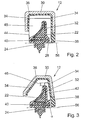
- a wiper arm 10 is made of a joint part 12 and a wiper rod 14 constructed, with a wiper blade 20 via a joint 18 and a connecting piece 16 is connected (Fig. 1).
- the wiper blade 20 has an elastic, joint-free Wischleistenlism 22, which is designed as a spoiler and a wiper strip 24 carries.
- the joint 18 between the wiper rod 14 and the wiper blade 20 and the elasticity of the wiper strip carrier 22 allow the wiper strip 24 during the wiping movement of the curvature of a windshield 26 can adjust. This moves Wiper blade 20 in a plane perpendicular to the windshield 26 relative to the wiper arm 10, wherein the relative lifting movement on End of the wiper blade 20 is particularly large.
- a wiper blade guide intended for lateral guidance of the wiper blade 20 is at the end, which faces the wiper arm 10, a wiper blade guide intended. It consists of an end cap 28 with the side molded guide ribs 48, which are transverse to the longitudinal direction 58th of the wiper blade 20, and from the joint part 12 with an inserted guide bracket 36, which serves as a contact surface for the guide ribs 48 is used.
- the end cap 28 made of plastic includes the wiper carrier 22 and a part of the wiper strip 24 together with two spring rails 40 made of spring steel, which are inserted in lateral longitudinal grooves of the profile (Fig. 2). It forms a cover of the wiper blade 20 in the end region and simultaneously fixes the spring rails 40 axially and together with the connector 16 laterally.
- the guide ribs 48 are formed during manufacture to the end cap. They have lateral guide surfaces 44 which are perpendicular to a base 56 of the end cap 28 extend and mounted in the Condition in profile of the wiper arm 10, e.g. under interposition a guide bracket 36 on the two side walls 34 of the joint part 12 are guided.
- the hinge part 12 has a U-shaped cross-sectional profile.
- the guide bracket 36 is also a plastic part. He dresses the inner contour of the joint part 12 in Area of the end cap 28 and is supported on the side walls 34 and on the top wall 30 from.
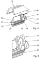
- the guide ribs 42 and 50 are only on one side part 32 of the end cap 28 guide ribs 42 and 50 with guide surfaces 44 and 54 integrally formed (Fig.3 to Fig. 6). Furthermore the guide surfaces 44 an inclination angle ⁇ to Base 56 on, the slightly smaller 90 ° and the inclination the side wall 34 of the joint part 12 is adjusted.
- End cap 28 is associated with a wiper arm 10, the hinge part 12 a roof-shaped cross-sectional profile with different inclined side walls 34 has.
- the inclination the guide surfaces 44 is adapted to the steeper side wall 34 and the guide ribs 42 are in the mounted position on this side wall 34 at. In a parking position of the wiper arm 10, the flatter side wall 34 down and acts in wiping operation as a spoiler.
- the guide bracket 36 in the hinge part 12 used, for example, clipped, clamped or glued.
- the hinge part 12 in a simple way and only changed in the area of the dipping end cap 28 and Incidentally, this corresponds to the standard version.
- a Wiper arm 10 also subsequently with such a wiper blade guide be equipped.
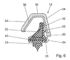
- the guide bracket is provided 36 of a metallic material and the guide ribs 50 are shortened relative to the height of the end cap 28.
- This end cap 28 lies in an area with the guide surfaces 54 and in another area with their upper one Part on the guide bracket 36 at. The transition between two areas is formed by a throat 52.
Landscapes
- Engineering & Computer Science (AREA)
- Mechanical Engineering (AREA)
- Ink Jet (AREA)
- Body Structure For Vehicles (AREA)
- Window Of Vehicle (AREA)
Description
- Fig. 1
- eine schematische Seitenansicht eines Wischarms mit einem gelenkig verbunden Wischblatt,
- Fig. 2
- einen Schnitt entsprechend der Linie II-II in Fig. 1,
- Fig. 3
- eine Variante zu Fig. 2
- Fig. 4
- eine perspektivische Teilansicht von Fig. 3 in einer geänderten relativen Lage zwischen einem Gelenkteil und einem Wischblatt,
- Fig. 5
- eine vergrößerte perspektivische Darstellung einer Endkappe nach Fig. 4 und
- Fig. 6
- eine weitere Variante nach Fig. 2.
- 10
- Wischarm
- 12
- Gelenkteil
- 14
- Wischstange
- 16
- Verbindungsstück
- 18
- Gelenk
- 20
- Wischblatt
- 22
- Wischleistenträger
- 24
- Wischleiste
- 26
- Windschutzscheibe
- 28
- Endkappe
- 30
- Deckwand
- 32
- Seitenteil
- 34
- Seitenwand
- 36
- Führungsbügel
- 38
- Teil
- 40
- Federschiene
- 42
- Führungsrippe
- 44
- Führungsfläche
- 46
- Bereich
- 48
- Führungsrippe
- 50
- Führungsrippe
- 52
- Kehle
- 54
- Führungsfläche
- 56
- Grundfläche
- 58
- Längsrichtung
Claims (8)
- Wischblatt (20) eines Scheibenwischers mit einem Wischleistenträger (22) und einer Wischleiste (24), die an ihren Enden Endkappen (28) aufweisen, deren inneres Querschnittprofil dem Querschnittprofil des Wischleistenträgers (22) angepasst ist, dadurch gekennzeichnet, dass an mindestens einer der Endkappen (28) eine quer zur Längsrichtung (58) des Wischblatts (20) verlaufende Führungsrippe (42, 48, 50) mit einer Führungsfläche (44, 54) seitlich angeformt ist.
- Wischblatt (20) nach Anspruch 1, dadurch gekennzeichnet, dass es einem Wischarm (10) zuzuordnen ist, der ein u-förmiges Querschnittprofil aufweist, in dem die Endkappe (28) in montierter Stellung durch Führungsrippen (48) auf beiden Seiten an den Seitenwänden (34) geführt ist.
- Wischblatt (20) nach Anspruch 1, dadurch gekennzeichnet, dass es einem Wischarm (10) zuzuordnen ist, der ein dachförmiges Querschnittprofil mit einer steileren Seitenwand (34) aufweist, wobei die Führungsfläche (44, 54) an der einseitig angeformten Führungsrippe (42, 50) in montierter Stellung nur an der steileren Seitenwand (34) geführt ist und die Neigung der Führungsfläche (44, 54) der Neigung der Seitenwand (34) angepasst ist.
- Wischblatt (20) nach Anspruch 3, dadurch gekennzeichnet, dass die Führungsfläche (44, 54) zu einer Grundfläche (56) einen Neigungswinkel aufweist, der geringfügig kleiner 90° ist.
- Wischblatt (20) nach einem der vorhergehenden Ansprüche, dadurch gekennzeichnet, dass die Führungsrippe (42, 48) an der Seite, die der Grundfläche (56) abgewandt ist, das äußere Profil der Endkappe (28) um einen Bereich (46) überragt.
- Wischblatt (20) nach einem der Ansprüche 3 oder 4, dadurch gekennzeichnet, dass die Führungsrippe (50) gegenüber der Höhe der Endkappe (28) so verkürzt ist, das die Endkappe (28) mit ihrem oberen Teil die Innenkontur des Wischarms (10) berührt.
- Wischblatt (20) nach Ansprüche 2 bis 6, dadurch gekennzeichnet, dass in dem Wischarm (10) ein Führungsbügel (36) aus Kunststoff eingesetzt ist, der als Anlagefläche für die Führungsfläche (44, 54) dient.
- Wischblatt (20) nach Anspruch 7, dadurch gekennzeichnet, dass der Führungsbügel (36) aus Kunststoff die der Führungsfläche (44, 54) zugewandte Seitenwand (34) des Wischarms (10) im Querschnitt verlängert.
Applications Claiming Priority (3)
| Application Number | Priority Date | Filing Date | Title |
|---|---|---|---|
| DE10218033A DE10218033A1 (de) | 2002-04-23 | 2002-04-23 | Wischblatt |
| DE10218033 | 2002-04-23 | ||
| PCT/DE2003/001232 WO2003091078A1 (de) | 2002-04-23 | 2003-04-11 | Wischblatt |
Publications (2)
| Publication Number | Publication Date |
|---|---|
| EP1501710A1 EP1501710A1 (de) | 2005-02-02 |
| EP1501710B1 true EP1501710B1 (de) | 2005-09-14 |
Family
ID=29264779
Family Applications (1)
| Application Number | Title | Priority Date | Filing Date |
|---|---|---|---|
| EP03747077A Expired - Lifetime EP1501710B1 (de) | 2002-04-23 | 2003-04-11 | Wischblatt |
Country Status (6)
| Country | Link |
|---|---|
| US (1) | US7509704B2 (de) |
| EP (1) | EP1501710B1 (de) |
| JP (1) | JP4154343B2 (de) |
| DE (2) | DE10218033A1 (de) |
| ES (1) | ES2247556T3 (de) |
| WO (1) | WO2003091078A1 (de) |
Cited By (5)
| Publication number | Priority date | Publication date | Assignee | Title |
|---|---|---|---|---|
| US8806700B2 (en) | 2011-07-29 | 2014-08-19 | Pylon Manufacturing Corporation | Wiper blade connector |
| US9108595B2 (en) | 2011-07-29 | 2015-08-18 | Pylon Manufacturing Corporation | Windshield wiper connector |
| US9457768B2 (en) | 2011-04-21 | 2016-10-04 | Pylon Manufacturing Corp. | Vortex damping wiper blade |
| US9505380B2 (en) | 2014-03-07 | 2016-11-29 | Pylon Manufacturing Corp. | Windshield wiper connector and assembly |
| USD777079S1 (en) | 2014-10-03 | 2017-01-24 | Pylon Manufacturing Corp. | Wiper blade frame |
Families Citing this family (24)
| Publication number | Priority date | Publication date | Assignee | Title |
|---|---|---|---|---|
| DE10218033A1 (de) * | 2002-04-23 | 2003-11-20 | Bosch Gmbh Robert | Wischblatt |
| US20060207050A1 (en) * | 2004-07-30 | 2006-09-21 | Subramaniam Shanmugham | Windshield wiper structure |
| JP4981626B2 (ja) * | 2007-11-09 | 2012-07-25 | 株式会社ミツバ | 車両用ワイパ装置 |
| DE102009028910A1 (de) * | 2009-08-05 | 2011-02-10 | Robert Bosch Gmbh | Wischblatt in Flachbalkenbauweise |
| US8495787B2 (en) | 2010-08-03 | 2013-07-30 | Rally Manufacturing, Inc. | Windshield wiper |
| USD706200S1 (en) | 2010-09-22 | 2014-06-03 | Pylon Manufacturing Corporation | Windshield wiper cover |
| DE102010062274B4 (de) * | 2010-12-01 | 2021-12-23 | Robert Bosch Gmbh | Wischblatt in Flachbalkenbauweise |
| US9174609B2 (en) | 2011-04-21 | 2015-11-03 | Pylon Manufacturing Corp. | Wiper blade with cover |
| CA2843527C (en) | 2011-07-28 | 2018-11-27 | Pylon Manufacturing Corp. | Windshield wiper adapter, connector and assembly |
| WO2013019645A1 (en) | 2011-07-29 | 2013-02-07 | Pylon Manufacturing Corp. | Windshield wiper connector |
| KR101775660B1 (ko) | 2011-09-29 | 2017-09-07 | 삼성전자주식회사 | 워드 라인 전압의 변화없이 상이한 문턱 전압들을 갖는 메모리 셀들을 읽는 방법 및 그것을 이용한 불 휘발성 메모리 장치 |
| MX385411B (es) | 2012-02-24 | 2025-03-18 | Pylon Mfg Corp | Escobilla limpiaparabrisas. |
| US20130219649A1 (en) | 2012-02-24 | 2013-08-29 | Pylon Manufacturing Corp. | Wiper blade |
| US10723322B2 (en) | 2012-02-24 | 2020-07-28 | Pylon Manufacturing Corp. | Wiper blade with cover |
| US10829092B2 (en) | 2012-09-24 | 2020-11-10 | Pylon Manufacturing Corp. | Wiper blade with modular mounting base |
| US10166951B2 (en) | 2013-03-15 | 2019-01-01 | Pylon Manufacturing Corp. | Windshield wiper connector |
| USD787308S1 (en) | 2014-10-03 | 2017-05-23 | Pylon Manufacturing Corp. | Wiper blade package |
| JP6411916B2 (ja) * | 2015-02-26 | 2018-10-24 | ラピスセミコンダクタ株式会社 | 半導体装置、ワイパシステム、及び移動体制御方法 |
| US10363905B2 (en) | 2015-10-26 | 2019-07-30 | Pylon Manufacturing Corp. | Wiper blade |
| AU2017268008A1 (en) | 2016-05-19 | 2018-11-22 | Pylon Manufacturing Corp. | Windshield wiper connector |
| EP3458315B1 (de) | 2016-05-19 | 2021-09-08 | Pylon Manufacturing Corp. | Scheibenwischerblatt |
| CN109311452A (zh) | 2016-05-19 | 2019-02-05 | 电缆塔制造有限公司 | 挡风玻璃雨刮器连接器 |
| CN109311450A (zh) | 2016-05-19 | 2019-02-05 | 电缆塔制造有限公司 | 挡风玻璃雨刮器连接器 |
| US11040705B2 (en) | 2016-05-19 | 2021-06-22 | Pylon Manufacturing Corp. | Windshield wiper connector |
Citations (1)
| Publication number | Priority date | Publication date | Assignee | Title |
|---|---|---|---|---|
| WO2000034090A1 (de) * | 1998-12-07 | 2000-06-15 | Robert Bosch Gmbh | Wischblatt für scheiben von kraftfahrzeugen |
Family Cites Families (14)
| Publication number | Priority date | Publication date | Assignee | Title |
|---|---|---|---|---|
| CH624349A5 (de) | 1978-12-05 | 1981-07-31 | J B Brevets | |
| US4442566A (en) * | 1981-11-06 | 1984-04-17 | Parker-Hannifin Corporation | Windshield wiper blade refill unit |
| DE3744237A1 (de) | 1987-12-24 | 1989-07-06 | Swf Auto Electric Gmbh | Scheibenwischer und fuehrungselement fuer einen scheibenwischer |
| DE3829343C2 (de) * | 1988-08-30 | 1996-03-21 | Teves Gmbh Alfred | Wischblatt, insbesondere für Wischanlagen an Kraftfahrzeugen |
| US5325561A (en) * | 1989-07-05 | 1994-07-05 | Kotlar Edward A | Heated flexible windshield wiper |
| US5327615A (en) * | 1993-02-16 | 1994-07-12 | Green Gerald D | Windshield wiper blade assembly including conical cleaning tips |
| DE19647347A1 (de) | 1996-11-15 | 1998-05-20 | Teves Gmbh Alfred | Wischhebel einer Fahrzeugscheibenwischervorrichtung |
| DE19731683A1 (de) * | 1997-07-23 | 1999-01-28 | Bosch Gmbh Robert | Scheibenwischer |
| DE19738232A1 (de) | 1997-09-02 | 1999-03-04 | Bosch Gmbh Robert | Tragelement für eine zu einem Wischblatt für Scheiben von Kraftfahrzeugen gehörenden Wischleiste und Verfahren zu dessen Herstellung |
| US6038730A (en) * | 1998-08-10 | 2000-03-21 | Chen; Liang-Yuan | Windshield wiper with replacement blade |
| DE10120467A1 (de) * | 2001-04-26 | 2002-10-31 | Bosch Gmbh Robert | Wischblatt zum Reinigen von Scheiben, insbesondere von Kraftfahrzeugen |
| DE10142997A1 (de) * | 2001-09-01 | 2003-03-27 | Bosch Gmbh Robert | Wischarm mit einem gelenkig verbundenen Wischblatt |
| DE10218033A1 (de) * | 2002-04-23 | 2003-11-20 | Bosch Gmbh Robert | Wischblatt |
| ES2294431T3 (es) * | 2004-03-09 | 2008-04-01 | Federal-Mogul S.A. | Brazo de limpiaparabrisas. |
-
2002
- 2002-04-23 DE DE10218033A patent/DE10218033A1/de not_active Withdrawn
-
2003
- 2003-04-11 ES ES03747077T patent/ES2247556T3/es not_active Expired - Lifetime
- 2003-04-11 DE DE50301200T patent/DE50301200D1/de not_active Expired - Lifetime
- 2003-04-11 EP EP03747077A patent/EP1501710B1/de not_active Expired - Lifetime
- 2003-04-11 US US10/508,231 patent/US7509704B2/en not_active Expired - Fee Related
- 2003-04-11 WO PCT/DE2003/001232 patent/WO2003091078A1/de not_active Ceased
- 2003-04-11 JP JP2003587661A patent/JP4154343B2/ja not_active Expired - Fee Related
Patent Citations (1)
| Publication number | Priority date | Publication date | Assignee | Title |
|---|---|---|---|---|
| WO2000034090A1 (de) * | 1998-12-07 | 2000-06-15 | Robert Bosch Gmbh | Wischblatt für scheiben von kraftfahrzeugen |
Cited By (5)
| Publication number | Priority date | Publication date | Assignee | Title |
|---|---|---|---|---|
| US9457768B2 (en) | 2011-04-21 | 2016-10-04 | Pylon Manufacturing Corp. | Vortex damping wiper blade |
| US8806700B2 (en) | 2011-07-29 | 2014-08-19 | Pylon Manufacturing Corporation | Wiper blade connector |
| US9108595B2 (en) | 2011-07-29 | 2015-08-18 | Pylon Manufacturing Corporation | Windshield wiper connector |
| US9505380B2 (en) | 2014-03-07 | 2016-11-29 | Pylon Manufacturing Corp. | Windshield wiper connector and assembly |
| USD777079S1 (en) | 2014-10-03 | 2017-01-24 | Pylon Manufacturing Corp. | Wiper blade frame |
Also Published As
| Publication number | Publication date |
|---|---|
| ES2247556T3 (es) | 2006-03-01 |
| WO2003091078A1 (de) | 2003-11-06 |
| DE10218033A1 (de) | 2003-11-20 |
| JP2005523202A (ja) | 2005-08-04 |
| US7509704B2 (en) | 2009-03-31 |
| US20050138751A1 (en) | 2005-06-30 |
| JP4154343B2 (ja) | 2008-09-24 |
| EP1501710A1 (de) | 2005-02-02 |
| DE50301200D1 (de) | 2005-10-20 |
Similar Documents
| Publication | Publication Date | Title |
|---|---|---|
| EP1501710B1 (de) | Wischblatt | |
| EP1363816B1 (de) | Wischarm mit einem gelenkig verbundenen wischblatt | |
| EP2271524B1 (de) | Vorrichtung zum gelenkigen verbinden eines wischblatts mit einem wischarm | |
| EP1322507B1 (de) | Scheibenwischer | |
| EP0935546B1 (de) | Wischblatt zum reinigen von scheiben von kraftfahrzeugen | |
| EP0928263B1 (de) | Scheibenwischer | |
| EP1877290B1 (de) | Wischarm mit einem wischblatt | |
| DE10157130A1 (de) | Wischarm mit einem gelenkig verbundenen Wischblatt | |
| EP1485279B1 (de) | Vorrichtung zum seitlichen f hren eines wischblatts | |
| DE102011102408A1 (de) | Scheibenwischer mit zumindest zwei schwenkbar an einem Wischarm angeordneten Wischlippen | |
| DE10309080B4 (de) | Wischblatt | |
| EP1575813B1 (de) | Wischebel mit einem wischarm und einem wischblatt | |
| EP1029758B1 (de) | Wischanlage | |
| DE69206329T2 (de) | Scheibenwischer für ein Kraftfahrzeug, versehen mit einem aerodynamischen Windabweiser. | |
| DE69601966T2 (de) | Kraftfahrzeug-Scheibenwischer mit Wischerarm mit angeformter Hebevorrichtung | |
| DE10340139B4 (de) | Gelenkverbindung | |
| EP3172095B1 (de) | Quickfix für finray-wischer | |
| DE112014003093B4 (de) | Universalverbindungsanordnung | |
| DE102008010564B4 (de) | Wischerblatt für ein Fahrzeug | |
| EP1844995B1 (de) | Scheibenwischer | |
| DE102004012867B4 (de) | Scheibenwischer für die Scheibenwischeranlage an einem Fahrzeug | |
| EP1666320B1 (de) | Wischblatt | |
| DE19811859B4 (de) | Wischervorrichtung | |
| DE112013005446T5 (de) | Luftleitelement fur eine Wischeranordnung | |
| DE102005024718A1 (de) | Wischblatt |
Legal Events
| Date | Code | Title | Description |
|---|---|---|---|
| PUAI | Public reference made under article 153(3) epc to a published international application that has entered the european phase |
Free format text: ORIGINAL CODE: 0009012 |
|
| 17P | Request for examination filed |
Effective date: 20041123 |
|
| AK | Designated contracting states |
Kind code of ref document: A1 Designated state(s): AT BE BG CH CY CZ DE DK EE ES FI FR GB GR HU IE IT LI LU MC NL PT RO SE SI SK TR |
|
| GRAP | Despatch of communication of intention to grant a patent |
Free format text: ORIGINAL CODE: EPIDOSNIGR1 |
|
| GRAS | Grant fee paid |
Free format text: ORIGINAL CODE: EPIDOSNIGR3 |
|
| GRAA | (expected) grant |
Free format text: ORIGINAL CODE: 0009210 |
|
| AK | Designated contracting states |
Kind code of ref document: B1 Designated state(s): DE ES FR GB IT |
|
| REG | Reference to a national code |
Ref country code: GB Ref legal event code: FG4D Free format text: NOT ENGLISH |
|
| REF | Corresponds to: |
Ref document number: 50301200 Country of ref document: DE Date of ref document: 20051020 Kind code of ref document: P |
|
| GBT | Gb: translation of ep patent filed (gb section 77(6)(a)/1977) |
Effective date: 20060104 |
|
| REG | Reference to a national code |
Ref country code: ES Ref legal event code: FG2A Ref document number: 2247556 Country of ref document: ES Kind code of ref document: T3 |
|
| ET | Fr: translation filed | ||
| PLBE | No opposition filed within time limit |
Free format text: ORIGINAL CODE: 0009261 |
|
| STAA | Information on the status of an ep patent application or granted ep patent |
Free format text: STATUS: NO OPPOSITION FILED WITHIN TIME LIMIT |
|
| 26N | No opposition filed |
Effective date: 20060615 |
|
| PGFP | Annual fee paid to national office [announced via postgrant information from national office to epo] |
Ref country code: IT Payment date: 20120424 Year of fee payment: 10 |
|
| PGFP | Annual fee paid to national office [announced via postgrant information from national office to epo] |
Ref country code: ES Payment date: 20120423 Year of fee payment: 10 |
|
| PG25 | Lapsed in a contracting state [announced via postgrant information from national office to epo] |
Ref country code: IT Free format text: LAPSE BECAUSE OF NON-PAYMENT OF DUE FEES Effective date: 20130411 |
|
| REG | Reference to a national code |
Ref country code: ES Ref legal event code: FD2A Effective date: 20140610 |
|
| PG25 | Lapsed in a contracting state [announced via postgrant information from national office to epo] |
Ref country code: ES Free format text: LAPSE BECAUSE OF NON-PAYMENT OF DUE FEES Effective date: 20130412 |
|
| REG | Reference to a national code |
Ref country code: FR Ref legal event code: PLFP Year of fee payment: 14 |
|
| REG | Reference to a national code |
Ref country code: FR Ref legal event code: PLFP Year of fee payment: 15 |
|
| REG | Reference to a national code |
Ref country code: FR Ref legal event code: PLFP Year of fee payment: 16 |
|
| PGFP | Annual fee paid to national office [announced via postgrant information from national office to epo] |
Ref country code: FR Payment date: 20200421 Year of fee payment: 18 |
|
| REG | Reference to a national code |
Ref country code: DE Ref legal event code: R084 Ref document number: 50301200 Country of ref document: DE |
|
| PGFP | Annual fee paid to national office [announced via postgrant information from national office to epo] |
Ref country code: GB Payment date: 20200423 Year of fee payment: 18 |
|
| GBPC | Gb: european patent ceased through non-payment of renewal fee |
Effective date: 20210411 |
|
| PG25 | Lapsed in a contracting state [announced via postgrant information from national office to epo] |
Ref country code: FR Free format text: LAPSE BECAUSE OF NON-PAYMENT OF DUE FEES Effective date: 20210430 Ref country code: GB Free format text: LAPSE BECAUSE OF NON-PAYMENT OF DUE FEES Effective date: 20210411 |
|
| PGFP | Annual fee paid to national office [announced via postgrant information from national office to epo] |
Ref country code: DE Payment date: 20220627 Year of fee payment: 20 |
|
| REG | Reference to a national code |
Ref country code: DE Ref legal event code: R071 Ref document number: 50301200 Country of ref document: DE |