EP1501690B1 - Method of decorating large plastic 3d objects - Google Patents
Method of decorating large plastic 3d objects Download PDFInfo
- Publication number
- EP1501690B1 EP1501690B1 EP02758198A EP02758198A EP1501690B1 EP 1501690 B1 EP1501690 B1 EP 1501690B1 EP 02758198 A EP02758198 A EP 02758198A EP 02758198 A EP02758198 A EP 02758198A EP 1501690 B1 EP1501690 B1 EP 1501690B1
- Authority
- EP
- European Patent Office
- Prior art keywords
- thermal transfer
- molded article
- transfer foil
- foil
- molded
- Prior art date
- Legal status (The legal status is an assumption and is not a legal conclusion. Google has not performed a legal analysis and makes no representation as to the accuracy of the status listed.)
- Expired - Lifetime
Links
Images








Classifications
-
- B—PERFORMING OPERATIONS; TRANSPORTING
- B44—DECORATIVE ARTS
- B44C—PRODUCING DECORATIVE EFFECTS; MOSAICS; TARSIA WORK; PAPERHANGING
- B44C1/00—Processes, not specifically provided for elsewhere, for producing decorative surface effects
- B44C1/10—Applying flat materials, e.g. leaflets, pieces of fabrics
-
- B—PERFORMING OPERATIONS; TRANSPORTING
- B29—WORKING OF PLASTICS; WORKING OF SUBSTANCES IN A PLASTIC STATE IN GENERAL
- B29C—SHAPING OR JOINING OF PLASTICS; SHAPING OF MATERIAL IN A PLASTIC STATE, NOT OTHERWISE PROVIDED FOR; AFTER-TREATMENT OF THE SHAPED PRODUCTS, e.g. REPAIRING
- B29C37/00—Component parts, details, accessories or auxiliary operations, not covered by group B29C33/00 or B29C35/00
- B29C37/0025—Applying surface layers, e.g. coatings, decorative layers, printed layers, to articles during shaping, e.g. in-mould printing
-
- B—PERFORMING OPERATIONS; TRANSPORTING
- B29—WORKING OF PLASTICS; WORKING OF SUBSTANCES IN A PLASTIC STATE IN GENERAL
- B29C—SHAPING OR JOINING OF PLASTICS; SHAPING OF MATERIAL IN A PLASTIC STATE, NOT OTHERWISE PROVIDED FOR; AFTER-TREATMENT OF THE SHAPED PRODUCTS, e.g. REPAIRING
- B29C63/00—Lining or sheathing, i.e. applying preformed layers or sheathings of plastics; Apparatus therefor
- B29C63/0073—Lining or sheathing, i.e. applying preformed layers or sheathings of plastics; Apparatus therefor of non-flat surfaces, e.g. curved, profiled
-
- B—PERFORMING OPERATIONS; TRANSPORTING
- B44—DECORATIVE ARTS
- B44C—PRODUCING DECORATIVE EFFECTS; MOSAICS; TARSIA WORK; PAPERHANGING
- B44C1/00—Processes, not specifically provided for elsewhere, for producing decorative surface effects
- B44C1/16—Processes, not specifically provided for elsewhere, for producing decorative surface effects for applying transfer pictures or the like
- B44C1/165—Processes, not specifically provided for elsewhere, for producing decorative surface effects for applying transfer pictures or the like for decalcomanias; sheet material therefor
- B44C1/17—Dry transfer
- B44C1/1712—Decalcomanias applied under heat and pressure, e.g. provided with a heat activable adhesive
-
- B—PERFORMING OPERATIONS; TRANSPORTING
- B44—DECORATIVE ARTS
- B44C—PRODUCING DECORATIVE EFFECTS; MOSAICS; TARSIA WORK; PAPERHANGING
- B44C1/00—Processes, not specifically provided for elsewhere, for producing decorative surface effects
- B44C1/16—Processes, not specifically provided for elsewhere, for producing decorative surface effects for applying transfer pictures or the like
- B44C1/165—Processes, not specifically provided for elsewhere, for producing decorative surface effects for applying transfer pictures or the like for decalcomanias; sheet material therefor
- B44C1/17—Dry transfer
- B44C1/1712—Decalcomanias applied under heat and pressure, e.g. provided with a heat activable adhesive
- B44C1/1729—Hot stamping techniques
-
- B—PERFORMING OPERATIONS; TRANSPORTING
- B29—WORKING OF PLASTICS; WORKING OF SUBSTANCES IN A PLASTIC STATE IN GENERAL
- B29C—SHAPING OR JOINING OF PLASTICS; SHAPING OF MATERIAL IN A PLASTIC STATE, NOT OTHERWISE PROVIDED FOR; AFTER-TREATMENT OF THE SHAPED PRODUCTS, e.g. REPAIRING
- B29C2793/00—Shaping techniques involving a cutting or machining operation
-
- B—PERFORMING OPERATIONS; TRANSPORTING
- B29—WORKING OF PLASTICS; WORKING OF SUBSTANCES IN A PLASTIC STATE IN GENERAL
- B29L—INDEXING SCHEME ASSOCIATED WITH SUBCLASS B29C, RELATING TO PARTICULAR ARTICLES
- B29L2031/00—Other particular articles
- B29L2031/722—Decorative or ornamental articles
Definitions
- the present invention relates to a method used for the decoration of plastic molded articles, and relates to a thermal transfer technique and the so-called three-dimensional hot stamp decoration technique, which performs decoration by causing a thermal transfer foil to cover a surface of a large plastic molded article having a three-dimensional shape; clamping the perimeter of the thermal transfer foil; attaching the foil to the molded article shape by means of vacuum degassing; and thereafter lowering and raising a molded rubber mold.
- molded article As methods for decorating a surface of a large plastic molded article (referred to as "molded article” hereinafter), methods exist which perform decoration by transferring a thermal transfer foil design to a surface of a molded article by causing a thermal transfer foil to cover a molded article; pressing the perimeter of the thermal transfer foil; attaching the thermal transfer foil to the molded article by means of vacuum extraction, whereupon the foil adopts a shape like that of the molded article; and lowering and raising a heated "molded rubber mold”.
- This method is known as three-dimensional hot stamping. This technique will be described in detail hereinbelow using specific examples.
- a molded article such as that illustrated in Fig. 1 is presented as an article for decoration.
- the dimensions of this molded article are: length 900 mm, width 300 mm, height 50 mm, and wall face height 25 mm.
- an outside view and a cross-sectional view of the molded rubber mold for hot stamping are shown in Figs. 2, 3.
- a bar-shaped heater 9 is fitted thereon, and [the molded rubber mold with heater] is mounted on a stamp device which has a lowering and raising mechanism as shown in Fig. 4.
- This stamp device has a slide table 4 on whose inner face a support jig 5, which is for securing a product made of aluminum manufactured so as to match the shape of the molded article (referred to as "support jig" hereinafter), is arranged.
- the mold support jig and device as described above, first the molded article 6 is fixed to the top of the support jig 5 as shown in Fig. 4. Thereupon, a thermal transfer foil 7 is set using a foil chuck over a space into which the slide table is to be introduced once. Next, the slide table is moved to below the molded rubber mold as far as the state in Fig. 5, and the thermal transfer foil 7 is secured by lowering the foil clamp 8. Then, cutting of the thermal transfer foil 7 on the roll side is performed using a foil cutter. Next, by removing the air in an enclosure 10 contained by the support jig 5 and the molded article 6, using a vacuum pump, the thermal transfer foil 7 is caused to adhere to the molded article 6.
- the thermal transfer foil 7 Following adequate adhesion of the thermal transfer foil 7, heat and pressure are applied by lowering the molded rubber mold 3 as shown in Fig. 6, such that the design is transferred to the molded article 6. Thereafter, after raising the molded rubber mold 3 as shown in Fig. 7, the position of the slide table 4 is moved as shown in Fig. 8, and after peeling the thermal transfer foil 7 from the surface of the molded article 6, the molded article 6 thus decorated is removed.
- the peeling of the thermal transfer foil 7 may also be performed following removal of the molded article 6 from the support jig 5. Following peeling of the thermal transfer foil 7, in cases where foil burrs remain on the grating portions, the grating portions are rubbed using a sponge, and then, by running a cleaner, finishing of the decorated article is performed.
- thermal transfer foil 7 is supplied continuously using a foil roll, and the thermal transfer foil 7 is peeled in foil peeling bars after transfer have also already been implemented as mass production methods.
- the molded rubber mold makes contact with the thermal transfer foil at the perimeter of the molded article before reaching the drop point, that is, the molded article surface, and the thermal transfer foil is tom (referred to as foil splitting hereinafter).
- foil splitting the thermal transfer foil is tom
- a side upright portion is of a comparatively undulating shape, where the angle ⁇ is an obtuse angle, as shown in Figs. 9 to 12.
- thermal transfer foil For a long time, methods have been considered which position the thermal transfer foil below a molded rubber mold, perform adequate heating, and make it easier to extend the thermal transfer foil during vacuum extraction. Nevertheless, because the thermal transfer foil makes contact with the molded article after the clamping plate has dropped, the thermal transfer foil is cooled instantly, Also, the thermal deformation temperature of the molded article (HIPS, ABS) is generally equal to or less than 100°C, and since this is lower than 120°C, which is the thermal deformation temperature of the foil (PET film), it is not possible to heat the thermal transfer foil and the molded article together during vacuum extraction. As above, during vacuum extraction, heating and extending the PET film alone using a shape rubber mold was difficult.
- GB-A 2 345 661 describes a decoration method wherein a foil is transferred by means of a membrane press to an article which shall be decorated.
- a foil carrying sheet is placed over the article to be decorated against the surface to which a foil is to be transferred.
- the article and the foil arranged thereon is moved into the pressing area and the membrane of the membrane press is pressed over the arrangement. Thereby the arrangement is sealed by the overlapping edge of the membrane of the membrane press.
- US-A 5,125,994 describes a method for bounding a thermoplastic film to a three-dimensional substrate, wherein said thermoplastic foil is clamped in a frame, placed over the substrate and is heated in the whole area which has to be bounded to the substrate by means of a heater.
- the thermoplastic film according to US-A 5,125,994 is a foil arranged of a clear coat layer, a decorative paint layer, a tie-layer, a carrier film and a pressure sensitive adhesive layer.
- the carrier is an integral part of the foil and cannot be removed from the decorative article at the last step of the decoration process.
- the present inventors arrived at the invention of a method for decorating the surface of a large plastic molded article having a deeper three-dimensional shape, using a thermal transfer foil and a molded rubber mold.
- This invention corresponds to the shape in Fig. 13 to Fig. 16, but, as shown in Figs. 24 and 25, a planar heater 17 is provided at the side of the support jig of the side portions of the molded article 6. By heating the thermal transfer foil using this planar heater 17, during vacuum extraction, the thermal transfer foil is partially heated, extended, and caused to adhere to the molded article.
- the molded rubber mold may have a conventional constitution.
- a shape cutter is fixed to a side portion of the molded rubber mold and a mechanism is mounted that cuts the thermal transfer foil before the molded rubber mold reaches the drop point.
- a lubricant such as silicon grease is applied.
- the present invention having the constitution described above, the following actions were identified in the hot stamp decoration of a plastic molded article possessing three-dimensional curved faces of a deep shape.
- the thermal transfer foil by using a planar heater to heat the thermal transfer foil in the vicinity of the portion which is to be caused to adhere to a molded article, the thermal transfer foil extends partially, and, conjointly with vacuum extraction, it is possible to cause the thermal transfer foil to adhere to the sides of a deeper shape.
- the thermal transfer foil which has been extended to its limit using vacuum extraction, immediately before the molded rubber mold reaches the drop point.
- the tensile strength of the thermal transfer foil is zero, and a molded rubber mold with a deep shape like that shown in Fig. 26 is then covered, the thermal transfer foil is extended to its limit, and, thereafter, even if the thermal transfer foil contracts once again, foil recovery; is not observed.
- the thermal transfer foil adheres as far as the edges of the molded article and it is possible to prevent collision between the molded rubber mold and the foil part R when the molded rubber mold drops, whereby favorable decoration can be performed.
- h 1 ... the side total height
- h 2 ... the side face height
- ⁇ ° ... the side angle which are appended to the molded article side shapes shown in Figs. 9 to 12, Figs. 13 to 16, and Figs. 17 to 20, are shown in a table in Fig. 36.
- the molded article possesses the shape shown in Fig. 6 and is an air conditioner grill.
- the dimensions of this molded article are: length 800 mm, width 200 mm, height 44 mm, and wall face height 23 mm.
- a planar heater 17 (referred to as “side heater” hereinafter) is provided at the side of the molded article 6, when vacuum extraction is performed, since the thermal transfer foil 7 is partially heated and extended, it is possible to cause the thermal transfer foil 7 to adhere as far as the edges of the molded article 6.
- the thermal transfer foil 7 is torn, and vacuum breakage results.
- parts of the molded rubber 3 are heated to 180°C, when collision is with free parts of the thermal transfer foil 7 which is produced using polyethylene terephthalate film, the thermal transfer foil 7 is instantly damaged.
- the molded article is an air conditioner grill possessing the shape shown in Figs. 17 to 20.
- the dimensions of this molded article are: length 800 mm, width 270 mm, height 115 mm, and wall face height 30 mm.
- Fig. 86 when the molded article has a shape in which the side wall angle ⁇ is extremely small, even if the thermal transfer foil 7 is extended partially using the planar heater 17 such that same is attached to the edges of the molded article 6, ring-shaped cuts like those in Fig. 23 caused by contraction of the thermal transfer foil 7 following thermal transfer decoration no longer remain.
- FIG. 33 A cross-section through the center of the molded article is shown in Fig. 33 as an Example of the second solution.
- the thermal transfer foil 7 adheres to the molded article 6 as a result of vacuum extraction.
- the molded rubber mold 3 is caused to drop, and, when the molded rubber 3 is on the verge of reaching the surface of the molded article 6, the blade edge of the shape cutter 19 makes contact with and cuts the thermal transfer foil 7. Immediately thereafter, the molded rubber 3 reaches the surface of the molded article 6, and the design of the thermal transfer foil 7 is transferred.
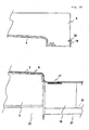
- the thermal transfer foil 7 before cutting, the thermal transfer foil 7 is caused to adhere to the molded article 6 in a state in which there are no wrinkles on same, and since, immediately after cutting, the design is transferred to the molded article by the molded rubber 3 before wrinkles are produced, wrinkles are not observed on the molded article 6 thus decorated. Moreover, when the molded rubber mold 2 is raised, as shown in Fig. 35, since the thermal transfer foil 7 is cut, no ring-shaped cuts due to contraction of the thermal transfer foil 7 which has been forcibly extended were produced on the sides of the molded article. Incidentally, since the thermal transfer foil is cut in this method, a winding method cannot be employed.
Landscapes
- Engineering & Computer Science (AREA)
- Manufacturing & Machinery (AREA)
- Blow-Moulding Or Thermoforming Of Plastics Or The Like (AREA)
- Duplication Or Marking (AREA)
- Decoration By Transfer Pictures (AREA)
Abstract
Description
- The present invention relates to a method used for the decoration of plastic molded articles, and relates to a thermal transfer technique and the so-called three-dimensional hot stamp decoration technique, which performs decoration by causing a thermal transfer foil to cover a surface of a large plastic molded article having a three-dimensional shape; clamping the perimeter of the thermal transfer foil; attaching the foil to the molded article shape by means of vacuum degassing; and thereafter lowering and raising a molded rubber mold.
- As methods for decorating a surface of a large plastic molded article (referred to as "molded article" hereinafter), methods exist which perform decoration by transferring a thermal transfer foil design to a surface of a molded article by causing a thermal transfer foil to cover a molded article; pressing the perimeter of the thermal transfer foil; attaching the thermal transfer foil to the molded article by means of vacuum extraction, whereupon the foil adopts a shape like that of the molded article; and lowering and raising a heated "molded rubber mold". This method is known as three-dimensional hot stamping. This technique will be described in detail hereinbelow using specific examples.
- First, a molded article such as that illustrated in Fig. 1 is presented as an article for decoration. The dimensions of this molded article are: length 900 mm, width 300 mm,
height 50 mm, andwall face height 25 mm. Meanwhile, an outside view and a cross-sectional view of the molded rubber mold for hot stamping are shown in Figs. 2, 3. A bar-shaped heater 9 is fitted thereon, and [the molded rubber mold with heater] is mounted on a stamp device which has a lowering and raising mechanism as shown in Fig. 4. This stamp device has a slide table 4 on whose inner face asupport jig 5, which is for securing a product made of aluminum manufactured so as to match the shape of the molded article (referred to as "support jig" hereinafter), is arranged. - With regard to the mold support jig and device as described above, first the
molded article 6 is fixed to the top of thesupport jig 5 as shown in Fig. 4. Thereupon, athermal transfer foil 7 is set using a foil chuck over a space into which the slide table is to be introduced once. Next, the slide table is moved to below the molded rubber mold as far as the state in Fig. 5, and thethermal transfer foil 7 is secured by lowering thefoil clamp 8. Then, cutting of thethermal transfer foil 7 on the roll side is performed using a foil cutter. Next, by removing the air in anenclosure 10 contained by thesupport jig 5 and the moldedarticle 6, using a vacuum pump, thethermal transfer foil 7 is caused to adhere to the moldedarticle 6. Following adequate adhesion of thethermal transfer foil 7, heat and pressure are applied by lowering the moldedrubber mold 3 as shown in Fig. 6, such that the design is transferred to the moldedarticle 6. Thereafter, after raising the moldedrubber mold 3 as shown in Fig. 7, the position of the slide table 4 is moved as shown in Fig. 8, and after peeling thethermal transfer foil 7 from the surface of the moldedarticle 6, themolded article 6 thus decorated is removed. Of course, the peeling of thethermal transfer foil 7 may also be performed following removal of the moldedarticle 6 from thesupport jig 5. Following peeling of thethermal transfer foil 7, in cases where foil burrs remain on the grating portions, the grating portions are rubbed using a sponge, and then, by running a cleaner, finishing of the decorated article is performed. - In addition, methods in which the
thermal transfer foil 7 is supplied continuously using a foil roll, and thethermal transfer foil 7 is peeled in foil peeling bars after transfer have also already been implemented as mass production methods. - There are limitations on molded article shapes which can be decorated in mass production by performing three-dimensional hot stamping. This is because, with a method of the kind described above, the surface of a large plastic molded article having a three-dimensional shape is decorated by hot stamping using a thermal transfer foil, and since it is necessary to cause a thermal transfer foil, which is a two-dimensional flat surface, to adhere to a molded article with a three-dimensional body structure, the side walls cannot be made very high. When, during vacuum extraction, the molded rubber mold is caused to drop in a state in which the thermal transfer foil does not adhere as far as the side edges, as shown in Fig. 30, the molded rubber mold makes contact with the thermal transfer foil at the perimeter of the molded article before reaching the drop point, that is, the molded article surface, and the thermal transfer foil is tom (referred to as foil splitting hereinafter). As a result, the vacuum is broken, and the thermal transfer foil is no longer in a state of adhesion to the molded article, meaning that uniform decoration can then not be achieved. In concrete terms, there are large adhesion defects and countless wrinkles are produced.
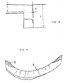
- On account of the state described above, using conventional methods, there are limitations on shapes permitting three-dimensional hot stamp decoration. Since this is judged by combining shape elements, definition is, as a rule, troublesome. However, estimation is possible by combining the following four elements, namely (1) the side wall face shape height h1; (2) the distance h2 from the top of the product to the side edges; (3) the angle α between the side wall face and the horizontal face; and (4) the size of the point of intersection R between the side wall face and the horizontal face.
- Further, since there are also cases where the shape changes gradually, there are also times when, as a rule, the side shape cannot be judged using figures alone.
- For example, one example of a shape which did not generate problems, among shapes which have undergone mass production, may be described in detail using the figures as follows. That is, a side upright portion is of a comparatively undulating shape, where the angle α is an obtuse angle, as shown in Figs. 9 to 12.
- Nevertheless, in accordance with modifications to air conditioner grill designs, products have emerged having a shape in which, as shown in Figs. 13 to 16 and Figs.17 to 20, the distance h2 from the top of the product to the molded article side edges is large, and the side wall face shape depth h1 is deep. Further, there have been a great number of demands from customers for the design decoration of this method to decorate such air conditioner grills with a deeper shape.
- When performing decoration using a conventional method, for the shape of Figs. 9 to 12, it is possible, during vacuum extraction, to cause a thermal transfer foil to adhere as far as the side edges of the molded article, and to uniformly transfer a design to the molded article by causing a molded rubber mold to drop [thereupon].
- However, in the case of the shape in Fig. 13 to 16, it proves difficult for the thermal transfer foil to reach as far as the side edges of the molded article during vacuum extraction, and foil splitting of the kind described above is produced, which means that three-dimensional hot stamp decoration is rendered impossible.
- For a long time, methods have been considered which position the thermal transfer foil below a molded rubber mold, perform adequate heating, and make it easier to extend the thermal transfer foil during vacuum extraction. Nevertheless, because the thermal transfer foil makes contact with the molded article after the clamping plate has dropped, the thermal transfer foil is cooled instantly, Also, the thermal deformation temperature of the molded article (HIPS, ABS) is generally equal to or less than 100°C, and since this is lower than 120°C, which is the thermal deformation temperature of the foil (PET film), it is not possible to heat the thermal transfer foil and the molded article together during vacuum extraction. As above, during vacuum extraction, heating and extending the PET film alone using a shape rubber mold was difficult.
- Also with the molded articles of the shape in Figs. 17 to 20, before the molded rubber mold drops to cause the thermal transfer of the foil design, in other words, before the molded rubber mold reaches the drop point, the molded rubber mold makes contact with the extended thermal transfer foil, and, as a result of the foil being tom thereby, vacuum breakage then occurs, the design transfer itself becomes impossible, and adhesion defects and wrinkles are produced as shown in Fig. 21. Further, even if the tear strength of the foil is adequate, and, luckily, vacuum breakage as a result of foil splitting is not produced, as a result of adhesion defects at the edges, as shown in Fig. 22, and the production of ring-shaped cuts as shown in Fig. 23, a conforming article cannot be obtained. These ring-shaped cuts are foil contraction marks which remain on the molded article as a result of the foil thus warmed being cooled once again and contracting after the molded rubber mold is raised.
- As described above, there are limitations in causing a two-dimensional thermal transfer foil to adhere to a molded article which is a three-dimensional shape, and even in the absence of shape limitations, mass production thereof has been impossible.
- Furthermore,
GB-A 2 345 661 - Further,
US-A 5,125,994 describes a method for bounding a thermoplastic film to a three-dimensional substrate, wherein said thermoplastic foil is clamped in a frame, placed over the substrate and is heated in the whole area which has to be bounded to the substrate by means of a heater. The thermoplastic film according toUS-A 5,125,994 is a foil arranged of a clear coat layer, a decorative paint layer, a tie-layer, a carrier film and a pressure sensitive adhesive layer. The carrier is an integral part of the foil and cannot be removed from the decorative article at the last step of the decoration process. - After giving sufficient consideration to the conditions and technical problems above, as a result of committed research, the present inventors arrived at the invention of a method for decorating the surface of a large plastic molded article having a deeper three-dimensional shape, using a thermal transfer foil and a molded rubber mold.
- The constitution and a summary of the procedure of the present invention will be described in sequential order hereinbelow.
- First, a description will be provided for the invention which appears in claim 1. This invention corresponds to the shape in Fig. 13 to Fig. 16, but, as shown in Figs. 24 and 25, a
planar heater 17 is provided at the side of the support jig of the side portions of the moldedarticle 6. By heating the thermal transfer foil using thisplanar heater 17, during vacuum extraction, the thermal transfer foil is partially heated, extended, and caused to adhere to the molded article. The molded rubber mold may have a conventional constitution. Next, a description will be provided for a second solution not according to the invention which appears in the following: In a technique that performs decoration by causing a thermal transfer foil to cover a surface of a large plastic molded article having a three-dimensional shape; clamping the perimeter of the thermal transfer foil; attaching the foil to the molded article shape by means of vacuum degassing; and thereafter lowering and raising, a molded rubber mold, a method for enabling the decoration of a molded article of a deeper shape, which removes tension of the thermal transfer foil by mounting a cutter on the perimeter of a molded rubber mold or on part thereof and cutting the thermal transfer foil immediately before the molded rubber mold reaches a drop point. - This solution corresponds to the shape in Fig. 17 to Fig. 20, but it is only with the invention that the thermal transfer foil cannot reach as far as the side edges of the molded article. As shown in Fig. 26, a shape cutter is fixed to a side portion of the molded rubber mold and a mechanism is mounted that cuts the thermal transfer foil before the molded rubber mold reaches the drop point.
- Further, when slipping of the foil surface on the molded rubber at the edges of the molded article is poor, a lubricant such as silicon grease is applied.
- The present invention having the constitution described above, the following actions were identified in the hot stamp decoration of a plastic molded article possessing three-dimensional curved faces of a deep shape.
- With the invention, by using a planar heater to heat the thermal transfer foil in the vicinity of the portion which is to be caused to adhere to a molded article, the thermal transfer foil extends partially, and, conjointly with vacuum extraction, it is possible to cause the thermal transfer foil to adhere to the sides of a deeper shape.
- With the second solution, it is possible to cut the thermal transfer foil, which has been extended to its limit using vacuum extraction, immediately before the molded rubber mold reaches the drop point. Following cutting, the tensile strength of the thermal transfer foil is zero, and a molded rubber mold with a deep shape like that shown in Fig. 26 is then covered, the thermal transfer foil is extended to its limit, and, thereafter, even if the thermal transfer foil contracts once again, foil recovery; is not observed.
- With the third solution, good slipping between the molded rubber surface and the thermal transfer foil surface is afforded, which makes it possible to perform a more reliable thermal transfer. Specifically, edge adherence is better than when there is no application of lubricant.
- The following principal effects were obtained by the above actions.
- With the invention, by heating using a planar heater, it is possible to extend the thermal transfer foil and to selectively heat and extend only the neighboring portion which is to be caused to adhere to the molded article. Thus, the thermal transfer foil adheres as far as the edges of the molded article and it is possible to prevent collision between the molded rubber mold and the foil part R when the molded rubber mold drops, whereby favorable decoration can be performed.
- With the second solution, by cutting the foil immediately before thermal transfer using a shape cutter on the molded rubber mold, it is possible to remove the tension in the foil which has been extended, using vacuum extraction. As a result, the design of the thermal transfer foil is transferred as far as the edges of the molded article, and defects of the kind shown in Fig. 22 are not produced. Further, following thermal transfer, even if the molded rubber mold is raised, the production of ring-shaped cuts, as shown in Fig. 23, which is caused by the thermal transfer foil contracting once again, is not observed. Normally, a molded article possessing a : shape that accommodates the second invention can also jointly employ the first invention. For this reason, while the thermal transfer foil holds a state of adhesion to the molded article, the foil is cut immediately before thermal transfer, meaning that favorable decoration can be performed also without the production of wrinkles on the decorated molded article being observed.
- By combining usage of the invention with the third solution and the second solution, more favorable three-dimensional decoration can be performed.
- As above, as a result of adapting the invention, to the three-dimensional hot stamp decoration technique, it became possible to perform hot stamp decoration on a molded article possessing a three-dimensional shape that is deep which, to date, had been considered difficult to decorate. Further, by using the method of the present invention for a molded article with a shape like that shown in Figs. 13 to 20, mass production decoration was made possible.
-
- Fig. 1 is a perspective view of one example of a molded article that allows effective surface decoration to be performed by conducting conventional three-dimensional hot stamping;
- Fig. 2 is a perspective view of a molded rubber mold manufactured in order to implement conventional three-dimensional hot stamping;
- Fig. 3 is a cross-sectional view of a molded rubber mold manufactured in order to implement conventional three-dimensional hot stamping;
- Fig. 4 is a figure showing one state while decorating a large plastic molded article using a molded rubber mold, in a conventional three-dimensional hot stamping method;
- Fig. 5 is a figure showing another state while decorating a large plastic molded article using a molded rubber mold, in a conventional three-dimensional hot stamping method;
- Fig. 6 is a figure showing yet another state while decorating a large plastic molded article using a molded rubber mold, in a conventional three-dimensional hot stamping method;
- Fig. 7 is a figure showing yet another state while decorating a large plastic molded article using a molded rubber mold, in a conventional three-dimensional hot stamping method;
- Fig. 8 is a figure showing one state while decorating a large plastic molded article using a molded rubber mold, in a conventional three-dimensional hot stamping method;
- Fig. 9 is a perspective view of a molded article that has been mass-produced in a conventional three-dimensional hot stamping method;
- Fig. 10 is a planar view of part of the above-mentioned molded article;
- Fig. 11 is a side view of the above-mentioned molded article;
- Fig. 12 is a front view of part of the above-mentioned molded article;
- Fig. 13 is a perspective view of a molded article which has been mass-produced using the present invention;
- Fig. 14 is a planar view of part of the above-mentioned molded article;
- Fig. 15 is a side view of the above-mentioned molded article;
- Fig. 16 is a front view of part of the above-mentioned molded article;
- Fig. 17 is a perspective view of a molded article which has been mass-produced in a three-dimensional hot stamping method using the invention and the second solution;
- Fig. 18 is a planar view of part of the above-mentioned molded article;
- Fig. 19 is a side view of the above-mentioned molded article;
- Fig. 20 is a front view of part of the above-mentioned molded article;
- Fig. 21 is a side view of the defects that are produced when three-dimensional hot stamping is performed without using the second solution with respect to the molded article shown in Figs. 17 to 20;
- Fig. 22 is a side view of the defects that are produced when three-dimensional hot stamping is performed without using the second solution with respect to the molded article shown in Figs. 17 to 20;
- Fig. 23 is a side view of the defects that are produced when three-dimensional hot stamping is performed without using the second solution with respect to the molded article shown in Fig. 7;
- Fig. 24 is a planar view of part of the decorating apparatus that executes the decoration method which is an Example of the present invention;
- Fig. 25 is a front view of Fig. 24;
- Fig. 26 is a front view of an Example of the second solution;
- Fig. 27 is a side view showing the molded rubber mold of an Example of the second solution;
- Fig. 28 is a front view of a state before thermal transfer foil removal;
- Fig. 29 is front view of a state during vacuum extraction in accordance with a conventional method;
- Fig. 30 is a front view of a state in which the molded rubber mold is caused to drop during the vacuum extraction in Fig. 29;
- Fig. 31 is a front view of a state during vacuum extraction when implementing the present invention;
- Fig. 32 is a front view of a state in which the molded rubber mold is caused to drop during the vacuum extraction in Fig. 30;
- Fig. 33 is a cross-sectional view of when vacuum extraction is in progress in the Example of the second solution;
- Fig. 34 is a cross-sectional view for immediately before the thermal transfer decoration in Fig. 33;
- Fig. 35 is a cross-sectional view of when the thermal transfer decoration in Fig. 33 has been completed and after the molded rubber mold has been raised; and
- Fig. 36 is a table showing [values] with reference to the molded article side shapes shown in Figs. 9 to 20.
- The large plastic three-dimensional shape decoration method of the present invention will be described specifically with reference to the drawings. Further, h1 ... the side total height, h2 ... the side face height, and α° ... the side angle, which are appended to the molded article side shapes shown in Figs. 9 to 12, Figs. 13 to 16, and Figs. 17 to 20, are shown in a table in Fig. 36.
- First, a description for an Example of the invention alone is provided. The molded article possesses the shape shown in Fig. 6 and is an air conditioner grill. The dimensions of this molded article are: length 800 mm, width 200 mm,
height 44 mm, and wall faceheight 23 mm. - States upon removal of the thermal transfer foil are illustrated in the drawings. Before vacuum extraction, the thermal transfer foil assumes a state like that in Fig. 28. Next, by means of vacuum extraction according to a conventional method, a state like that in Fig. 29 is assumed, and the
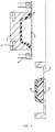
thermal transfer foil 7 does not reach as far as the edges of the moldedarticle 6. - As shown in Fig. 31, in a state where a planar heater 17 (referred to as "side heater" hereinafter) is provided at the side of the molded
article 6, when vacuum extraction is performed, since thethermal transfer foil 7 is partially heated and extended, it is possible to cause thethermal transfer foil 7 to adhere as far as the edges of the moldedarticle 6. - When, in the state described above, the molded
rubber mold 2 is caused to drop, and design thermal transfer is performed, with a conventional method, as shown in Fig. 30, the edges of the molded rubber which are located on the moldedrubber mold 2 collide with thethermal transfer foil 7, thethermal transfer foil 7 is torn, and vacuum breakage results. In addition, since parts of the moldedrubber 3 are heated to 180°C, when collision is with free parts of thethermal transfer foil 7 which is produced using polyethylene terephthalate film, thethermal transfer foil 7 is instantly damaged. - On the other hand, in the state in Fig. 32 at which point the present invention is used, since the
thermal transfer foil 7 is cut so as to adequately drop as far as the lower edges of the molded article, even if the moldedrubber mold 2 is caused to drop, no vacuum breakage occurs, and a favorable design transfer can be performed. A silicon rubber heater was used for theplanar heater 17. - In addition, by applying silicon grease or similar to the surface of the molded
rubber 3, which has parts of a rigid shape, if the coefficient of friction between the surface of the moldedrubber 3 and thethermal transfer foil 7 is small, a more favorable design transfer can be performed. - Therefore, by means of a method employing the present invention, favorable results were obtained when decoration with a wood grain pattern was performed with respect to an air conditioner grill of the shape shown in Figs. 13 to 16.
- Next, a description will be provided with reference to an Example in which the invention and the second solution are employed jointly.
- The molded article is an air conditioner grill possessing the shape shown in Figs. 17 to 20. The dimensions of this molded article are: length 800 mm, width 270 mm,
height 115 mm, and wall faceheight 30 mm. As shown in Fig. 86, when the molded article has a shape in which the side wall angle α is extremely small, even if thethermal transfer foil 7 is extended partially using theplanar heater 17 such that same is attached to the edges of the moldedarticle 6, ring-shaped cuts like those in Fig. 23 caused by contraction of thethermal transfer foil 7 following thermal transfer decoration no longer remain. - A cross-section through the center of the molded article is shown in Fig. 33 as an Example of the second solution. The
thermal transfer foil 7 adheres to the moldedarticle 6 as a result of vacuum extraction. The moldedrubber mold 3 is caused to drop, and, when the moldedrubber 3 is on the verge of reaching the surface of the moldedarticle 6, the blade edge of theshape cutter 19 makes contact with and cuts thethermal transfer foil 7. Immediately thereafter, the moldedrubber 3 reaches the surface of the moldedarticle 6, and the design of thethermal transfer foil 7 is transferred. To describe this in more detail, before cutting, thethermal transfer foil 7 is caused to adhere to the moldedarticle 6 in a state in which there are no wrinkles on same, and since, immediately after cutting, the design is transferred to the molded article by the moldedrubber 3 before wrinkles are produced, wrinkles are not observed on the moldedarticle 6 thus decorated. Moreover, when the moldedrubber mold 2 is raised, as shown in Fig. 35, since thethermal transfer foil 7 is cut, no ring-shaped cuts due to contraction of thethermal transfer foil 7 which has been forcibly extended were produced on the sides of the molded article. Incidentally, since the thermal transfer foil is cut in this method, a winding method cannot be employed. - Therefore, using the method which uses the invention and the second solution, favorable effects were obtained upon performing decoration with a wood grain design, with respect to an air conditioner grill of the shape shown in Figs. 13 to 16.
Claims (1)
- A technique that performs decoration by causing a thermal transfer foil to cover a surface of a large plastic molded article (6) having a three-dimensional shape; clamping the perimeter of the thermal transfer foil (7); attaching the foil to the molded article shape by means of vacuum degassing; and thereafter lowering and raising a molded rubber mold (2), including a method for enabling the decoration of the molded article of a deeper shape by arranging a planar heater (17) at the perimeter of a support jig, and partially heating the thermal transfer foil (7) using the planar heater (17) so as to extend same.
Applications Claiming Priority (1)
| Application Number | Priority Date | Filing Date | Title |
|---|---|---|---|
| PCT/EP2002/005408 WO2003095237A1 (en) | 2002-05-08 | 2002-05-08 | Method of decorating large plastic 3d objects |
Publications (2)
| Publication Number | Publication Date |
|---|---|
| EP1501690A1 EP1501690A1 (en) | 2005-02-02 |
| EP1501690B1 true EP1501690B1 (en) | 2007-11-21 |
Family
ID=29414650
Family Applications (1)
| Application Number | Title | Priority Date | Filing Date |
|---|---|---|---|
| EP02758198A Expired - Lifetime EP1501690B1 (en) | 2002-05-08 | 2002-05-08 | Method of decorating large plastic 3d objects |
Country Status (7)
| Country | Link |
|---|---|
| US (1) | US7504061B2 (en) |
| EP (1) | EP1501690B1 (en) |
| JP (1) | JP4163681B2 (en) |
| CN (1) | CN1278874C (en) |
| AU (1) | AU2002325215A1 (en) |
| DE (1) | DE60223726T2 (en) |
| WO (1) | WO2003095237A1 (en) |
Cited By (2)
| Publication number | Priority date | Publication date | Assignee | Title |
|---|---|---|---|---|
| CN106794606A (en) * | 2014-10-10 | 2017-05-31 | 阿博格有限公司 | Method for further processing prefabricated products and related prefabricated products |
| US9699899B2 (en) | 2011-07-29 | 2017-07-04 | Polyic Gmbh & Co. Kg | Plastic film having lines for a multi-modal input device and method for producing |
Families Citing this family (10)
| Publication number | Priority date | Publication date | Assignee | Title |
|---|---|---|---|---|
| KR100993925B1 (en) * | 2008-03-14 | 2010-11-11 | 포항공과대학교 산학협력단 | Manufacturing method of three-dimensional shaped structure with hydrophobic surface using metal foil |
| KR101512214B1 (en) | 2008-03-25 | 2015-04-14 | 쓰리엠 이노베이티브 프로퍼티즈 컴파니 | Multilayer articles and methods of making and using the same |
| JP5324642B2 (en) | 2008-03-25 | 2013-10-23 | スリーエム イノベイティブ プロパティズ カンパニー | Paint film composite and method for producing the same |
| KR100921062B1 (en) | 2008-05-21 | 2009-10-08 | 현대자동차주식회사 | Lift device in active hood system |
| JP5690560B2 (en) * | 2010-11-19 | 2015-03-25 | 株式会社ファルテック | Hot stamp method |
| DE102012109315A1 (en) | 2012-10-01 | 2014-04-03 | Leonhard Kurz Stiftung & Co. Kg | Method and device for embossing a non-planar surface of a body with a transfer layer of a hot stamping foil |
| JP5799934B2 (en) | 2012-11-09 | 2015-10-28 | 豊田合成株式会社 | Design member manufacturing method and three-dimensional transfer jig |
| KR101450478B1 (en) * | 2013-11-25 | 2014-10-13 | 주식회사 윌리언스 | System for film transferring process |
| KR102117170B1 (en) * | 2018-12-26 | 2020-05-29 | 이용근 | Method of transferring surface of polyester sound absorption board |
| TWI709926B (en) * | 2019-08-27 | 2020-11-11 | 中傳企業股份有限公司 | Dispatch system for mold manufacturing and dispatch method |
Family Cites Families (110)
| Publication number | Priority date | Publication date | Assignee | Title |
|---|---|---|---|---|
| US3493640A (en) * | 1967-01-06 | 1970-02-03 | Owens Illinois Inc | Application of plastic ends to container bodies |
| AU432371B2 (en) * | 1967-07-13 | 1973-02-06 | Commonwealth Scientific And Industrial Research Organization | Plasma sintering |
| US3731047A (en) * | 1971-12-06 | 1973-05-01 | Mc Donnell Douglas Corp | Plasma heating torch |
| US4004934A (en) * | 1973-10-24 | 1977-01-25 | General Electric Company | Sintered dense silicon carbide |
| JPS5823349B2 (en) * | 1975-08-11 | 1983-05-14 | 新日本製鐵株式会社 | Tai Kabutunoshiyouketsuhouhou |
| JPS5378170A (en) * | 1976-12-22 | 1978-07-11 | Toshiba Corp | Continuous processor for gas plasma etching |
| US4025818A (en) * | 1976-04-20 | 1977-05-24 | Hughes Aircraft Company | Wire ion plasma electron gun |
| CA1080562A (en) * | 1977-02-10 | 1980-07-01 | Frederick D. King | Method of and apparatus for manufacturing an optical fibre with plasma activated deposition in a tube |
| JPS55131175A (en) * | 1979-03-30 | 1980-10-11 | Toshiba Corp | Surface treatment apparatus with microwave plasma |
| US4500564A (en) * | 1982-02-01 | 1985-02-19 | Agency Of Industrial Science & Technology | Method for surface treatment by ion bombardment |
| US4504007A (en) * | 1982-09-14 | 1985-03-12 | International Business Machines Corporation | Solder and braze fluxes and processes for using the same |
| US4687680A (en) * | 1983-12-28 | 1987-08-18 | Oike Industrial Co., Ltd. | Stamping foil |
| US4666775A (en) * | 1985-04-01 | 1987-05-19 | Kennecott Corporation | Process for sintering extruded powder shapes |
| US4838973A (en) * | 1986-07-02 | 1989-06-13 | General Motors Corporation | Method of applying painted carrier films to automobile body parts |
| JPH0689456B2 (en) * | 1986-10-01 | 1994-11-09 | キヤノン株式会社 | Functional deposited film forming apparatus by microwave plasma CVD method |
| US4919077A (en) * | 1986-12-27 | 1990-04-24 | Mitsubishi Denki Kabushiki Kaisha | Semiconductor producing apparatus |
| JPH0754759B2 (en) * | 1987-04-27 | 1995-06-07 | 日本電信電話株式会社 | Plasma processing method and apparatus, and mode converter for plasma processing apparatus |
| FR2616614B1 (en) * | 1987-06-10 | 1989-10-20 | Air Liquide | MICROWAVE PLASMA TORCH, DEVICE COMPRISING SUCH A TORCH AND METHOD FOR MANUFACTURING POWDER USING THE SAME |
| US4891488A (en) * | 1987-07-16 | 1990-01-02 | Texas Instruments Incorporated | Processing apparatus and method |
| EP0329338A3 (en) * | 1988-02-16 | 1990-08-01 | Alcan International Limited | Process and apparatus for heating bodies at high temperature and pressure utilizing microwave energy |
| JP2805009B2 (en) * | 1988-05-11 | 1998-09-30 | 株式会社日立製作所 | Plasma generator and plasma element analyzer |
| DE3830249A1 (en) * | 1988-09-06 | 1990-03-15 | Schott Glaswerke | PLASMA PROCESS FOR COATING LEVEL SUBSTRATES |
| US5122431A (en) * | 1988-09-14 | 1992-06-16 | Fujitsu Limited | Thin film formation apparatus |
| US5103715A (en) * | 1989-03-17 | 1992-04-14 | Techco Corporation | Power steering system |
| DE3912568A1 (en) * | 1989-04-17 | 1990-10-18 | Siemens Ag | GAS LASER, ESPECIALLY CO (DOWN ARROW) 2 (DOWN ARROW) LASER |
| EP0476004B1 (en) * | 1989-06-07 | 1993-05-26 | MOSHAMMER, Wolfgang, Dipl.-Ing. | Process and device for irradiating material containing or mixed with water with microwave energy |
| US5114770A (en) * | 1989-06-28 | 1992-05-19 | Canon Kabushiki Kaisha | Method for continuously forming functional deposited films with a large area by a microwave plasma cvd method |
| EP0406690B1 (en) * | 1989-06-28 | 1997-03-12 | Canon Kabushiki Kaisha | Process for continuously forming a large area functional deposited film by microwave PCVD method and an apparatus suitable for practicing the same |
| US5130170A (en) * | 1989-06-28 | 1992-07-14 | Canon Kabushiki Kaisha | Microwave pcvd method for continuously forming a large area functional deposited film using a curved moving substrate web with microwave energy with a directivity in one direction perpendicular to the direction of microwave propagation |
| US5037666A (en) * | 1989-08-03 | 1991-08-06 | Uha Mikakuto Precision Engineering Research Institute Co., Ltd. | High-speed film forming method by microwave plasma chemical vapor deposition (CVD) under high pressure |
| US5125994A (en) * | 1989-11-01 | 1992-06-30 | Eastman Kodak Company | Thermoforming method |
| US5277773A (en) * | 1989-12-27 | 1994-01-11 | Exxon Research & Engineering Co. | Conversion of hydrocarbons using microwave radiation |
| US5023056A (en) * | 1989-12-27 | 1991-06-11 | The United States Of America As Represented By The Secretary Of The Navy | Plasma generator utilizing dielectric member for carrying microwave energy |
| KR910016054A (en) * | 1990-02-23 | 1991-09-30 | 미다 가쓰시게 | Surface Treatment Apparatus and Method for Microelectronic Devices |
| US5120567A (en) * | 1990-05-17 | 1992-06-09 | General Electric Company | Low frequency plasma spray method in which a stable plasma is created by operating a spray gun at less than 1 mhz in a mixture of argon and helium gas |
| US5307892A (en) * | 1990-08-03 | 1994-05-03 | Techco Corporation | Electronically controlled power steering system |
| US5085885A (en) * | 1990-09-10 | 1992-02-04 | University Of Delaware | Plasma-induced, in-situ generation, transport and use or collection of reactive precursors |
| DE4029270C1 (en) * | 1990-09-14 | 1992-04-09 | Balzers Ag, Balzers, Li | |
| JP2958086B2 (en) * | 1990-09-18 | 1999-10-06 | 奈良精機株式会社 | Melting device for injection needle |
| US5087272A (en) * | 1990-10-17 | 1992-02-11 | Nixdorf Richard D | Filter and means for regeneration thereof |
| JP2714247B2 (en) * | 1990-10-29 | 1998-02-16 | キヤノン株式会社 | Method and apparatus for continuously forming large-area functional deposited film by microwave plasma CVD |
| JP2824808B2 (en) * | 1990-11-16 | 1998-11-18 | キヤノン株式会社 | Apparatus for continuously forming large-area functional deposited films by microwave plasma CVD |
| AU649770B2 (en) * | 1991-01-25 | 1994-06-02 | Societe Prolabo | Apparatus for simultaneous treatment, in a moist medium, on a plurality of samples, and utilisation of the said apparatus |
| US5202541A (en) * | 1991-01-28 | 1993-04-13 | Alcan International Limited | Microwave heating of workpieces |
| EP0502269A1 (en) * | 1991-03-06 | 1992-09-09 | Hitachi, Ltd. | Method of and system for microwave plasma treatments |
| US5223308A (en) * | 1991-10-18 | 1993-06-29 | Energy Conversion Devices, Inc. | Low temperature plasma enhanced CVD process within tubular members |
| US5321223A (en) * | 1991-10-23 | 1994-06-14 | Martin Marietta Energy Systems, Inc. | Method of sintering materials with microwave radiation |
| US5521360A (en) * | 1994-09-14 | 1996-05-28 | Martin Marietta Energy Systems, Inc. | Apparatus and method for microwave processing of materials |
| US5311906A (en) * | 1992-02-04 | 1994-05-17 | Techco Corporation | Preload mechanism for power steering apparatus |
| US5316043A (en) * | 1992-02-04 | 1994-05-31 | Techco Corporation | Preload mechanism for power steering apparatus |
| US5525290A (en) * | 1992-04-09 | 1996-06-11 | Wes Carpenter | Method of manufacturing a decorated helmet |
| US5318660A (en) | 1992-05-01 | 1994-06-07 | Kensol-Olsenmark, Inc. | Method and apparatus for generating hot stamped single and multi-color images |
| US5330800A (en) * | 1992-11-04 | 1994-07-19 | Hughes Aircraft Company | High impedance plasma ion implantation method and apparatus |
| JP2738251B2 (en) * | 1993-01-20 | 1998-04-08 | 松下電器産業株式会社 | Filter regeneration device for internal combustion engine |
| JP3365511B2 (en) * | 1993-04-05 | 2003-01-14 | セイコーエプソン株式会社 | Method and apparatus for joining with brazing material |
| US5401355A (en) | 1993-05-11 | 1995-03-28 | Stiller; Larry B. | Apparatus for manufacturing multiple colored pliable soft trim components using movable dies |
| JP2803017B2 (en) * | 1993-06-07 | 1998-09-24 | 工業技術院長 | Antithrombotic medical material and medical device, and their manufacturing method, manufacturing apparatus, and plasma processing apparatus |
| JP2772241B2 (en) | 1993-06-23 | 1998-07-02 | 国城金型工業株式会社 | Thermal transfer device |
| US5755097A (en) * | 1993-07-29 | 1998-05-26 | Techco Corporation | Bootstrap power steering systems |
| US5505275A (en) * | 1993-09-09 | 1996-04-09 | Techo Corporation | Power steering system |
| US6342195B1 (en) * | 1993-10-01 | 2002-01-29 | The Penn State Research Foundation | Method for synthesizing solids such as diamond and products produced thereby |
| GB9414561D0 (en) * | 1994-07-19 | 1994-09-07 | Ea Tech Ltd | Method of and apparatus for microwave-plasma production |
| JPH0891951A (en) * | 1994-09-22 | 1996-04-09 | Sumitomo Electric Ind Ltd | Aluminum-silicon nitride bonded body and method for producing the same |
| IT1277343B1 (en) | 1995-07-25 | 1997-11-10 | Wintune Graphics Inc | PROCEDURE FOR THE APPLICATION OF A FINISHING SHEET TO A SUBSTRATE PARTICULARLY BODY PARTS OF MOPEDS |
| US5712000A (en) * | 1995-10-12 | 1998-01-27 | Hughes Aircraft Company | Large-scale, low pressure plasma-ion deposition of diamondlike carbon films |
| US5859404A (en) * | 1995-10-12 | 1999-01-12 | Hughes Electronics Corporation | Method and apparatus for plasma processing a workpiece in an enveloping plasma |
| JP3895000B2 (en) * | 1996-06-06 | 2007-03-22 | Dowaホールディングス株式会社 | Carburizing, quenching and tempering method and apparatus |
| JPH1081971A (en) * | 1996-07-10 | 1998-03-31 | Suzuki Motor Corp | Method and apparatus for forming SiC thin film on polymer substrate by plasma CVD |
| GB2315038A (en) | 1996-07-10 | 1998-01-21 | Jpe Canada Inc | Process and apparatus for the manufacture of film-coated moulded pieces |
| US6011248A (en) * | 1996-07-26 | 2000-01-04 | Dennis; Mahlon Denton | Method and apparatus for fabrication and sintering composite inserts |
| US6038854A (en) * | 1996-08-19 | 2000-03-21 | The Regents Of The University Of California | Plasma regenerated particulate trap and NOx reduction system |
| US6248206B1 (en) * | 1996-10-01 | 2001-06-19 | Applied Materials Inc. | Apparatus for sidewall profile control during an etch process |
| US5734501A (en) * | 1996-11-01 | 1998-03-31 | Minnesota Mining And Manufacturing Company | Highly canted retroreflective cube corner article |
| US5715677A (en) * | 1996-11-13 | 1998-02-10 | The Regents Of The University Of California | Diesel NOx reduction by plasma-regenerated absorbend beds |
| WO1998032312A1 (en) * | 1997-01-17 | 1998-07-23 | California Institute Of Technology | Microwave technique for brazing materials |
| US6189482B1 (en) * | 1997-02-12 | 2001-02-20 | Applied Materials, Inc. | High temperature, high flow rate chemical vapor deposition apparatus and related methods |
| US6054700A (en) * | 1997-04-10 | 2000-04-25 | Nucon Systems | Process and apparatus for joining thick-walled ceramic parts |
| FR2762748B1 (en) * | 1997-04-25 | 1999-06-11 | Air Liquide | SURFACE WAVE PLASMA GAS EXCITATION DEVICE |
| JPH1154773A (en) * | 1997-08-01 | 1999-02-26 | Canon Inc | Photovoltaic element and method for manufacturing the same |
| US6183689B1 (en) * | 1997-11-25 | 2001-02-06 | Penn State Research Foundation | Process for sintering powder metal components |
| US6028393A (en) * | 1998-01-22 | 2000-02-22 | Energy Conversion Devices, Inc. | E-beam/microwave gas jet PECVD method and apparatus for depositing and/or surface modification of thin film materials |
| US20020034461A1 (en) * | 1998-01-29 | 2002-03-21 | Segal David Leslie | Plasma assisted processing of gas |
| DE19814812C2 (en) * | 1998-04-02 | 2000-05-11 | Mut Mikrowellen Umwelt Technol | Plasma torch with a microwave transmitter |
| US6228773B1 (en) * | 1998-04-14 | 2001-05-08 | Matrix Integrated Systems, Inc. | Synchronous multiplexed near zero overhead architecture for vacuum processes |
| JP4037956B2 (en) * | 1998-04-28 | 2008-01-23 | 東海カーボン株式会社 | Chamber inner wall protection member |
| US6280823B1 (en) * | 1998-05-22 | 2001-08-28 | Patent Holding Company | Foil-covered plastic part and method of making same |
| JP4014300B2 (en) * | 1998-06-19 | 2007-11-28 | 東京エレクトロン株式会社 | Plasma processing equipment |
| JP2000021871A (en) * | 1998-06-30 | 2000-01-21 | Tokyo Electron Ltd | Plasma processing method |
| GB2345661A (en) | 1998-07-13 | 2000-07-19 | Robobond Ltd | Decorating ornamented articles |
| CA2338230A1 (en) * | 1998-07-21 | 2000-02-03 | Edward H. Phillips | Feedback and servo control for electric power steering systems |
| JP2991192B1 (en) * | 1998-07-23 | 1999-12-20 | 日本電気株式会社 | Plasma processing method and plasma processing apparatus |
| US6362449B1 (en) * | 1998-08-12 | 2002-03-26 | Massachusetts Institute Of Technology | Very high power microwave-induced plasma |
| KR100634655B1 (en) | 1998-10-01 | 2006-10-16 | 니폰샤신인사츠가부시키가이샤 | Transfer material, surface protective sheet, and manufacturing method of the molded article using these |
| US6204606B1 (en) * | 1998-10-01 | 2001-03-20 | The University Of Tennessee Research Corporation | Slotted waveguide structure for generating plasma discharges |
| US6186090B1 (en) * | 1999-03-04 | 2001-02-13 | Energy Conversion Devices, Inc. | Apparatus for the simultaneous deposition by physical vapor deposition and chemical vapor deposition and method therefor |
| SE516722C2 (en) * | 1999-04-28 | 2002-02-19 | Hana Barankova | Process and apparatus for plasma gas treatment |
| FR2797372B1 (en) * | 1999-08-04 | 2002-10-25 | Metal Process | METHOD FOR PRODUCING ELEMENTARY PLASMAS WITH A VIEW TO CREATING A UNIFORM PLASMA FOR A USING SURFACE AND DEVICE FOR PRODUCING SUCH A PLASMA |
| US6365885B1 (en) * | 1999-10-18 | 2002-04-02 | The Penn State Research Foundation | Microwave processing in pure H fields and pure E fields |
| JP3595233B2 (en) * | 2000-02-16 | 2004-12-02 | 株式会社ノリタケカンパニーリミテド | Electron emission source and method of manufacturing the same |
| US6367412B1 (en) * | 2000-02-17 | 2002-04-09 | Applied Materials, Inc. | Porous ceramic liner for a plasma source |
| DE10009569C2 (en) * | 2000-02-29 | 2003-03-27 | Schott Glas | Method and device for comminuting glass bodies by means of microwave heating |
| US6345497B1 (en) * | 2000-03-02 | 2002-02-12 | The Regents Of The University Of California | NOx reduction by electron beam-produced nitrogen atom injection |
| KR100341407B1 (en) * | 2000-05-01 | 2002-06-22 | 윤덕용 | A Crystall ization method of lithium transition metal oxide thin films by plasma treatm ent |
| JP4523118B2 (en) * | 2000-06-14 | 2010-08-11 | 東京エレクトロン株式会社 | Plasma processing equipment |
| JP3865289B2 (en) * | 2000-11-22 | 2007-01-10 | 独立行政法人科学技術振興機構 | Microwave plasma generator |
| AU2002237870A1 (en) * | 2001-01-17 | 2002-07-30 | The Penn State Research Foundation | Microwave processing using highly microwave absorbing powdered material layers |
| JP2002280196A (en) * | 2001-03-15 | 2002-09-27 | Micro Denshi Kk | Plasma generating device using microwave |
| JP2003075077A (en) * | 2001-09-05 | 2003-03-12 | Natl Inst For Fusion Science | Microwave firing furnace and microwave firing method |
| AU2003234476A1 (en) * | 2002-05-08 | 2003-11-11 | Dana Corporation | Plasma-assisted nitrogen surface-treatment |
| US7097782B2 (en) * | 2002-11-12 | 2006-08-29 | Micron Technology, Inc. | Method of exposing a substrate to a surface microwave plasma, etching method, deposition method, surface microwave plasma generating apparatus, semiconductor substrate etching apparatus, semiconductor substrate deposition apparatus, and microwave plasma generating antenna assembly |
-
2002
- 2002-05-08 US US10/513,494 patent/US7504061B2/en not_active Expired - Lifetime
- 2002-05-08 CN CNB028288971A patent/CN1278874C/en not_active Expired - Fee Related
- 2002-05-08 DE DE60223726T patent/DE60223726T2/en not_active Expired - Lifetime
- 2002-05-08 JP JP2004503289A patent/JP4163681B2/en not_active Expired - Fee Related
- 2002-05-08 WO PCT/EP2002/005408 patent/WO2003095237A1/en not_active Ceased
- 2002-05-08 EP EP02758198A patent/EP1501690B1/en not_active Expired - Lifetime
- 2002-05-08 AU AU2002325215A patent/AU2002325215A1/en not_active Abandoned
Cited By (3)
| Publication number | Priority date | Publication date | Assignee | Title |
|---|---|---|---|---|
| US9699899B2 (en) | 2011-07-29 | 2017-07-04 | Polyic Gmbh & Co. Kg | Plastic film having lines for a multi-modal input device and method for producing |
| CN106794606A (en) * | 2014-10-10 | 2017-05-31 | 阿博格有限公司 | Method for further processing prefabricated products and related prefabricated products |
| CN106794606B (en) * | 2014-10-10 | 2019-11-19 | 阿博格有限公司 | Method for further processing prefabricated products and related prefabricated products |
Also Published As
| Publication number | Publication date |
|---|---|
| JP2005524557A (en) | 2005-08-18 |
| DE60223726D1 (en) | 2008-01-03 |
| CN1278874C (en) | 2006-10-11 |
| CN1625489A (en) | 2005-06-08 |
| JP4163681B2 (en) | 2008-10-08 |
| EP1501690A1 (en) | 2005-02-02 |
| US7504061B2 (en) | 2009-03-17 |
| US20060231983A1 (en) | 2006-10-19 |
| WO2003095237A1 (en) | 2003-11-20 |
| DE60223726T2 (en) | 2008-10-30 |
| AU2002325215A1 (en) | 2003-11-11 |
Similar Documents
| Publication | Publication Date | Title |
|---|---|---|
| US5641372A (en) | Transferring apparatus and transferring method | |
| US7504061B2 (en) | Method of decorating large plastic 3D objects | |
| EP2010337B1 (en) | Paint tray and method of manufacture | |
| JP5580445B2 (en) | A card that incorporates visible valuable items | |
| WO2005009668A9 (en) | Method for making a thin die to be used in a press | |
| US5429700A (en) | Waterproof art | |
| US3279144A (en) | Method of partially encapsulating and mounting merchandise for display | |
| IT9021836A1 (en) | METHOD FOR MAKING A CONTINUOUS SHEET OF LABELS. | |
| EP3597714A1 (en) | Restickable lettering film and manufacturing method thereof | |
| EP2114296B1 (en) | Singular id process and product | |
| US3380583A (en) | Package | |
| JP2578554B2 (en) | Method of manufacturing a steering wheel for automobiles with a veneer pattern | |
| JP4378539B2 (en) | A method of attaching an adhesive to a thin-walled part and a jig used therefor. | |
| JPH0592546A (en) | Transfer device | |
| JP2011194686A (en) | Molded article with decorative surface | |
| JP2002166700A (en) | Decorating method for three-dimensional shape made of large-sized plastic | |
| JPS61220822A (en) | Manufacture of formed body bonded partially with skin member | |
| JP2016087960A (en) | Production method of film-decorated component and film-decorated component | |
| JP3579987B2 (en) | Method of manufacturing insulator for case | |
| KR100824804B1 (en) | How to make a label | |
| JPH0340720B2 (en) | ||
| JPH0692118B2 (en) | Method of applying skin material to molded interior base material | |
| JPH10119073A (en) | Molding method of laminated molded body | |
| JPH03223784A (en) | Manufacture of label | |
| JPH0592547A (en) | Transfer device |
Legal Events
| Date | Code | Title | Description |
|---|---|---|---|
| PUAI | Public reference made under article 153(3) epc to a published international application that has entered the european phase |
Free format text: ORIGINAL CODE: 0009012 |
|
| 17P | Request for examination filed |
Effective date: 20041019 |
|
| AK | Designated contracting states |
Kind code of ref document: A1 Designated state(s): AT BE CH CY DE DK ES FI FR GB GR IE IT LI LU MC NL PT SE TR |
|
| AX | Request for extension of the european patent |
Extension state: AL LT LV MK RO SI |
|
| DAX | Request for extension of the european patent (deleted) | ||
| GRAP | Despatch of communication of intention to grant a patent |
Free format text: ORIGINAL CODE: EPIDOSNIGR1 |
|
| GRAS | Grant fee paid |
Free format text: ORIGINAL CODE: EPIDOSNIGR3 |
|
| RAP1 | Party data changed (applicant data changed or rights of an application transferred) |
Owner name: LEONHARD KURZ GMBH & CO. KG |
|
| GRAA | (expected) grant |
Free format text: ORIGINAL CODE: 0009210 |
|
| AK | Designated contracting states |
Kind code of ref document: B1 Designated state(s): AT BE CH CY DE DK ES FI FR GB GR IE IT LI LU MC NL PT SE TR |
|
| REG | Reference to a national code |
Ref country code: GB Ref legal event code: FG4D |
|
| REG | Reference to a national code |
Ref country code: IE Ref legal event code: FG4D |
|
| REG | Reference to a national code |
Ref country code: CH Ref legal event code: EP |
|
| RAP2 | Party data changed (patent owner data changed or rights of a patent transferred) |
Owner name: LEONHARD KURZ STIFTUNG & CO. KG |
|
| REF | Corresponds to: |
Ref document number: 60223726 Country of ref document: DE Date of ref document: 20080103 Kind code of ref document: P |
|
| NLT2 | Nl: modifications (of names), taken from the european patent patent bulletin |
Owner name: LEONHARD KURZ STIFTUNG & CO. KG Effective date: 20071226 |
|
| PG25 | Lapsed in a contracting state [announced via postgrant information from national office to epo] |
Ref country code: ES Free format text: LAPSE BECAUSE OF FAILURE TO SUBMIT A TRANSLATION OF THE DESCRIPTION OR TO PAY THE FEE WITHIN THE PRESCRIBED TIME-LIMIT Effective date: 20080304 Ref country code: NL Free format text: LAPSE BECAUSE OF FAILURE TO SUBMIT A TRANSLATION OF THE DESCRIPTION OR TO PAY THE FEE WITHIN THE PRESCRIBED TIME-LIMIT Effective date: 20071121 Ref country code: SE Free format text: LAPSE BECAUSE OF FAILURE TO SUBMIT A TRANSLATION OF THE DESCRIPTION OR TO PAY THE FEE WITHIN THE PRESCRIBED TIME-LIMIT Effective date: 20080221 Ref country code: CH Free format text: LAPSE BECAUSE OF FAILURE TO SUBMIT A TRANSLATION OF THE DESCRIPTION OR TO PAY THE FEE WITHIN THE PRESCRIBED TIME-LIMIT Effective date: 20071121 Ref country code: LI Free format text: LAPSE BECAUSE OF FAILURE TO SUBMIT A TRANSLATION OF THE DESCRIPTION OR TO PAY THE FEE WITHIN THE PRESCRIBED TIME-LIMIT Effective date: 20071121 |
|
| NLV1 | Nl: lapsed or annulled due to failure to fulfill the requirements of art. 29p and 29m of the patents act | ||
| PG25 | Lapsed in a contracting state [announced via postgrant information from national office to epo] |
Ref country code: FI Free format text: LAPSE BECAUSE OF FAILURE TO SUBMIT A TRANSLATION OF THE DESCRIPTION OR TO PAY THE FEE WITHIN THE PRESCRIBED TIME-LIMIT Effective date: 20071121 |
|
| REG | Reference to a national code |
Ref country code: CH Ref legal event code: PL |
|
| PG25 | Lapsed in a contracting state [announced via postgrant information from national office to epo] |
Ref country code: AT Free format text: LAPSE BECAUSE OF FAILURE TO SUBMIT A TRANSLATION OF THE DESCRIPTION OR TO PAY THE FEE WITHIN THE PRESCRIBED TIME-LIMIT Effective date: 20071121 |
|
| ET | Fr: translation filed | ||
| PG25 | Lapsed in a contracting state [announced via postgrant information from national office to epo] |
Ref country code: DK Free format text: LAPSE BECAUSE OF FAILURE TO SUBMIT A TRANSLATION OF THE DESCRIPTION OR TO PAY THE FEE WITHIN THE PRESCRIBED TIME-LIMIT Effective date: 20071121 |
|
| PG25 | Lapsed in a contracting state [announced via postgrant information from national office to epo] |
Ref country code: BE Free format text: LAPSE BECAUSE OF FAILURE TO SUBMIT A TRANSLATION OF THE DESCRIPTION OR TO PAY THE FEE WITHIN THE PRESCRIBED TIME-LIMIT Effective date: 20071121 |
|
| PLBE | No opposition filed within time limit |
Free format text: ORIGINAL CODE: 0009261 |
|
| STAA | Information on the status of an ep patent application or granted ep patent |
Free format text: STATUS: NO OPPOSITION FILED WITHIN TIME LIMIT |
|
| PG25 | Lapsed in a contracting state [announced via postgrant information from national office to epo] |
Ref country code: PT Free format text: LAPSE BECAUSE OF FAILURE TO SUBMIT A TRANSLATION OF THE DESCRIPTION OR TO PAY THE FEE WITHIN THE PRESCRIBED TIME-LIMIT Effective date: 20080421 |
|
| 26N | No opposition filed |
Effective date: 20080822 |
|
| PG25 | Lapsed in a contracting state [announced via postgrant information from national office to epo] |
Ref country code: MC Free format text: LAPSE BECAUSE OF NON-PAYMENT OF DUE FEES Effective date: 20080531 |
|
| PG25 | Lapsed in a contracting state [announced via postgrant information from national office to epo] |
Ref country code: GR Free format text: LAPSE BECAUSE OF FAILURE TO SUBMIT A TRANSLATION OF THE DESCRIPTION OR TO PAY THE FEE WITHIN THE PRESCRIBED TIME-LIMIT Effective date: 20080222 |
|
| PG25 | Lapsed in a contracting state [announced via postgrant information from national office to epo] |
Ref country code: IE Free format text: LAPSE BECAUSE OF NON-PAYMENT OF DUE FEES Effective date: 20080508 |
|
| PG25 | Lapsed in a contracting state [announced via postgrant information from national office to epo] |
Ref country code: CY Free format text: LAPSE BECAUSE OF FAILURE TO SUBMIT A TRANSLATION OF THE DESCRIPTION OR TO PAY THE FEE WITHIN THE PRESCRIBED TIME-LIMIT Effective date: 20071121 |
|
| PG25 | Lapsed in a contracting state [announced via postgrant information from national office to epo] |
Ref country code: LU Free format text: LAPSE BECAUSE OF NON-PAYMENT OF DUE FEES Effective date: 20080508 |
|
| PG25 | Lapsed in a contracting state [announced via postgrant information from national office to epo] |
Ref country code: TR Free format text: LAPSE BECAUSE OF FAILURE TO SUBMIT A TRANSLATION OF THE DESCRIPTION OR TO PAY THE FEE WITHIN THE PRESCRIBED TIME-LIMIT Effective date: 20071121 |
|
| REG | Reference to a national code |
Ref country code: FR Ref legal event code: PLFP Year of fee payment: 15 |
|
| REG | Reference to a national code |
Ref country code: FR Ref legal event code: PLFP Year of fee payment: 16 |
|
| REG | Reference to a national code |
Ref country code: FR Ref legal event code: PLFP Year of fee payment: 17 |
|
| PGFP | Annual fee paid to national office [announced via postgrant information from national office to epo] |
Ref country code: DE Payment date: 20200526 Year of fee payment: 19 Ref country code: FR Payment date: 20200519 Year of fee payment: 19 |
|
| PGFP | Annual fee paid to national office [announced via postgrant information from national office to epo] |
Ref country code: IT Payment date: 20200528 Year of fee payment: 19 Ref country code: GB Payment date: 20200522 Year of fee payment: 19 |
|
| REG | Reference to a national code |
Ref country code: DE Ref legal event code: R119 Ref document number: 60223726 Country of ref document: DE |
|
| GBPC | Gb: european patent ceased through non-payment of renewal fee |
Effective date: 20210508 |
|
| PG25 | Lapsed in a contracting state [announced via postgrant information from national office to epo] |
Ref country code: GB Free format text: LAPSE BECAUSE OF NON-PAYMENT OF DUE FEES Effective date: 20210508 Ref country code: DE Free format text: LAPSE BECAUSE OF NON-PAYMENT OF DUE FEES Effective date: 20211201 |
|
| PG25 | Lapsed in a contracting state [announced via postgrant information from national office to epo] |
Ref country code: FR Free format text: LAPSE BECAUSE OF NON-PAYMENT OF DUE FEES Effective date: 20210531 |
|
| PG25 | Lapsed in a contracting state [announced via postgrant information from national office to epo] |
Ref country code: IT Free format text: LAPSE BECAUSE OF NON-PAYMENT OF DUE FEES Effective date: 20200508 |
|
| PG25 | Lapsed in a contracting state [announced via postgrant information from national office to epo] |
Ref country code: IT Free format text: LAPSE BECAUSE OF NON-PAYMENT OF DUE FEES Effective date: 20210508 |