EP1501419B1 - Mit kontrastmittel verstärkte farbliche darstellung von strömungen - Google Patents
Mit kontrastmittel verstärkte farbliche darstellung von strömungen Download PDFInfo
- Publication number
- EP1501419B1 EP1501419B1 EP03710155A EP03710155A EP1501419B1 EP 1501419 B1 EP1501419 B1 EP 1501419B1 EP 03710155 A EP03710155 A EP 03710155A EP 03710155 A EP03710155 A EP 03710155A EP 1501419 B1 EP1501419 B1 EP 1501419B1
- Authority
- EP
- European Patent Office
- Prior art keywords
- tissue
- contrast
- ultrasonic
- color
- generated
- Prior art date
- Legal status (The legal status is an assumption and is not a legal conclusion. Google has not performed a legal analysis and makes no representation as to the accuracy of the status listed.)
- Expired - Lifetime
Links
- 239000002872 contrast media Substances 0.000 title claims abstract description 94
- 238000003384 imaging method Methods 0.000 title claims abstract description 65
- 238000000034 method Methods 0.000 claims abstract description 78
- 238000012545 processing Methods 0.000 claims abstract description 45
- 238000002592 echocardiography Methods 0.000 claims abstract description 30
- 230000033001 locomotion Effects 0.000 claims abstract description 26
- 230000004044 response Effects 0.000 claims description 62
- 238000002604 ultrasonography Methods 0.000 claims description 24
- 238000012285 ultrasound imaging Methods 0.000 claims description 23
- 238000010304 firing Methods 0.000 claims description 6
- 210000004204 blood vessel Anatomy 0.000 abstract description 7
- 210000001519 tissue Anatomy 0.000 description 88
- 238000010586 diagram Methods 0.000 description 15
- 230000008569 process Effects 0.000 description 14
- 238000005111 flow chemistry technique Methods 0.000 description 12
- 230000006870 function Effects 0.000 description 12
- 238000012937 correction Methods 0.000 description 11
- 239000008280 blood Substances 0.000 description 10
- 230000017531 blood circulation Effects 0.000 description 10
- 210000004369 blood Anatomy 0.000 description 9
- 230000000694 effects Effects 0.000 description 9
- 238000012360 testing method Methods 0.000 description 9
- 230000005284 excitation Effects 0.000 description 8
- 239000000523 sample Substances 0.000 description 8
- 230000008901 benefit Effects 0.000 description 6
- 238000001514 detection method Methods 0.000 description 6
- 238000006243 chemical reaction Methods 0.000 description 5
- 238000004891 communication Methods 0.000 description 5
- 210000003484 anatomy Anatomy 0.000 description 4
- 238000001914 filtration Methods 0.000 description 4
- 230000007246 mechanism Effects 0.000 description 4
- 210000004165 myocardium Anatomy 0.000 description 4
- 230000005540 biological transmission Effects 0.000 description 3
- 239000003795 chemical substances by application Substances 0.000 description 3
- 238000002059 diagnostic imaging Methods 0.000 description 3
- 238000000614 phase inversion technique Methods 0.000 description 3
- 239000011257 shell material Substances 0.000 description 3
- 230000009286 beneficial effect Effects 0.000 description 2
- 210000004027 cell Anatomy 0.000 description 2
- 230000001276 controlling effect Effects 0.000 description 2
- 238000013480 data collection Methods 0.000 description 2
- 238000001990 intravenous administration Methods 0.000 description 2
- 229910052451 lead zirconate titanate Inorganic materials 0.000 description 2
- 239000000463 material Substances 0.000 description 2
- 238000012986 modification Methods 0.000 description 2
- 230000004048 modification Effects 0.000 description 2
- 230000002107 myocardial effect Effects 0.000 description 2
- 230000003287 optical effect Effects 0.000 description 2
- 206010011224 Cough Diseases 0.000 description 1
- 206010028980 Neoplasm Diseases 0.000 description 1
- 108091081062 Repeated sequence (DNA) Proteins 0.000 description 1
- 230000006399 behavior Effects 0.000 description 1
- 230000033228 biological regulation Effects 0.000 description 1
- 210000000601 blood cell Anatomy 0.000 description 1
- 230000008081 blood perfusion Effects 0.000 description 1
- 230000036770 blood supply Effects 0.000 description 1
- 210000000748 cardiovascular system Anatomy 0.000 description 1
- 230000015556 catabolic process Effects 0.000 description 1
- 230000008859 change Effects 0.000 description 1
- 210000000038 chest Anatomy 0.000 description 1
- 239000003086 colorant Substances 0.000 description 1
- 239000002131 composite material Substances 0.000 description 1
- 210000004351 coronary vessel Anatomy 0.000 description 1
- 230000001186 cumulative effect Effects 0.000 description 1
- 238000006731 degradation reaction Methods 0.000 description 1
- 230000001934 delay Effects 0.000 description 1
- 230000003111 delayed effect Effects 0.000 description 1
- 230000001419 dependent effect Effects 0.000 description 1
- 230000001066 destructive effect Effects 0.000 description 1
- 238000007435 diagnostic evaluation Methods 0.000 description 1
- 239000003814 drug Substances 0.000 description 1
- 229940079593 drug Drugs 0.000 description 1
- 238000005516 engineering process Methods 0.000 description 1
- 230000036541 health Effects 0.000 description 1
- 230000000977 initiatory effect Effects 0.000 description 1
- HFGPZNIAWCZYJU-UHFFFAOYSA-N lead zirconate titanate Chemical compound [O-2].[O-2].[O-2].[O-2].[O-2].[Ti+4].[Zr+4].[Pb+2] HFGPZNIAWCZYJU-UHFFFAOYSA-N 0.000 description 1
- 150000002632 lipids Chemical class 0.000 description 1
- 239000004005 microsphere Substances 0.000 description 1
- 239000013307 optical fiber Substances 0.000 description 1
- 210000000056 organ Anatomy 0.000 description 1
- 230000010355 oscillation Effects 0.000 description 1
- 230000010412 perfusion Effects 0.000 description 1
- 238000012805 post-processing Methods 0.000 description 1
- 230000000644 propagated effect Effects 0.000 description 1
- 102000004169 proteins and genes Human genes 0.000 description 1
- 108090000623 proteins and genes Proteins 0.000 description 1
- 230000008707 rearrangement Effects 0.000 description 1
- 238000011084 recovery Methods 0.000 description 1
- 230000009467 reduction Effects 0.000 description 1
- 230000001105 regulatory effect Effects 0.000 description 1
- 230000029058 respiratory gaseous exchange Effects 0.000 description 1
- 238000005070 sampling Methods 0.000 description 1
- 239000004065 semiconductor Substances 0.000 description 1
- 230000035945 sensitivity Effects 0.000 description 1
- 238000000926 separation method Methods 0.000 description 1
- 241000894007 species Species 0.000 description 1
- 230000001629 suppression Effects 0.000 description 1
Images


Classifications
-
- A—HUMAN NECESSITIES
- A61—MEDICAL OR VETERINARY SCIENCE; HYGIENE
- A61B—DIAGNOSIS; SURGERY; IDENTIFICATION
- A61B8/00—Diagnosis using ultrasonic, sonic or infrasonic waves
- A61B8/48—Diagnostic techniques
- A61B8/481—Diagnostic techniques involving the use of contrast agents, e.g. microbubbles introduced into the bloodstream
-
- A—HUMAN NECESSITIES
- A61—MEDICAL OR VETERINARY SCIENCE; HYGIENE
- A61B—DIAGNOSIS; SURGERY; IDENTIFICATION
- A61B8/00—Diagnosis using ultrasonic, sonic or infrasonic waves
- A61B8/06—Measuring blood flow
-
- A—HUMAN NECESSITIES
- A61—MEDICAL OR VETERINARY SCIENCE; HYGIENE
- A61B—DIAGNOSIS; SURGERY; IDENTIFICATION
- A61B8/00—Diagnosis using ultrasonic, sonic or infrasonic waves
- A61B8/13—Tomography
-
- G—PHYSICS
- G01—MEASURING; TESTING
- G01S—RADIO DIRECTION-FINDING; RADIO NAVIGATION; DETERMINING DISTANCE OR VELOCITY BY USE OF RADIO WAVES; LOCATING OR PRESENCE-DETECTING BY USE OF THE REFLECTION OR RERADIATION OF RADIO WAVES; ANALOGOUS ARRANGEMENTS USING OTHER WAVES
- G01S15/00—Systems using the reflection or reradiation of acoustic waves, e.g. sonar systems
- G01S15/02—Systems using the reflection or reradiation of acoustic waves, e.g. sonar systems using reflection of acoustic waves
- G01S15/06—Systems determining the position data of a target
- G01S15/08—Systems for measuring distance only
- G01S15/10—Systems for measuring distance only using transmission of interrupted, pulse-modulated waves
- G01S15/102—Systems for measuring distance only using transmission of interrupted, pulse-modulated waves using transmission of pulses having some particular characteristics
-
- G—PHYSICS
- G01—MEASURING; TESTING
- G01S—RADIO DIRECTION-FINDING; RADIO NAVIGATION; DETERMINING DISTANCE OR VELOCITY BY USE OF RADIO WAVES; LOCATING OR PRESENCE-DETECTING BY USE OF THE REFLECTION OR RERADIATION OF RADIO WAVES; ANALOGOUS ARRANGEMENTS USING OTHER WAVES
- G01S15/00—Systems using the reflection or reradiation of acoustic waves, e.g. sonar systems
- G01S15/88—Sonar systems specially adapted for specific applications
- G01S15/89—Sonar systems specially adapted for specific applications for mapping or imaging
- G01S15/8906—Short-range imaging systems; Acoustic microscope systems using pulse-echo techniques
- G01S15/8979—Combined Doppler and pulse-echo imaging systems
- G01S15/8981—Discriminating between fixed and moving objects or between objects moving at different speeds, e.g. wall clutter filter
-
- G—PHYSICS
- G01—MEASURING; TESTING
- G01S—RADIO DIRECTION-FINDING; RADIO NAVIGATION; DETERMINING DISTANCE OR VELOCITY BY USE OF RADIO WAVES; LOCATING OR PRESENCE-DETECTING BY USE OF THE REFLECTION OR RERADIATION OF RADIO WAVES; ANALOGOUS ARRANGEMENTS USING OTHER WAVES
- G01S7/00—Details of systems according to groups G01S13/00, G01S15/00, G01S17/00
- G01S7/52—Details of systems according to groups G01S13/00, G01S15/00, G01S17/00 of systems according to group G01S15/00
- G01S7/52017—Details of systems according to groups G01S13/00, G01S15/00, G01S17/00 of systems according to group G01S15/00 particularly adapted to short-range imaging
- G01S7/52023—Details of receivers
- G01S7/52036—Details of receivers using analysis of echo signal for target characterisation
- G01S7/52038—Details of receivers using analysis of echo signal for target characterisation involving non-linear properties of the propagation medium or of the reflective target
- G01S7/52039—Details of receivers using analysis of echo signal for target characterisation involving non-linear properties of the propagation medium or of the reflective target exploiting the non-linear response of a contrast enhancer, e.g. a contrast agent
Definitions
- the present disclosure relates to ultrasonic imaging. More particularly, a system and method for improved contrast-agent enhanced-diagnostic evaluations are disclosed.
- Ultrasonic imaging has quickly replaced conventional X-rays in many clinical applications because of its image quality, safety, and low cost.
- Ultrasonic images are typically formed through the use of phased or linear-array transducers which are capable of transmitting and receiving pressure waves directed into a medium such as the human body. These ultrasonic transducers may be further assembled into a housing, which may contain control electronics, the combination of which forms an ultrasonic probe. Ultrasonic probes are used along with an ultrasonic transceiver to transmit and receive pressure waves through the various tissues of the body. The various ultrasonic responses are then processed by an ultrasonic-imaging system to display the various structures and tissues of the body.
- Some ultrasound-imaging systems can create two-dimensional B-mode images of tissue in which the brightness of a pixel is based on the intensity of the received ultrasonic echoes.
- another common imaging modality typically known as color-flow imaging
- Color-flow imaging the flow of blood or movement of tissue is observed.
- Color-flow imaging modalities take advantage of the Doppler effect to color-encode image displays.
- color-flow imaging the frequency shift of backscattered ultrasound waves is used to measure the velocity of the backscatterers from tissues or blood.
- the frequency of sound waves reflecting from the inside of blood vessels, heart cavities, etc . is shifted in proportion to the velocity of the blood cells.
- the frequency of ultrasonic waves reflected from cells moving towards the transducer is positively shifted.
- the frequency of ultrasonic reflections from cells moving away from the transducer is negatively shifted.
- the Doppler shift may be displayed using different colors to represent speed and direction of flow.
- the color-flow image may be superimposed on the B-mode image.
- Ultrasonic imaging can be particularly effective when used in conjunction with contrast agents.
- contrast-agent imaging gas filled micro-sphere contrast agents known as microbubbles are typically injected into a medium, normally the bloodstream. Due to their physical characteristics, contrast agents stand out in ultrasound examinations and therefore can be used as markers that identify the amount of blood flowing to or through the observed tissue.
- the contrast agents resonate in the presence of ultrasonic fields producing radial oscillations that can be easily detected and imaged. Normally, this response is imaged at the second harmonic of the transmit frequency, f o .
- medical personnel can significantly enhance imaging capability for diagnosing the health of blood-filled tissues and blood-flow dynamics within a patient's circulatory system. For example, contrast-agent imaging is especially effective in detecting myocardial boundaries, assessing micro-vascular blood flow, and detecting myocardial perfusion.
- U.S. patent 5,410,516 to Uhlendorf et al. discloses contrast-agent imaging along with single-pulse excitation techniques such as harmonic imaging.
- Uhlendorf teaches that by choosing a radio frequency (RF) filter to selectively observe any integer harmonic (2nd, 3rd, etc .), subharmonic (e.g ., 1/2 harmonic) or ultraharmonic (e.g ., 3/2 harmonic) it is possible to improve the microbubble to tissue ratio.
- RF radio frequency
- the second harmonic also is most practical due to bandwidth limitations on the transducer (i.e., ⁇ 70% bandwidth, where percent bandwidth is defined as the difference of the high corner frequency - 6 dB point from the low corner frequency - 6 dB point, divided by the center frequency.)
- bandwidth limitations on the transducer i.e., ⁇ 70% bandwidth, where percent bandwidth is defined as the difference of the high corner frequency - 6 dB point from the low corner frequency - 6 dB point, divided by the center frequency.
- tissue also produces harmonic responses which influence the images produced during contrast imaging.
- Several techniques have been developed which take advantage of the primarily linear response behavior of tissue to cancel or attenuate the linear-tissue signals.
- multiple-transmit lines are fired along the same line of sight into the body.
- the transmit waveform is modified (e.g ., in terms of power, phase, or polarity) from line- to-line to produce a variation in the response received by the transducer.
- These data points are then processed to remove the influence of their linear components to yield data that primarily contains the non-linear response of the contrast agents.
- European patent application number EP0 948 931 discloses a method and apparatus for selectively performing contrast harmonic imaging for visualizing fundamental and second harmonic signals from contrast flow with suppressed background tissue signals and little motion flash artifacts, tissue harmonic imaging for visualizing harmonic signals generated by non-linear propagation in tissue and B-mode flow imaging for visualizing fundamental signals from blood flow without contrast agent. This is achieved by using phase-coded excitation on transmit and selective firing-to-firing (i. e. slow-time) filtering on receive.
- the present disclosure relates to apparatus and methods for imaging contrast agents within a patient's body.
- the present disclosure generally relates to contrast imaging.
- a contrast-agent detection technique is used together with a tissue-signal suppression technique to image contrast-agent concentrations within blood vessels of contrast-agent perfused tissue.
- a tissue- motion velocity signal is isolated and used to correct blood-flow velocity information relative to the tissue rather than relative to the transducer.
- a color-flow processor is used together with a clutter filter to generate a signal representing contrast- agent velocities.
- the combination of the tissue-suppression feature of power modulation with flow-estimation feature of color-flow processing makes it possible to differentiate relatively slow-moving blood from moving tissue.
- Some exemplar clinical applications may include coronary-artery imaging, coronary-flow reserve assessment, blood-perfusion imaging, and tumor detection by imaging blood supply.
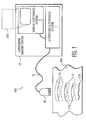
- FIG. 1 illustrates the general diagnostic environment where an improved ultrasound-imaging system may practice the various methods enclosed herein to improve color- flow ultrasound-imaging diagnostics.
- the a general diagnostic environment where the improved ultrasound-imaging system may practice the various methods of improved color-flow imaging is illustrated by way of a schematic diagram in FIG. 1 and is generally denoted by reference numeral 100.
- an ultrasound-imaging system 10 may be disposed in a diagnostic environment 100 comprising a patient under test 113, a transducer 18, and an interface cable 12.
- the transducer 18 may be placed into position over a portion of the anatomy of a patient under test 113 by a user/operator (not shown) of the ultrasound-imaging system 10.
- a plurality of transmit signals may be generated within the ultrasound-electronics system 1 and conveyed to the transducer 18 via the interface cable 12.
- the plurality of transmit signals may be converted to a plurality of transmit pulses 115 that emanate from the transducer 18 in response to the applied transmit signals.
- the multiple transmit pulses 115 When the transmit pulses (ultrasound energy) 115 encounter a tissue layer of the patient under test 113 that is receptive to ultrasound insonification, the multiple transmit pulses 115 penetrate the tissue layer 113. As long as the magnitude of the multiple ultrasound pulses exceeds the attenuation affects of the tissue layer 113, the multiple ultrasound pulses 115 will reach an internal target 121. Those skilled in the art will appreciate that tissue boundaries or intersections between tissues with different ultrasonic impedances will develop ultrasonic responses at the fundamental- transmit frequency of the plurality of ultrasound pulses 115. Tissue insonified with ultrasonic pulses will develop fundamental-ultrasonic responses that may be distinguished in time from the transmit pulses to convey information from the various tissue boundaries within a patient.
- Those ultrasonic reflections 117a, 117b of a magnitude that exceed that of the attenuation affects from traversing tissue layer 113 may be monitored and converted into an electrical signal by the ultrasound-electronics system 1.
- the ultrasound-electronics system 1 and a display-electronics system 5 may work together to produce an ultrasound-display image 200 derived from the plurality of ultrasonic echoes 117.
- tissue boundaries or intersections between tissues with different ultrasonic impedances will develop ultrasonic responses at both the fundamental frequency, as well as at harmonics of the fundamental frequency of the plurality of ultrasound pulses 115.
- Tissue insonified with ultrasonic pulses 115 will develop both fundamental 117a and harmonic ultrasonic responses 117b that may be distinguished in time from the transmit pulses 115 to convey information from the various tissue boundaries within a patient.
- tissue insonified with ultrasonic pulses 115 develops harmonic responses 117b because the compressional portion of the insonified waveforms travels faster than the rarefactional portions. The different rates of travel of the compressional and the rarefactional portions of the waveform causes the wave to distort producing a harmonic signal, which is reflected or scattered back through the various tissue boundaries.
- the ultrasound-imaging system 10 both transmits and receives a plurality of ultrasound pulses 115 at a fundamental frequency.
- harmonic responses 117b may be received by a transducer 18 having an appropriately wide bandwidth to simultaneously transmit at a fundamental frequency and receive associated responses at a harmonic frequency thereof. While fundamental imaging is used, both fundamental and harmonic imaging are contemplated and within the scope of the present invention.
- ultrasonic echoes 117a and 117b reflect fundamental responses and harmonic responses respectively.
- FIG. 1 illustrates a second harmonic response to the incident multiple ultrasound-transmit pulses 115 impinging the internal target 121
- other harmonic responses may also observed.
- subharmonic, harmonic, and ultraharmonic responses may be created at the tissue boundary between a tissue layer 113 and the internal target 121, when the internal target has been perfused with one or more contrast agents.
- the internal target 121 alone will produce harmonic responses at integer multiples of the fundamental frequency.
- Various contrast agents on the other hand, have been shown to produce subharmonic, harmonic, and ultraharmonic responses to incident ultrasonic pulses.
- Those ultrasonic reflections of a magnitude that exceed that of the attenuation affects from traversing tissue layer 113 may be monitored and converted into an electrical signal by the combination of the transducer 18, the interface cable 12, and the ultrasound-electronics system 1 as will be explained in further detail below.
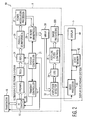
- FIG. 2 The architecture of an ultrasound-imaging system 10 capable of practicing the various contrast-agent imaging methods disclosed below is illustrated by way of a functional-block diagram in FIG. 2 and is generally denoted by reference numeral 10.
- many of the functional blocks illustrated in FIG. 2 define a logical function that can be implemented in hardware, software, or a combination thereof. For purposes of achieving high speed, it is preferred, at present, that most of the blocks be implemented in hardware, unless specifically noted hereafter. It will be appreciated that this figure does not necessarily illustrate every component of the system, emphasis instead being placed upon the components relevant to the methods disclosed herein.
- the ultrasound-imaging system 10 may include an ultrasound-electronics system 1 in communication with a transducer 18 and display-electronics system 5.
- the ultrasound-electronics system 1 may include a system controller 21 designed to control the operation and timing of the various elements and signal flow within the ultrasound-imaging system 10 pursuant to suitable software.
- the ultrasound-electronics system 1 may further comprise a transmit controller 14, a radio-frequency (RF) switch 16, a plurality of preamps 20, time-gain compensators (TGCs) 22, and analog-to-digital converters (ADCs) 24.
- RF radio-frequency
- TGCs time-gain compensators
- ADCs analog-to-digital converters
- the ultrasound-electronics system 1 may comprise a parallel beamformer 26, a power-modulation processor 27, a RF filter 28, a mixer 30, an amplitude detector 32, a log mechanism 34, a post-log filter 36, and one or more image processors 300.
- the display-electronics system 5 may comprise a video processor 40, a video-memory device 42, and a display 44.
- the transducer 18 may take the form of a phased-array transducer having a plurality of elements both in the lateral and elevation directions.
- the plurality of transducer elements may be constructed of a piezoelectric material, for example but not limited to, lead-zirconate-titanate (PZT).
- PZT lead-zirconate-titanate
- Each element may be selectively supplied with an electrical pulse or other suitable electrical waveform, causing the elements to collectively propagate an ultrasound-pressure wave into the object-under-test.
- PZT lead-zirconate-titanate
- Each element may be selectively supplied with an electrical pulse or other suitable electrical waveform, causing the elements to collectively propagate an ultrasound-pressure wave into the object-under-test.
- one or more echoes are reflected by the object-under-test and are received by the transducer 18, which transforms the echoes into an electrical signal for detection and processing within the ultrasound-electronics system 1.
- the array of elements associated with the transducer 18 enable a beam, emanating from the transducer array, to be steered (during transmit and receive modes) through the object by delaying the electrical pulses supplied to the separate elements.
- a transmit mode When a transmit mode is active, an analog waveform is communicated to each transducer element, thereby causing a pulse to be selectively propagated in a particular direction, like a beam, through the object.
- Each analog waveform essentially represents a succession of echoes received by the transducer element over a period of time as echoes are received along the single beam through the object. Time delays are applied to the signals from each element to form a narrow receive beam in the desired direction.
- the entire set of analog waveforms formed by both transmit and receive mode manipulations represents an acoustic line, and the entire set of acoustic lines represents a single view, or image, of an object commonly referred to as a frame.
- a phased-array transducer may comprise a host of internal-electronics responsive to one or more control signals that may originate within the system controller 21 or alternatively in the transmit controller 14.
- the transducer electronics may be configured to select a first subset of transducer elements to apply an excitation signal to generate a plurality of ultrasonic pulses.
- the transducer electronics may be configured to select a second subset of transducer elements to receive ultrasonic echoes related to the transmitted-ultrasonic pulses.
- Each of the aforementioned transducer-element selections may be made by the transducer 18 in response to the one or more control signals originating in the transmit controller 14 or the system controller 21.
- the transmit controller 14 may be electrically connected to the transducer 18 via a RF switch 16.
- the transmit controller 14 may be in further communication with the system controller 21.
- the system controller 21 may be configured to send one or more control signals to direct operation of the transmit controller 14.
- the transmit controller 14 may generate a series of electrical pulses that may be periodically communicated to a portion of the array of elements of the transducer 18 via the RF switch 16, causing the transducer elements to emit ultrasound signals into the object-under-test of the nature described previously.
- the transmit controller 14 typically provides separation between the pulsed transmissions to enable the transducer 18 to receive echoes from the object during the period between transmit pulses and forwards them onto a set of parallel analog preamplifiers 20, herein labeled, "PREAMPs.”
- the RF switch 16 may be configured to direct the various transmit and receive electrical signals to and from the transducer 18.
- the plurality of preamplifiers 20 may receive a series of analog electrical-echo waveforms from the transducer 18 that are generated by echoes reflected from the object-under-test. More specifically, each preamplifier 20 receives an analog electrical-echo waveform from a corresponding set of transducer elements for each acoustic line. Moreover, the set of preamplifiers 20 receives a series of waveform sets, one set for each separate acoustic line, in succession over time and may process the waveforms in a pipeline-processing manner. The set of preamplifiers 20 may be configured to amplify the echo waveforms to provide amplified-echo waveforms to enable further signal processing, as described hereafter. Because the ultrasound signals received by the transducer 18 are of low power, the set of preamplifiers 20 should be of sufficient quality that excessive noise is not generated in the process.
- the plurality of analog preamplifiers 20 in the ultrasound-electronics system 1 may be connected respectively to a parallel plurality of TGCs 22, which are known in the art and are designed to progressively increase the gain during each acoustic line, thereby reducing the dynamic range requirements on subsequent processing stages.
- the set of TGCs 22 may receive a series of waveform sets, one set for each separate acoustic line, in succession over time and may process the waveforms in a pipeline-processing manner.
- a plurality of parallel analog-to-digital converters (ADCs) 24 may be in communication respectively with the plurality of TGCs 22, as shown in FIG. 2 .
- Each of the ADCs 24 may be configured to convert its respective analog-echo waveform into a digital-echo waveform comprising a number of discrete-location points (hundreds to thousands; corresponding with depth and may be a function of ultrasound transmit frequency or time) with respective quantized instantaneous-signal levels, as is well known in the art.
- this conversion often occurred later in the signal processing steps, but now, many of the logical functions that are performed on the ultrasonic signals can be digital, and hence, the conversion is preferred at an early stage in the signal-processing process.
- the plurality of ADCs 24 may receive a series of waveforms for separate acoustic lines in succession over time and process the data in a pipeline-processing manner.
- the system may process signals at a clock rate of 40 MHz with a B-mode frame rate of 60 Hz.
- a set of parallel beamformers 26 may be in communication with the plurality of ADCs 24 and may be designed to receive the multiple digital-echo waveforms (corresponding with each set of transducer elements) from the ADCs 24 and combine them to form a single acoustic line.
- each parallel beamformer 26 may delay the separate echo waveforms by different amounts of time and then may add the delayed waveforms together, to create a composite digital RF-acoustic line.
- the foregoing delay and sum beamforming process is well known in the art.
- the parallel beamformer 26 may receive a series of data collections for separate acoustic lines in succession over time and process the data in a pipeline-processing manner.
- a power-modulation processor 27 may be coupled to the output of the parallel beamformers 26 and may be configured to receive and process a plurality of digital- acoustic lines in succession.
- the power-modulation processor 27 may be configured to work in concert with the system controller 21 or the transmit controller 14 to selectively process a plurality of digital-acoustic lines with multiple levels of ultrasound insonification.
- An example of an ultrasound-imaging system 100 for producing a series of ultrasonic pulses with multiple excitation levels is disclosed in U.S. patent 5,577,505 which shares a common assignee with the present application.
- a RF filter 28 may be coupled to the output of the power-modulation processor 27 as illustrated in FIG. 2 .
- the RF filter 28 may take the form of a bandpass filter configured to receive each digital-acoustic line and to remove undesired out of band noise.
- a mixer 30 may be coupled at the output of the RF filter 28.
- the mixer 30 may be designed to process a plurality of digital-acoustic lines in a pipeline manner.
- the mixer 30 may be configured to combine the filtered digital-acoustic lines from the RF filter 28 with a local oscillator signal (not shown for simplicity) to ultimately produce a plurality of baseband digital-acoustic lines.
- the local oscillator signal is a complex signal, having an in-phase signal (real) and a quadrature-phase signal (imaginary) that are ninety degrees out-of- phase.
- the mixing operation may produce sum and difference frequency signals.
- the sum-frequency signal may be filtered (removed), leaving the difference-frequency signal, which is a complex signal at near zero frequency.
- a complex signal is desired to follow direction of movement of anatomical structures imaged in the object-under-test, and to allow accurate, wide-bandwidth amplitude detection.
- An amplitude detector 32 may receive and process, in pipeline manner, the complex baseband digital-acoustic lines from the mixer 30. For each complex- baseband digital-acoustic line, the amplitude detector 32 may analyze the envelope of the line to determine the signal intensity at each point along the acoustic line to produce an amplitude-detected digital-acoustic line. Mathematically, this means that the amplitude detector 32 determines the magnitude of each phasor (distance to origin) corresponding with each point along the acoustic line.
- a log mechanism 34 may receive the amplitude-detected digital-acoustic lines in a pipeline-processing manner, from the amplitude detector 32.
- the log mechanism 34 may be configured to compress the dynamic range of the data by computing the mathematical logarithm (log) of each acoustic line to produce a compressed digital-acoustic line for further processing.
- log mathematical logarithm
- a post-log filter 36 may be coupled to the output of the log mechanism 34 and may be configured to receive the compressed digital-acoustic lines in a pipeline fashion.
- the post-log filter 36 may remove or suppress high frequencies associated with the compressed digital-acoustic lines to enhance the quality of the display image.
- the post-log filter 36 softens the speckle in the displayed image.
- the low-pass post-log filter 36 can also be configured to perform anti-aliasing.
- the low-pass post-log filter 36 can be designed to essentially trade spatial resolution for gray-scale resolution.
- One or more image processors 300 may be coupled to the output of the low-pass post-log filter 36.
- Each of the image processors 300 may further comprise a suitable species of random-access memory (RAM) and may be configured to receive the filtered digital-acoustic lines from the low-pass post-log filter 36.
- the acoustic lines can be defined within a two-dimensional coordinate space.
- the image processors 300 may be configured to mathematically manipulate image information within the received and filtered digital-acoustic lines.
- each of the image processors 300 may be configured to accumulate acoustic lines of data over time for signal manipulation.
- the image processors 300 may further comprise a scan converter to convert the data as stored in the RAM to produce pixels for display.
- Each scan converter may process the data in the RAM once an entire data frame (i.e ., a set of all acoustic lines in a single view, or image/picture to be displayed) has been accumulated by the RAM. For example, if the received data is stored in RAM using polar coordinates to define the relative location of the echo information, the scan converter may convert the polar-coordinate data into rectangular (orthogonal) data capable of raster scan via a raster-scan capable processor.
- the ultrasound-electronics system 1 having completed the receiving, echo recovery, and image-processing functions, to form a plurality of image frames associated with the plurality of ultrasound-image planes, may forward the echo-image data information associated with each image frame to a display-electronics system 5 as illustrated in FIG. 2 .
- the display-electronics system 5 may receive the echo-image data from the ultrasound-electronics system 1, where the echo-image data may be forwarded to a video processor 40.
- the video processor 40 may be designed to receive the echo- image data information and may be configured to raster scan the image information.
- the video processor 40 outputs picture elements (e.g ., pixels) for storage in a video-memory device 42 and/or for display via a display 44.
- the video-memory device 42 may take the form of a digital-videodisc (DVD) player/recorder, a compact-disc (CD) player/recorder, a video-cassette recorder (VCR), or other video-information storage device.
- DVD digital-videodisc
- CD compact-disc
- VCR video-cassette recorder
- the video-memory device 42 permits viewing and or post-data collection image processing by a user/operator in other than real-time.
- a display device in the form of a display 44 may be in communication with both the video processor 40 and the video memory 42 as illustrated in FIG. 2 .
- the display 44 may be configured to periodically receive the pixel data from either the video memory 42 and or the video processor 40 and drive a suitable screen or other imaging device (e.g ., a printer / plotter) for viewing of the ultrasound image by a user/operator.
- a suitable screen or other imaging device e.g ., a printer / plotter
- power level relates to insonification or acoustic intensity.
- Mechanical index is one parameter used to measure acoustic intensity. Mechanical index is a United States Food and Drug Administration (FDA) regulated parameter defined as peak-rarefactional pressure in megaPascal (Mpa) divided by the square root of the center frequency in megahertz (MHz). Current FDA regulations limit the mechanical index to a maximum of 1.9, after allowing for tissue related frequency dependent attenuation.
- FDA United States Food and Drug Administration
- contrast agents respond differently to various insonification and detection techniques. It is theorized that these different responses can be explained due to flexibility of the shell material used to encase the agent, the size distribution within the body, and the particular characteristics of the gas inside the shell. As a result, determining an effective-mechanical index for a particular application is somewhat patient and agent specific. The mechanical index needs to be low enough to not destroy the contrast agent while maintaining a linear response signal from insonified tissue. On the other hand, the mechanical index needs to be high enough to overcome the effects of tissue attenuation at the fundamental frequency while initiating a non-linear response from the one or more contrast agents. Generally, a mechanical index from 0.05 to 0.5 will meet these requirements for a broad range of contrast agents starting from the most fragile to the more resilient.
- achieving different power levels in each of two or more transmit events or ultrasound lines 115 may be accomplished in several different ways.
- a method of achieving the different power settings is by varying the transmit voltage. Varying transmit voltage has the direct result of varying the pressure amplitude of the resultant transmitted- ultrasound lines 115 (see FIG. 1 ).
- different power levels may be accomplished by controlling the size of the aperture of the transducer 18. The aperture size may be varied in the lateral or elevation dimensions by using a synthetic-aperture methodology. The aperture may be divided into two or more groups with transmit-ultrasound lines 115 being separately fired from each group. The subsequent reflected energy is then stored.
- the scaling step includes beamforming the response from the two or more smaller apertures and subtracting those results from the response due to excitation from the entire aperture to determine the non-linear response.
- Another way of controlling transmitted-power levels is to fire a subset of elements in the array and compare the scaled-subset response to a response from the entire transducer array. This method should be performed in a manner to reduce and or minimize grating lobes that stem from under sampling the aperture and steering errors that result from asymmetries about the center of the aperture.
- a non-limiting example of a multi-pulse technique that fires three pulses is described below. Firing the "even" numbered elements within transducer 18 may generate the first pulse. The second pulse may be generated by controllably firing all elements of the transducer 18. Firing the "odd” numbered elements may generate the third pulse.
- the response signal-processing portion of the ultrasound-electronics system 10 may be configured to mathematically combine a response from the first and third pulses for further mathematical manipulation with the second response signal. It is important to note that the selection of elements to form the various element subsets for the first and third pulses is not limited to "even" and "odd” numbered elements of the transducer element array. It will be appreciated by those skilled in the art that more than three pulses may be generated and fired to further extend a multi-pulse insonification and imaging technique.
- the multi-pulse technique described above serves a couple of purposes.
- adjusting the transmitted power by firing a subset of elements reduces the transmit power while providing the same voltage level to each transmission. If the transmit waveforms are not properly scaled and inverted, or if the waveforms differ in their frequency content, undesired residual artifacts from imperfect tissue-response signal cancellations may be introduced by the ultrasound-electronics system 10.
- the ultrasound-electronics system 10 reduces any undesired tissue signals introduced by mathematically combining signal responses generated from ultrasonic transmissions of varying power levels. Transmit-waveform power-magnitude matching over a number of various levels of comparison across a received bandwidth of interest will serve to reduce residual-tissue response-signal artifacts that may result from transmit- power mismatches.
- a second important result from using the multi-pulse technique is that by mathematically combining the first pulse response with the third pulse response, motion of an organ-of-interest (i.e ., the heart) is averaged, so that when the second pulse response is mathematically processed ( i.e ., subtracted) from the combination of the first and third pulse responses, motion is suppressed between the various pulses.
- an organ-of-interest i.e ., the heart
- phase-inversion techniques are well understood by those skilled in the art of ultrasonic imaging.
- the description of an ultrasonic-imaging system capable of producing, detecting, and image-processing ultrasonic responses that use phase-inversion techniques need not be described to understand the present invention and need not be described herein.
- mathematical post-processing of detected-response signals may vary based on the desired effect of the processing and the phase of the transmitted waveforms responsible for the response signals. By coordinating one or more of the phase, intensity, and frequency content of multiple transmitted pulses with the applicable response processing, motion artifacts between pulses may be substantially reduced.
- Transmitted pressure waves have a reduced magnitude that varies with angular distance.
- the power received at 0.25 degrees will be lower since it is off the peak of the transmitted beam.
- ultrasound image 200 may comprise alphanumeric information in the form of patient identifiers 202, date and time identifiers 204 and scanning parameters 206.
- ultrasound image 200 may comprise a real-time ultrasound image display 210 of structure in a body such as a portion of the circulatory system such as a coronary-blood vessel 212.
- a clinical technician may use a real-time image.
- the image is created from echoes returned from the non-destructive ultrasonic imaging of one or more contrast agents that have been introduced into the bloodstream of the patient.
- real-time contrast-agent images may be acquired at any phase of the heart cycle, not just when the heart is predominately at rest. While the aforementioned real-time imagery of the heart is especially useful in cardiology, variations of this method may prove useful in radiology where anatomical structures are more stationary as well.
- each transmit line normally comprises repeated sequences of waveforms.
- each waveform comprises a Gaussian-modified sinusoid.
- the various transmit lines are fired along the same line-of-sight into the body as indicated in FIG. 4 .
- Each group of lines fired in this direction is referred to as a packet of lines.
- Normally, specific sequences of transmit waveforms are used and repeated multiple times within each packet.
- Each sequence of transmit waveforms is referred to as a sub-packet.
- the response echoes are received. Again, these received signals are digitized so that the data contained therein can be processed in the appropriate manner. Once digitized, these received data may be stored in one or more of the image processors 300 ( FIG. 2 ). Preferably, the data are organized in an array of data points 400 as shown in FIG. 4 .
- the array 400 may comprise as many columns 402 as there are lines in the packet. Each column 402 contains a collection of samples which correlate to a particular transmit line. There are as many rows 404 in the array 400 as there are digitized-data samples along any one of the received lines. Each successive sample along a row 404 is representative of a particular imaging depth, but acquired a full line-time after the previous sample. Normally, the row 404 direction of the array 400 is referred to as slow-time. Each successive data point down each column 402 is acquired immediately after the previous data point in the line. Accordingly, the column direction of the array 400 is referred to as fast-time.
- a correction function is applied to the data to compensate for the variance of the transmit signals across the multiple transmit lines.
- the nature of the correction function may depend upon the particular modulation scheme used to vary the transmit signals. For instance, if the transmit signals were varied according to amplitude (i.e., power modulation), the correction function can comprise a scaling factor which accounts for the amplitude variance across the signal lines. If phase modulation was used in creating the transmit signals, the correction function can comprise a phase adjustment which accounts for the phase variance of the transmit signal. Similarly, where the transmit signals were varied in polarity, the correction can comprise inverting the receive data for the positive or the negative transmit lines.
- the various lines of data can be subtracted from the other, for instance with a contrast-imaging clutter filter, to cancel the linear components of the data.
- the response of moving tissue is suppressed.
- the received-echo data will not cancel precisely, and some residual signal due from moving tissue will remain. Therefore, it is preferable to compensate for this motion before attempting to cancel the linear signals of moving tissue from the received data.
- a power modulated multi-line subpacket having the following transmit sequence: 0, L, H, L, 0 may be applied by the ultrasound-electronics system 1 ( FIG. 2 ).
- the initial blank line allows time for reverberation from a previous imaging line to die out.
- a FIR filter may then be applied to combine the slow-time samples 404 with weighted values: 0, -1, 1, -1, 1. This filtering results in the substantial reduction of tissue-generated signals and reverberation signals, while having little or no effect on signals from contrast-agent bubbles.
- image processors 300 may comprise a B-mode processor 310, a Doppler processor 320, an improved color-flow processor 400, as well as other image processors. As shown in the functional-block diagram of FIG.
- the image processors 300 may be inserted in the architecture of the ultrasound-electronics system 10 generally after beamforming (i.e., the parallel beamformers 26) and prior to scan conversion and video processing ( i.e ., in the display-electronics system 5).
- each of the image processors 300 may be configured with its own scan converter (not shown). It will be further appreciated that one or more scan converters may be provided in association with one or more of the various image processors 310, 320, 400.
- An improved color-flow processor 400 is illustrated via a functional-block diagram in FIG. 6 .
- the improved color-flow processor 400 may comprise a clutter filter 500 in combination with a color-flow processor 410 known in the art.
- the improved color-flow processor 400 may be introduced after parallel beamforming and prior to scan conversion.
- FIG. 7 further illustrates the operation of the clutter filter 500 introduced in FIG. 6 .
- the power-modulation processor 27 of the ultrasound-electronics system 10 may be configured to transmit the exemplar power-modulated transmit sequence illustrated across the top of FIG. 7 .
- the power- modulated transmit sequence may comprise the following 13 line packet: 0, L, H, L, 0, L, H, L, 0, L, H, L, 0.
- 0 indicates no transmit pulse is sent;
- L indicates that a half-power transmit pulse is sent;
- H indicates that a full-power transmit pulse is applied to the tissue of interest.
- the clutter filter 500 for the exemplar 13 line transmit sequence may provide two output samples for color-flow processing with the weights as illustrated in FIG. 7 .
- the clutter filter 500 applied to each sample is a one-zero filter (with a sample spacing of four slow-time samples).
- the cumulative effect of the two filters and the power-modulation technique(s) is to reduce tissue generation signals and stationary contrast-bubble signals, while passing signals generated from moving contrast-agent bubbles.
- the relative phase of the two data points from the exemplar line sequence 13 of FIG. 7 can then be evaluated to compute a velocity estimate of the contrast-agent bubbles.
- the technique described above can also be applied to Doppler-imaging modes including phased-array pulsed-wave (PW) Doppler.
- PW phased-array pulsed-wave
- an improved color-flow processor 800 may comprise a clutter filter 500, a color-flow processor 410, a tissue-signal processor 810, a mathematical junction 820, and an arbiter 830. As previously described in association with FIG. 6 , the improved color-flow processor 800 may also be inserted in the ultrasound-electronics system 10 of FIG. 2 generally after beamforming (i.e., the parallel beamformers 26) and prior to scan conversion and video processing (i.e., in the display-electronics system 5). As previously described in association with FIG. 2 , it will be appreciated that the improved color-flow processor 800 may be configured with its own scan converter (not shown).
- the improved color-flow processor 800 can be constructed by providing a secondary-processing path, not entirely separate from the path previously described with regard to the improved color-flow processor of FIG. 6 .
- the secondary-processing path may comprise a first branch that enters a tissue-signal processor 810 before being forwarded to the mathematical junction 820.
- a primary branch or color-flow-processing path may be formed by the clutter filter 500, the color-flow processor 410, and a signal from an image processor.
- the signal from the image processor and the output of the color-flow processor 410 are processed by the arbiter 830 before being forwarded to the mathematical junction 820.
- the secondary-processing path is designed to measure the velocity of the tissue generated echo signals rather than the blood with the contrast agent.
- the tissue-generated echo signals can be applied to the tissue-signal processor 810 to generate a tissue-velocity signal formed from the same set of acoustic lines (i.e ., the same subpacket data) as the power-modulated color-flow signal.
- the tissue-signal processor 810 will employ a different set of coefficients in its own clutter filter (not shown).
- the tissue-signal processor coefficients could, for example, select equal power lines from each subpacket, such as the "H" transmit lines and coefficients of 0 for the lower-power "L” transmit lines.
- the tissue-signal processor 810 would then produce the same output-sample rate as the clutter filter 500, and could be processed by the same phase-detection steps as the color-flow signal.
- the signal that exits the color-flow processor 410 is processed along with the underlying image data from a two-dimensional image processor (e.g ., black and white image data as supplied by a B-mode processor).
- a two-dimensional image processor e.g ., black and white image data as supplied by a B-mode processor.
- the color-flow velocity samples are rendered instead of the underlying image-data samples.
- the improved color-flow processor 800 the arbitration between the color-flow velocity samples and the underlying image-data samples would remain unchanged, but where color-flow velocity samples are selected for display, the tissue-velocity signal would be subtracted.
- the improved color-flow processor 800 would provide a signal over time that suppresses the tissue "flash" artifact along with providing information regarding the velocity of contrast agents corrected for surrounding tissue motion.
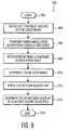
- FIG. 9 illustrates a flowchart describing a method for contrast-agent enhanced color-flow imaging that may be implemented by the ultrasound-electronics system 10 of FIG. 2 .
- the method for contrast-agent enhanced color-flow imaging 900 may begin with step 902, labeled "START.”
- one or more contrast agents may be introduced into a patient's bloodstream as indicated in step 904.
- These contrast agents can comprise microbubbles of a heavy gas, such as a perfluorocarbon-gas encapsulated in an outer shell made of protein, lipid, or other suitable material.
- the size of the agents may vary depending upon the application, these microbubbles normally are in the range of approximately 1.0 to 15 microns ( ⁇ m) in diameter.
- the contrast agents are introduced into the bloodstream, they travel throughout the cardiovascular system.
- the ultrasound-electronics system 10 may be configured to transmit a series of power- modulated ultrasound signals into the body as shown in step 906.
- the ultrasound-electronics system 10 is configured to receive the series of ultrasonic echoes induced by the power-modulated transmit signals.
- step 910 non-linear tissue responses can be suppressed using power-modulation techniques as previously described hereinabove.
- the various data can be processed using a color-flow-processing algorithm as shown in step 912. It is significant to note that the color-flow-processing will include processing by the clutter filter 500 to reduce the effect of echo signals generated by stationary contrast-agent bubbles, while passing signals generated by moving bubbles.
- the relative phase of the multiple data points generated in the clutter filter 500 are then evaluated to generate a velocity estimate according to well-known color-flow processing techniques.
- the color-flow processing may include generating a color-encoded display of contrast-agent velocities. It will be appreciated that the color-encoded display may be rendered along with data generated in a B-mode processor to enable identification of the tissue structures imaged.
- the method for contrast-agent enhanced color-flow imaging 900 may terminate.
- steps 906 through 914 may be repeated as desired to diagnose various blood vessels of various sizes within the patient. It will be further appreciated that if desired, step 904 may be repeated or continuously performed by introducing the one or more contrast agents via an intravenous line and commercially available infusers.
- imaging of the one or more contrast agents can comprise simply imaging the concentration of the contrast agents within human tissue, or can comprise color-flow processing as described above to identify the direction and velocity of flow of contrast agents within the bloodstream or tissues.
- the techniques described herein compensate for the response of non-moving contrast-agent bubbles, as well as, non-moving tissue. These adjustments are beneficial in that it is now possible to differentiate slowly moving blood flows from surrounding tissue. It will be appreciated that the velocity of contrast agent in the blood is of particular clinical significance, especially when imaging structures such as the heart. As described above, the effects of moving tissue can be substantial, especially when areas near or within the heart are being imaged. Notably, patient breathing, coughing, or other such movements can also create tissue movement. Regardless of the source of the movement, however, it is preferable that this movement is reduced, or compensated for, such that those flash artifacts that degrade the imaging of the contrast agents are suppressed.
- contrast-agent enhanced color-flow imaging 900 is suited to any insonification technique, which suppresses tissue-signal responses at the fundamental frequency of a significant magnitude so that non-linear responses from a contrast image can be detected and color-flow processed to identify direction and velocity.
- FIG. 10 presents a flow chart highlighting a method for contrast-agent enhanced color-flow imaging with a tissue-velocity adjustment.
- the method for contrast-agent enhanced color-flow imaging with correction for tissue velocity 1000 presented in FIG. 10 reflects the same steps of "start" 1002, introducing one or more contrast agents 1004, transmitting a series of power modulated ultrasound pulses 1006, and receiving/processing the ultrasound echoes received from the body.
- start 1002
- the method for contrast-agent enhanced color-flow imaging with correction for tissue velocity 1000 branches.
- a first branch is formed by steps 1010, 1012, and 1014.
- a second branch is formed by steps 1011 and step 1020, where the first and second processing branches combine.
- a power-modulation technique is used to suppress non-linear tissue responses as illustrated in step 1010.
- the various contrast-agent induced echo signals can be processed using a color-flow-processing algorithm as shown in step 1012.
- the color-flow-processing may include processing by the clutter filter 500 as described hereinabove.
- processing may also include generating a color-encoded display of contrast-agent velocities.
- a tissue-signal motion processor and a related clutter filter with its own set of coefficients may be used to determine a tissue velocity as shown in step 1011.
- the tissue velocity determined in step 1011 may be buffered for use later in step 1020 as described below.
- the method for contrast-agent enhanced color-flow imaging with correction for tissue velocity 1000 may be configured to compare the contrast-agent color-flow processed velocities with a threshold value. If the velocity samples exceed the threshold, processing may continue with step 1020, where the contrast-agent velocity value is corrected by subtracting the tissue velocity determined in step 1011.
- the method for contrast-agent enhanced color-flow imaging with correction for tissue velocity may drop the color-flow processed sample as indicated in step 1018.
- the color-encoded display may be rendered along with data generated in a B-mode processor to enable identification of the tissue structures imaged.
- the method for contrast-agent enhanced color-flow imaging with correction for tissue velocity 1000 may terminate.
- steps 1006 through 1020 may be repeated as desired to diagnose various blood vessels of various sizes within the patient.
- step 1004 may be repeated or continuously performed by introducing the one or more contrast agents via an intravenous line as previously described.
- the techniques described herein compensate for the response of non-moving contrast-agent bubbles, as well as, moving and non-moving tissue generated echoes. These adjustments are beneficial in that it is now possible to differentiate slowly moving blood flows from surrounding tissue while compensating for local tissue movement. Significantly, quantitative assessment of blood flow velocities relative to the surrounding tissue, rather than relative to the transducer 18 face are possible.
- the improved color-flow processors 400, 800 described above can be implemented in software, hardware, or a combination thereof within the ultrasound-electronics system 1 shown in FIGs. 1 and 2 .
- the improved color-flow processors 400, 800 can be stored and transported on any computer-readable medium for use by or in connection with an instruction-execution system, apparatus, or device, such as a computer-based system, processor-containing system, or other system that can fetch the instructions from the instruction-execution system, apparatus, or device and execute the instructions.
- a "computer-readable medium” can be any means that can contain, store, communicate, propagate, or transport the program for use by or in connection with the instruction-execution system, apparatus, or device.
- the computer-readable medium can be, for example, an electronic, magnetic, optical, electromagnetic, infrared, or semiconductor system, apparatus, device, or propagation medium. More specific examples of computer-readable media include the following: an electrical connection having one or more wires, computer diskette, random-access memory (RAM), read-only memory (ROM), erasable-programmable read-only memory (EPROM or Flash memory), an optical fiber, and a compact-disk read-only memory (CD ROM).
- the computer-readable medium can even be paper or other suitable media upon which the program is printed as the program can be electronically captured, via for instance optical scanning of the paper or other media, then compiled, interpreted, or otherwise processed and stored in a computer memory.
- the improved color-flow processors 400, 800 can be implemented with any or a combination of the following technologies, which are all well known in the art: a discrete-logic circuit(s) having logic gates for implementing logic functions upon data signals, an application-specific integrated circuit (ASIC) having appropriate combinational logic gates, a programmable-gate array(s) (PGA), a field-programmable gate array (FPGA), etc.
- ASIC application-specific integrated circuit
- PGA programmable-gate array
- FPGA field-programmable gate array
Landscapes
- Physics & Mathematics (AREA)
- Engineering & Computer Science (AREA)
- Health & Medical Sciences (AREA)
- Life Sciences & Earth Sciences (AREA)
- Remote Sensing (AREA)
- Radar, Positioning & Navigation (AREA)
- Computer Networks & Wireless Communication (AREA)
- General Physics & Mathematics (AREA)
- Radiology & Medical Imaging (AREA)
- Nonlinear Science (AREA)
- Medical Informatics (AREA)
- Molecular Biology (AREA)
- Surgery (AREA)
- Animal Behavior & Ethology (AREA)
- General Health & Medical Sciences (AREA)
- Public Health (AREA)
- Veterinary Medicine (AREA)
- Heart & Thoracic Surgery (AREA)
- Biomedical Technology (AREA)
- Pathology (AREA)
- Nuclear Medicine, Radiotherapy & Molecular Imaging (AREA)
- Biophysics (AREA)
- Acoustics & Sound (AREA)
- Hematology (AREA)
- Ultra Sonic Daignosis Equipment (AREA)
Claims (13)
- Ultraschall-Bildgebungssystem mit:- einer Anregungssignalquelle, die so konfiguriert ist, dass sie eine Sequenz leistungsmodulierter Sendelinien erzeugt;- einem Wandler, der mit der Anregungssignalquelle verbunden ist, wobei der Wandler so konfiguriert ist, dass er als Reaktion auf die Sequenz leistungsmodulierter Sendelinien eine Vielzahl von Ultraschallimpulsen in ein Medium aussendet und eine Vielzahl von empfangenen Ultraschallechos als Reaktion sowohl auf Gewebe als auch auf einen oder mehrere Kontrastmittel in dem Medium in eine Vielzahl von Echosignalen umwandelt;- einem Ultraschall-Prozessorsystem, das mit dem Wandler verbunden ist, wobei das Ultraschall-Prozessorsystem so konfiguriert ist, dass es vom Gewebe erzeugte Ultraschallechosignale reduziert und stationäre, von Kontrastmittel erzeugte Ultraschallechosignale reduziert, während es Ultraschallechosignale, die von sich bewegendem Kontrastmittel erzeugt werden, weiterleitet; und- ein Anzeige-Prozessorsystem, das mit dem Ultraschall-Prozessorsystem verbunden ist, wobei das Anzeige-Prozessorsystem so ausgelegt ist, dass es als Reaktion auf die von sich bewegendem Kontrastmittel erzeugten Ultraschallechosignale eine grafische Darstellung empfängt und erzeugt;dadurch gekennzeichnet, dass das Ultraschall-Bildgebungssystem ferner Folgendes umfasst:- einen Gewebegeschwindigkeitsprozessor, der mit dem Ultraschall-Prozessorsystem verbunden ist, wobei der Gewebegeschwindigkeitsprozessor so konfiguriert ist, dass er als Reaktion auf von Bewegung vom Gewebe erzeugten Ultraschallechosignalen ein erstes Ausgangssignal erzeugt;- einen Arbiter, der mit einem zweiten Ausgangssignal von einem Color-Flow-Prozessor und einem dritten Ausgangssignal von zumindest einem einer Vielzahl von 2D-Bildprozessoren verbunden ist, wobei der Arbiter so konfiguriert ist, dass er das zweite Ausgangssignal von dem Color-Flow-Prozessor weiterleitet, wenn die Intensität des zweiten Ausgangssignals einen Schwellenwert überschreitet; und- einen Rechenknoten, der mit einem Ausgang des Arbiters und dem ersten Ausgangssignal verbunden ist, wobei der Rechenknoten so konfiguriert ist, dass er eine Subtraktion des ersten Ausgangssignals von dem zweiten Ausgangssignal vornimmt.
- System nach Anspruch 1, wobei Ultraschallechos vom Körper eines Patienten empfangen werden und das Reduzieren der von Gewebe erzeugten Echosignale die Anwendung eines FIR- (Finite Impulse Response) Filters auf die empfangenen Ultraschallechos umfasst.
- System nach Anspruch 1, wobei die Reduzierung der von Gewebe erzeugten Ultraschallechosignale ein Leistungsmodulationsverfahren umfasst, das Subpakete aus mehreren Sendelinien nutzt.
- System nach Anspruch 1, wobei die Bildgebung das Zuführen der durch sich bewegendes Kontrastmittel erzeugten Ultraschallechosignale zu einem Color-Flow-Prozessor umfasst.
- System nach Anspruch 1, wobei die Reduzierung von vom stationären Kontrastmittel erzeugten Ultraschallechosignalen das Anwenden eines ersten Stördatenfilters (engl. Clutter Filter) umfasst.
- System nach Anspruch 3, wobei das Leistungsmodulationsverfahren das wiederholte Aussenden der aus mehreren Sendelinien bestehenden Subpakete umfasst.
- System nach Anspruch 4, wobei der Color-Flow-Prozessor als Reaktion auf die Bewegungsrichtung und die -geschwindigkeit des sich bewegenden Kontrastmittels Informationen erzeugt.
- System nach Anspruch 5, wobei das erste Stördatenfilter ein Eins-Null-Filter (engl. One Zero Filter) umfasst.
- System nach Anspruch 8, wobei das Eins-Null-Filter ein zeitversetztes Filter über mehrere Abtastwerte ist, die von einer Vielzahl von Ultraschallechosignalen erzeugt werden.
- System nach Anspruch 7, das ferner Folgendes umfasst:- Mittel zum Ermitteln der Gewebegeschwindigkeit, und- Mittel zum Kombinieren der Gewebegeschwindigkeit mit den Informationen als Reaktion auf die Bewegungsrichtung und -geschwindigkeit des sich bewegenden Kontrastmittels.
- System nach Anspruch 10, wobei die Ermittlung der Gewebegeschwindigkeit das Zuführen der empfangenen Ultraschallechosignale zu einem zweiten Stördatenfilter vor den Mitteln zum Reduzieren von durch Gewebe erzeugten Ultraschallechosignalen umfasst.
- System nach Anspruch 11, wobei die Sequenz leistungsmodulierter Sendelinien aus Sendesignalen erzeugt wird, die unterschiedliche Spannungsamplituden oder Polaritäten oder Phasen aufweisen.
- Verfahren zur Abbildung von Kontrastmitteln, das Folgendes umfasst:- Senden von leistungsmodulierten Ultraschallimpulsen mit einer vorbestimmten Sendesequenz mit einer Vielzahl von Sendelinien in den Körper eines Patienten;- Empfangen einer Vielzahl von Ultraschallechos mit von Kontrastmittel erzeugten Echos und von Gewebe erzeugten Echos aus dem Körper des Patienten;- Verarbeiten der empfangenen Ultraschallechos zum Erzeugen einer Vielzahl von Ultraschallechosignalen als Reaktion sowohl auf die von Kontrastmittel erzeugten als auch auf die von Gewebe erzeugten Echos;- Verarbeiten der Vielzahl von Ultraschallechosignalen zum Unterdrücken der von Gewebe erzeugten Echos;- Verarbeiten der Vielzahl von Ultraschallechosignalen zum Unterdrücken der von stationärem Kontrastmittel erzeugten Echos;- Zuführen der Vielzahl der von Kontrastmittel erzeugten Echosignale zu einem Color-Flow-Algorithmus zum Erzeugen einer Vielzahl von Datenpunkten als Reaktion auf die Bewegung des Kontrastmittels; und- Anzeigen der Vielzahl von Datenpunkten über die Zeit;dadurch gekennzeichnet, dass das Verfahren ferner die folgenden Schritte umfasst:- Erzeugen einer farbcodierten Anzeige der Kontrastmittelgeschwindigkeiten;- Ermitteln der Gewebegeschwindigkeit;- Vergleichen der mit Color-Flow verarbeiteten Geschwindigkeiten des Kontrastmittels mit einem Schwellenwert;- Korrigieren des Wertes der Geschwindigkeit des Kontrastmittels durch Subtrahieren der ermittelten Gewebegeschwindigkeit, wenn die Abtastwerte für die Geschwindigkeit den Schwellenwert überschreiten;- Auslassen des mit Color-Flow verarbeiteten Abtastwertes, wenn die Geschwindigkeitsabtastwerte den Schwellenwert nicht überschreiten.
Applications Claiming Priority (3)
| Application Number | Priority Date | Filing Date | Title |
|---|---|---|---|
| US134164 | 2002-04-26 | ||
| US10/134,164 US6638228B1 (en) | 2002-04-26 | 2002-04-26 | Contrast-agent enhanced color-flow imaging |
| PCT/IB2003/001412 WO2003090624A1 (en) | 2002-04-26 | 2003-04-07 | Contrast-agent enhanced color-flow imaging |
Publications (2)
| Publication Number | Publication Date |
|---|---|
| EP1501419A1 EP1501419A1 (de) | 2005-02-02 |
| EP1501419B1 true EP1501419B1 (de) | 2012-06-13 |
Family
ID=29249151
Family Applications (1)
| Application Number | Title | Priority Date | Filing Date |
|---|---|---|---|
| EP03710155A Expired - Lifetime EP1501419B1 (de) | 2002-04-26 | 2003-04-07 | Mit kontrastmittel verstärkte farbliche darstellung von strömungen |
Country Status (5)
| Country | Link |
|---|---|
| US (2) | US6638228B1 (de) |
| EP (1) | EP1501419B1 (de) |
| JP (1) | JP2005523743A (de) |
| AU (1) | AU2003214575A1 (de) |
| WO (1) | WO2003090624A1 (de) |
Families Citing this family (62)
| Publication number | Priority date | Publication date | Assignee | Title |
|---|---|---|---|---|
| US6951542B2 (en) | 2002-06-26 | 2005-10-04 | Esaote S.P.A. | Method and apparatus for ultrasound imaging of a biopsy needle or the like during an ultrasound imaging examination |
| US6638228B1 (en) * | 2002-04-26 | 2003-10-28 | Koninklijke Philips Electronics N.V. | Contrast-agent enhanced color-flow imaging |
| US6986792B2 (en) | 2002-09-13 | 2006-01-17 | Smith & Nephew, Inc. | Prostheses |
| ITFI20030077A1 (it) * | 2003-03-26 | 2004-09-27 | Actis Active Sensors S R L | Metodo per l'indagine ecografica tramite mezzi di contrasto |
| WO2005074805A1 (en) * | 2004-02-05 | 2005-08-18 | Koninklijke Philips Electronics N.V. | Ultrasonic imaging of perfusion and blood flow with harmonic contrast agents |
| US7004906B1 (en) * | 2004-07-26 | 2006-02-28 | Siemens Medical Solutions Usa, Inc. | Contrast agent imaging with agent specific ultrasound detection |
| US8278799B1 (en) * | 2004-07-27 | 2012-10-02 | Vincent Lupien | System and method for optimizing the design of an ultrasonic transducer |
| US11457813B2 (en) | 2005-03-29 | 2022-10-04 | Martin W. Roche | Method for detecting body parameters |
| US20110213221A1 (en) | 2005-03-29 | 2011-09-01 | Roche Martin W | Method for Detecting Body Parameters |
| CA2600613C (en) * | 2005-03-29 | 2016-10-25 | Martin Roche | Body parameter detecting sensor and method for detecting body parameters |
| CN101163987B (zh) * | 2005-04-18 | 2012-06-13 | 皇家飞利浦电子股份有限公司 | 由探头固件配置的超声诊断成像系统 |
| US7837626B2 (en) * | 2005-08-05 | 2010-11-23 | Siemens Medical Solutions Usa, Inc. | Contrast agent manipulation with medical ultrasound imaging |
| US7998076B2 (en) * | 2005-09-27 | 2011-08-16 | Siemens Medical Solutions Usa, Inc. | Advanced characterization of contrast agents with ultrasound |
| KR100868483B1 (ko) * | 2005-10-07 | 2008-11-12 | 주식회사 메디슨 | 초음파영상 디스플레이 방법 |
| US8932225B2 (en) * | 2006-01-26 | 2015-01-13 | Kabushiki Kaisha Toshiba | Ultrasonic diagnostic apparatus and ultrasonic diagnostic method |
| US20080021321A1 (en) * | 2006-05-22 | 2008-01-24 | Siemens Medical Solutions Usa, Inc. | Contrast agent destruction or therapy event indication in ultrasound medical imaging |
| EP2076179B1 (de) * | 2006-08-01 | 2018-07-04 | Stichting voor de Technische Wetenschappen | Impulsumkehrungssequenzen für nichtlineare bildgebung |
| WO2008075299A1 (en) | 2006-12-19 | 2008-06-26 | Koninklijke Philips Electronics, N.V. | Combined photoacoustic and ultrasound imaging system |
| US20080214934A1 (en) | 2007-03-02 | 2008-09-04 | Siemens Medical Solutions Usa, Inc. | Inter-frame processing for contrast agent enhanced medical diagnostic ultrasound imaging |
| US7713209B2 (en) * | 2007-05-21 | 2010-05-11 | Siemens Medical Solutions Usa, Inc. | Targeted contrast agent imaging with medical diagnostic ultrasound |
| CA2692889A1 (en) | 2007-07-11 | 2009-01-15 | Robert J. Daley | Methods and apparatus for determining pin placement during hip surgery |
| EP2051070A1 (de) * | 2007-10-18 | 2009-04-22 | Siemens Aktiengesellschaft | Verfahren und Vorrichtung zur zerstörungsfreien Materialprüfung eines Prüfgegenstandes mit Ultraschallwellen |
| US20090187106A1 (en) * | 2008-01-23 | 2009-07-23 | Siemens Medical Solutions Usa, Inc. | Synchronized combining for contrast agent enhanced medical diagnostic ultrasound imaging |
| US8668648B2 (en) | 2008-01-23 | 2014-03-11 | Siemens Medical Solutions Usa, Inc. | Contrast agent destruction effectiveness determination for medical diagnostic ultrasound imaging |
| US20090204003A1 (en) * | 2008-02-07 | 2009-08-13 | Guracar Ismayil M | Tracking selection for medical diagnostic ultrasound imaging |
| WO2009130647A1 (en) * | 2008-04-24 | 2009-10-29 | Koninklijke Philips Electronics N.V. | Motion compensated micro-vasculature imaging |
| KR101100498B1 (ko) * | 2008-08-05 | 2011-12-29 | 삼성메디슨 주식회사 | 컬러맵을 형성하는 초음파 시스템 및 방법 |
| JP5395396B2 (ja) * | 2008-10-15 | 2014-01-22 | 株式会社東芝 | 超音波診断装置、医用画像処理装置、及び医用画像処理プログラム |
| US20100113926A1 (en) * | 2008-10-31 | 2010-05-06 | General Electric Company | System and method for clutter filter processing for improved adaptive beamforming |
| US20110144495A1 (en) * | 2009-12-14 | 2011-06-16 | Siemens Medical Solutions Usa, Inc. | Perfusion Imaging of a Volume in Medical Diagnostic Ultrasound |
| WO2011096556A1 (ja) * | 2010-02-08 | 2011-08-11 | 株式会社 日立メディコ | 超音波診断装置、及び血流画像生成方法 |
| US9066674B2 (en) * | 2010-03-17 | 2015-06-30 | Siemens Medical Solutions Usa, Inc. | Motion synchronized destruction for three-dimensional reperfusion mapping in medical diagnostic ultrasound imaging |
| JP5637725B2 (ja) * | 2010-04-12 | 2014-12-10 | キヤノン株式会社 | 音響波イメージング装置 |
| KR101120794B1 (ko) | 2010-06-01 | 2012-03-22 | 삼성메디슨 주식회사 | 움직임 영상을 제공하는 초음파 시스템 |
| WO2011152260A1 (ja) * | 2010-06-04 | 2011-12-08 | 株式会社日立メディコ | 超音波診断装置 |
| US8956301B2 (en) | 2011-02-04 | 2015-02-17 | Siemens Medical Solutions Usa, Inc. | Optimization of lines per second for medical diagnostic ultrasound contrast agent imaging |
| AU2012258902A1 (en) * | 2011-05-20 | 2014-01-16 | Doheny Eye Institute | Ocular ultrasound probe |
| JP5868026B2 (ja) * | 2011-05-24 | 2016-02-24 | 株式会社東芝 | 超音波診断装置 |
| US11116892B2 (en) | 2012-08-28 | 2021-09-14 | Osprey Medical, Inc. | Medium injection diversion and measurement |
| US10010673B2 (en) | 2012-08-28 | 2018-07-03 | Osprey Medical, Inc. | Adjustable medium diverter |
| US9320846B2 (en) | 2012-08-28 | 2016-04-26 | Osprey Medical, Inc. | Devices and methods for modulating medium delivery |
| US10022497B2 (en) | 2012-08-28 | 2018-07-17 | Osprey Medical, Inc. | Reservoir for collection and reuse of diverted medium |
| US9999718B2 (en) | 2012-08-28 | 2018-06-19 | Osprey Medical, Inc. | Volume monitoring device utilizing light-based systems |
| US10413677B2 (en) | 2012-08-28 | 2019-09-17 | Osprey Medical, Inc. | Volume monitoring device |
| US11219719B2 (en) | 2012-08-28 | 2022-01-11 | Osprey Medical, Inc. | Volume monitoring systems |
| EP2938265B1 (de) * | 2012-12-28 | 2023-02-15 | Philips Image Guided Therapy Corporation | Intravaskuläre ultraschallbildgebungsvorrichtung |
| US20140324354A1 (en) * | 2013-04-29 | 2014-10-30 | King Fahd University Of Petroleum And Minerals | Transmission coefficient method for avo seismic analysis |
| US10034657B2 (en) | 2013-07-26 | 2018-07-31 | Siemens Medical Solutions Usa, Inc. | Motion artifact suppression for three-dimensional parametric ultrasound imaging |
| EP3097432B1 (de) * | 2014-01-23 | 2022-07-06 | Supersonic Imagine | Verfahren zur bestimmung eines physikalischen merkmals an einer punktuellen position innerhalb eines mediums, verfahren zur bestimmung eines bildes eines mediums und vorrichtung zur umsetzung dieser verfahren |
| CN117694922A (zh) * | 2015-01-29 | 2024-03-15 | 皇家飞利浦有限公司 | 宽带混合的基波和谐波频率超声诊断成像 |
| US10987089B2 (en) | 2015-11-05 | 2021-04-27 | Samsung Medison Co., Ltd. | Ultrasound imaging apparatus and method of generating ultrasound image |
| US10859687B2 (en) | 2016-03-31 | 2020-12-08 | Butterfly Network, Inc. | Serial interface for parameter transfer in an ultrasound device |
| US11154279B2 (en) | 2016-03-31 | 2021-10-26 | Bfly Operations, Inc. | Transmit generator for controlling a multilevel pulser of an ultrasound device, and related methods and apparatus |
| CN109564279B (zh) * | 2016-08-04 | 2023-10-13 | 皇家飞利浦有限公司 | 具有用于阵列换能器的脉冲发生器和线性放大器的超声系统前端电路 |
| US10716545B2 (en) * | 2016-12-22 | 2020-07-21 | Fujifilm Sonosite, Inc. | Ultrasound system for imaging and protecting ophthalmic or other sensitive tissues |
| CN110582242B (zh) | 2017-05-03 | 2023-03-10 | 美敦力瓦斯科尔勒公司 | 组织移除导管 |
| US11690645B2 (en) | 2017-05-03 | 2023-07-04 | Medtronic Vascular, Inc. | Tissue-removing catheter |
| EP3860466B1 (de) * | 2018-10-04 | 2023-08-09 | Koninklijke Philips N.V. | Strömungsdetektion für ultraschallabbildungsvorrichtungen, systeme und verfahren |
| CN118697424A (zh) | 2018-11-16 | 2024-09-27 | 美敦力瓦斯科尔勒公司 | 组织去除导管 |
| US11499841B2 (en) | 2019-04-12 | 2022-11-15 | Osprey Medical, Inc. | Energy-efficient position determining with multiple sensors |
| US11819236B2 (en) | 2019-05-17 | 2023-11-21 | Medtronic Vascular, Inc. | Tissue-removing catheter |
| EP4173572A1 (de) * | 2021-10-29 | 2023-05-03 | SuperSonic Imagine | Verfahren und system zur bestimmung einer physikalischen eigenschaft eines mediums |
Family Cites Families (12)
| Publication number | Priority date | Publication date | Assignee | Title |
|---|---|---|---|---|
| US5410516A (en) | 1988-09-01 | 1995-04-25 | Schering Aktiengesellschaft | Ultrasonic processes and circuits for performing them |
| US5113706A (en) * | 1990-07-03 | 1992-05-19 | Hewlett-Packard Company | Ultrasound system with dynamic transmit focus |
| US5456257A (en) * | 1994-11-23 | 1995-10-10 | Advanced Technology Laboratories, Inc. | Ultrasonic detection of contrast agents |
| US5566674A (en) * | 1995-06-30 | 1996-10-22 | Siemens Medical Systems, Inc. | Method and apparatus for reducing ultrasound image shadowing and speckle |
| US5577505A (en) | 1996-02-06 | 1996-11-26 | Hewlett-Packard Company | Means for increasing sensitivity in non-linear ultrasound imaging systems |
| US5833614A (en) * | 1997-07-15 | 1998-11-10 | Acuson Corporation | Ultrasonic imaging method and apparatus for generating pulse width modulated waveforms with reduced harmonic response |
| US5860931A (en) * | 1997-10-10 | 1999-01-19 | Acuson Corporation | Ultrasound method and system for measuring perfusion |
| US5980459A (en) * | 1998-03-31 | 1999-11-09 | General Electric Company | Ultrasound imaging using coded excitation on transmit and selective filtering of fundamental and (sub)harmonic signals on receive |
| US6186950B1 (en) * | 1999-11-04 | 2001-02-13 | Atl Ultrasound | Ultrasonic pulse inversion harmonic separation with reduced motional effects |
| US6224557B1 (en) * | 2000-02-03 | 2001-05-01 | Agilent Technologies, Inc. | Ultrasonic method using adaptive clutter filter to remove tissue wall motion |
| US6468216B1 (en) * | 2000-08-24 | 2002-10-22 | Kininklijke Philips Electronics N.V. | Ultrasonic diagnostic imaging of the coronary arteries |
| US6638228B1 (en) * | 2002-04-26 | 2003-10-28 | Koninklijke Philips Electronics N.V. | Contrast-agent enhanced color-flow imaging |
-
2002
- 2002-04-26 US US10/134,164 patent/US6638228B1/en not_active Expired - Lifetime
-
2003
- 2003-04-07 JP JP2003587269A patent/JP2005523743A/ja active Pending
- 2003-04-07 WO PCT/IB2003/001412 patent/WO2003090624A1/en not_active Ceased
- 2003-04-07 EP EP03710155A patent/EP1501419B1/de not_active Expired - Lifetime
- 2003-04-07 AU AU2003214575A patent/AU2003214575A1/en not_active Abandoned
- 2003-08-05 US US10/634,366 patent/US6969353B2/en not_active Expired - Lifetime
Also Published As
| Publication number | Publication date |
|---|---|
| AU2003214575A1 (en) | 2003-11-10 |
| US6638228B1 (en) | 2003-10-28 |
| US6969353B2 (en) | 2005-11-29 |
| US20030204142A1 (en) | 2003-10-30 |
| JP2005523743A (ja) | 2005-08-11 |
| US20040030253A1 (en) | 2004-02-12 |
| WO2003090624A1 (en) | 2003-11-06 |
| EP1501419A1 (de) | 2005-02-02 |
Similar Documents
| Publication | Publication Date | Title |
|---|---|---|
| EP1501419B1 (de) | Mit kontrastmittel verstärkte farbliche darstellung von strömungen | |
| US6827686B2 (en) | System and method for improved harmonic imaging | |
| EP0948931B1 (de) | Ultraschallabbildung mittels kodierter Anregung beim Senden und selektiver Filterung beim Empfang | |
| EP1517636B1 (de) | Kontrastmittelunterstützte bildgebung mit synchronisierter persistenz | |
| US5014710A (en) | Steered linear color doppler imaging | |
| EP0947853B1 (de) | Verfahren und Anlage zur verbesserten Ultraschall-B-Bild-Strombilderzeugung | |
| US5873829A (en) | Diagnostic ultrasound system using harmonic echo imaging | |
| EP0952462A2 (de) | Verfahren und Anordnung zur Verbesserung der Anzeige von Biopsiekanülen in Ultraschall-Bilddarstelllung | |
| US6814703B2 (en) | Apparatus and method for ultrasonic diagnostic imaging using a contrast medium | |
| EP3537980B1 (de) | Dreifachmodus-ultraschallbildgebung zur anatomischen, funktionalen und hämodynamischen bildgebung | |
| US20080242992A1 (en) | Ultrasound Imaging System and Method for Flow Imaging Using Real-Time Spatial Compounding | |
| US20040064043A1 (en) | Continuous depth harmonic imaging using transmitted and nonlinearly generated second harmonics | |
| US6652463B2 (en) | System and method for non-linear detection of ultrasonic contrast agents at a fundamental frequency | |
| EP1003051A2 (de) | Ultraschall- Bilderzeugungsgerät | |
| JP4574790B2 (ja) | 超音波診断装置及び超音波診断方法 | |
| US6371914B1 (en) | Single-shot phase cancellation ultrasound contrast imaging | |
| US20040127795A1 (en) | Method of ultrasonic speckle reduction using wide-band frequency compounding with tissue-generated harmonics | |
| EP1146351A1 (de) | Ultraschallkontrastbildformung mittels Doppelpulsanregungswellenformen | |
| EP3905961B1 (de) | Kontrastbildgebung | |
| US7803114B2 (en) | Ultrasonic diagnostic apparatus and data processing method therefor |
Legal Events
| Date | Code | Title | Description |
|---|---|---|---|
| PUAI | Public reference made under article 153(3) epc to a published international application that has entered the european phase |
Free format text: ORIGINAL CODE: 0009012 |
|
| 17P | Request for examination filed |
Effective date: 20041126 |
|
| AK | Designated contracting states |
Kind code of ref document: A1 Designated state(s): AT BE BG CH CY CZ DE DK EE ES FI FR GB GR HU IE IT LI LU MC NL PT RO SE SI SK TR |
|
| AX | Request for extension of the european patent |
Extension state: AL LT LV MK |
|
| 17Q | First examination report despatched |
Effective date: 20050413 |
|
| GRAP | Despatch of communication of intention to grant a patent |
Free format text: ORIGINAL CODE: EPIDOSNIGR1 |
|
| GRAS | Grant fee paid |
Free format text: ORIGINAL CODE: EPIDOSNIGR3 |
|
| GRAA | (expected) grant |
Free format text: ORIGINAL CODE: 0009210 |
|
| AK | Designated contracting states |
Kind code of ref document: B1 Designated state(s): AT BE BG CH CY CZ DE DK EE ES FI FR GB GR HU IE IT LI LU MC NL PT RO SE SI SK TR |
|
| REG | Reference to a national code |
Ref country code: GB Ref legal event code: FG4D |
|
| REG | Reference to a national code |
Ref country code: CH Ref legal event code: EP Ref country code: AT Ref legal event code: REF Ref document number: 561616 Country of ref document: AT Kind code of ref document: T Effective date: 20120615 |
|
| REG | Reference to a national code |
Ref country code: IE Ref legal event code: FG4D |
|
| REG | Reference to a national code |
Ref country code: DE Ref legal event code: R096 Ref document number: 60341248 Country of ref document: DE Effective date: 20120809 |
|
| REG | Reference to a national code |
Ref country code: DE Ref legal event code: R084 Ref document number: 60341248 Country of ref document: DE Effective date: 20120706 |
|
| REG | Reference to a national code |
Ref country code: NL Ref legal event code: VDEP Effective date: 20120613 |
|
| PG25 | Lapsed in a contracting state [announced via postgrant information from national office to epo] |
Ref country code: FI Free format text: LAPSE BECAUSE OF FAILURE TO SUBMIT A TRANSLATION OF THE DESCRIPTION OR TO PAY THE FEE WITHIN THE PRESCRIBED TIME-LIMIT Effective date: 20120613 Ref country code: CY Free format text: LAPSE BECAUSE OF FAILURE TO SUBMIT A TRANSLATION OF THE DESCRIPTION OR TO PAY THE FEE WITHIN THE PRESCRIBED TIME-LIMIT Effective date: 20120613 Ref country code: SE Free format text: LAPSE BECAUSE OF FAILURE TO SUBMIT A TRANSLATION OF THE DESCRIPTION OR TO PAY THE FEE WITHIN THE PRESCRIBED TIME-LIMIT Effective date: 20120613 |
|
| REG | Reference to a national code |
Ref country code: AT Ref legal event code: MK05 Ref document number: 561616 Country of ref document: AT Kind code of ref document: T Effective date: 20120613 |
|
| PG25 | Lapsed in a contracting state [announced via postgrant information from national office to epo] |
Ref country code: SI Free format text: LAPSE BECAUSE OF FAILURE TO SUBMIT A TRANSLATION OF THE DESCRIPTION OR TO PAY THE FEE WITHIN THE PRESCRIBED TIME-LIMIT Effective date: 20120613 Ref country code: GR Free format text: LAPSE BECAUSE OF FAILURE TO SUBMIT A TRANSLATION OF THE DESCRIPTION OR TO PAY THE FEE WITHIN THE PRESCRIBED TIME-LIMIT Effective date: 20120914 |
|
| PG25 | Lapsed in a contracting state [announced via postgrant information from national office to epo] |
Ref country code: CZ Free format text: LAPSE BECAUSE OF FAILURE TO SUBMIT A TRANSLATION OF THE DESCRIPTION OR TO PAY THE FEE WITHIN THE PRESCRIBED TIME-LIMIT Effective date: 20120613 Ref country code: RO Free format text: LAPSE BECAUSE OF FAILURE TO SUBMIT A TRANSLATION OF THE DESCRIPTION OR TO PAY THE FEE WITHIN THE PRESCRIBED TIME-LIMIT Effective date: 20120613 Ref country code: BE Free format text: LAPSE BECAUSE OF FAILURE TO SUBMIT A TRANSLATION OF THE DESCRIPTION OR TO PAY THE FEE WITHIN THE PRESCRIBED TIME-LIMIT Effective date: 20120613 Ref country code: SK Free format text: LAPSE BECAUSE OF FAILURE TO SUBMIT A TRANSLATION OF THE DESCRIPTION OR TO PAY THE FEE WITHIN THE PRESCRIBED TIME-LIMIT Effective date: 20120613 Ref country code: EE Free format text: LAPSE BECAUSE OF FAILURE TO SUBMIT A TRANSLATION OF THE DESCRIPTION OR TO PAY THE FEE WITHIN THE PRESCRIBED TIME-LIMIT Effective date: 20120613 Ref country code: AT Free format text: LAPSE BECAUSE OF FAILURE TO SUBMIT A TRANSLATION OF THE DESCRIPTION OR TO PAY THE FEE WITHIN THE PRESCRIBED TIME-LIMIT Effective date: 20120613 |
|
| PG25 | Lapsed in a contracting state [announced via postgrant information from national office to epo] |
Ref country code: PT Free format text: LAPSE BECAUSE OF FAILURE TO SUBMIT A TRANSLATION OF THE DESCRIPTION OR TO PAY THE FEE WITHIN THE PRESCRIBED TIME-LIMIT Effective date: 20121015 |
|
| PG25 | Lapsed in a contracting state [announced via postgrant information from national office to epo] |
Ref country code: NL Free format text: LAPSE BECAUSE OF FAILURE TO SUBMIT A TRANSLATION OF THE DESCRIPTION OR TO PAY THE FEE WITHIN THE PRESCRIBED TIME-LIMIT Effective date: 20120613 |
|
| PLBE | No opposition filed within time limit |
Free format text: ORIGINAL CODE: 0009261 |
|
| STAA | Information on the status of an ep patent application or granted ep patent |
Free format text: STATUS: NO OPPOSITION FILED WITHIN TIME LIMIT |
|
| PG25 | Lapsed in a contracting state [announced via postgrant information from national office to epo] |
Ref country code: ES Free format text: LAPSE BECAUSE OF FAILURE TO SUBMIT A TRANSLATION OF THE DESCRIPTION OR TO PAY THE FEE WITHIN THE PRESCRIBED TIME-LIMIT Effective date: 20120924 Ref country code: DK Free format text: LAPSE BECAUSE OF FAILURE TO SUBMIT A TRANSLATION OF THE DESCRIPTION OR TO PAY THE FEE WITHIN THE PRESCRIBED TIME-LIMIT Effective date: 20120613 |
|
| 26N | No opposition filed |
Effective date: 20130314 |
|
| REG | Reference to a national code |
Ref country code: DE Ref legal event code: R097 Ref document number: 60341248 Country of ref document: DE Effective date: 20130314 |
|
| PG25 | Lapsed in a contracting state [announced via postgrant information from national office to epo] |
Ref country code: BG Free format text: LAPSE BECAUSE OF FAILURE TO SUBMIT A TRANSLATION OF THE DESCRIPTION OR TO PAY THE FEE WITHIN THE PRESCRIBED TIME-LIMIT Effective date: 20120913 |
|
| PG25 | Lapsed in a contracting state [announced via postgrant information from national office to epo] |
Ref country code: MC Free format text: LAPSE BECAUSE OF FAILURE TO SUBMIT A TRANSLATION OF THE DESCRIPTION OR TO PAY THE FEE WITHIN THE PRESCRIBED TIME-LIMIT Effective date: 20120613 |
|
| REG | Reference to a national code |
Ref country code: CH Ref legal event code: PL |
|
| GBPC | Gb: european patent ceased through non-payment of renewal fee |
Effective date: 20130407 |
|
| REG | Reference to a national code |
Ref country code: IE Ref legal event code: MM4A |
|
| PG25 | Lapsed in a contracting state [announced via postgrant information from national office to epo] |
Ref country code: CH Free format text: LAPSE BECAUSE OF NON-PAYMENT OF DUE FEES Effective date: 20130430 Ref country code: LI Free format text: LAPSE BECAUSE OF NON-PAYMENT OF DUE FEES Effective date: 20130430 Ref country code: GB Free format text: LAPSE BECAUSE OF NON-PAYMENT OF DUE FEES Effective date: 20130407 |
|
| REG | Reference to a national code |
Ref country code: DE Ref legal event code: R082 Ref document number: 60341248 Country of ref document: DE Representative=s name: VOLMER, GEORG, DIPL.-ING., DE |
|
| PG25 | Lapsed in a contracting state [announced via postgrant information from national office to epo] |
Ref country code: IE Free format text: LAPSE BECAUSE OF NON-PAYMENT OF DUE FEES Effective date: 20130407 |
|
| REG | Reference to a national code |
Ref country code: DE Ref legal event code: R082 Ref document number: 60341248 Country of ref document: DE Representative=s name: MEISSNER, BOLTE & PARTNER GBR, DE Effective date: 20140328 Ref country code: DE Ref legal event code: R082 Ref document number: 60341248 Country of ref document: DE Representative=s name: MEISSNER BOLTE PATENTANWAELTE RECHTSANWAELTE P, DE Effective date: 20140328 Ref country code: DE Ref legal event code: R081 Ref document number: 60341248 Country of ref document: DE Owner name: KONINKLIJKE PHILIPS N.V., NL Free format text: FORMER OWNER: KONINKLIJKE PHILIPS ELECTRONICS N.V., EINDHOVEN, NL Effective date: 20120618 Ref country code: DE Ref legal event code: R081 Ref document number: 60341248 Country of ref document: DE Owner name: KONINKLIJKE PHILIPS N.V., NL Free format text: FORMER OWNER: KONINKLIJKE PHILIPS ELECTRONICS N.V., EINDHOVEN, NL Effective date: 20140328 Ref country code: DE Ref legal event code: R082 Ref document number: 60341248 Country of ref document: DE Representative=s name: VOLMER, GEORG, DIPL.-ING., DE Effective date: 20140328 |
|
| REG | Reference to a national code |
Ref country code: FR Ref legal event code: CD Owner name: KONINKLIJKE PHILIPS ELECTRONICS N.V., NL Effective date: 20141126 Ref country code: FR Ref legal event code: CA Effective date: 20141126 |
|
| PG25 | Lapsed in a contracting state [announced via postgrant information from national office to epo] |
Ref country code: HU Free format text: LAPSE BECAUSE OF FAILURE TO SUBMIT A TRANSLATION OF THE DESCRIPTION OR TO PAY THE FEE WITHIN THE PRESCRIBED TIME-LIMIT; INVALID AB INITIO Effective date: 20030407 Ref country code: LU Free format text: LAPSE BECAUSE OF NON-PAYMENT OF DUE FEES Effective date: 20130407 |
|
| REG | Reference to a national code |
Ref country code: DE Ref legal event code: R082 Ref document number: 60341248 Country of ref document: DE Representative=s name: MEISSNER, BOLTE & PARTNER GBR, DE Ref country code: DE Ref legal event code: R082 Ref document number: 60341248 Country of ref document: DE Representative=s name: MEISSNER BOLTE PATENTANWAELTE RECHTSANWAELTE P, DE |
|
| REG | Reference to a national code |
Ref country code: FR Ref legal event code: PLFP Year of fee payment: 14 |
|
| REG | Reference to a national code |
Ref country code: FR Ref legal event code: PLFP Year of fee payment: 15 |
|
| REG | Reference to a national code |
Ref country code: FR Ref legal event code: PLFP Year of fee payment: 16 |
|
| PGFP | Annual fee paid to national office [announced via postgrant information from national office to epo] |
Ref country code: TR Payment date: 20180405 Year of fee payment: 16 |
|
| PGFP | Annual fee paid to national office [announced via postgrant information from national office to epo] |
Ref country code: DE Payment date: 20210428 Year of fee payment: 19 Ref country code: FR Payment date: 20210427 Year of fee payment: 19 Ref country code: IT Payment date: 20210422 Year of fee payment: 19 |
|
| PG25 | Lapsed in a contracting state [announced via postgrant information from national office to epo] |
Ref country code: TR Free format text: LAPSE BECAUSE OF NON-PAYMENT OF DUE FEES Effective date: 20190407 |
|
| REG | Reference to a national code |
Ref country code: DE Ref legal event code: R119 Ref document number: 60341248 Country of ref document: DE |
|
| PG25 | Lapsed in a contracting state [announced via postgrant information from national office to epo] |
Ref country code: FR Free format text: LAPSE BECAUSE OF NON-PAYMENT OF DUE FEES Effective date: 20220430 Ref country code: DE Free format text: LAPSE BECAUSE OF NON-PAYMENT OF DUE FEES Effective date: 20221103 |
|
| PG25 | Lapsed in a contracting state [announced via postgrant information from national office to epo] |
Ref country code: IT Free format text: LAPSE BECAUSE OF NON-PAYMENT OF DUE FEES Effective date: 20220407 |