EP1501013A2 - System und Verfahren zur Echtzeit periodischen Aufgabenablaufsteuerung - Google Patents
System und Verfahren zur Echtzeit periodischen Aufgabenablaufsteuerung Download PDFInfo
- Publication number
- EP1501013A2 EP1501013A2 EP04015759A EP04015759A EP1501013A2 EP 1501013 A2 EP1501013 A2 EP 1501013A2 EP 04015759 A EP04015759 A EP 04015759A EP 04015759 A EP04015759 A EP 04015759A EP 1501013 A2 EP1501013 A2 EP 1501013A2
- Authority
- EP
- European Patent Office
- Prior art keywords
- task
- task group
- thread
- group
- execution
- Prior art date
- Legal status (The legal status is an assumption and is not a legal conclusion. Google has not performed a legal analysis and makes no representation as to the accuracy of the status listed.)
- Withdrawn
Links
Images


Classifications
-
- G—PHYSICS
- G06—COMPUTING OR CALCULATING; COUNTING
- G06F—ELECTRIC DIGITAL DATA PROCESSING
- G06F9/00—Arrangements for program control, e.g. control units
- G06F9/06—Arrangements for program control, e.g. control units using stored programs, i.e. using an internal store of processing equipment to receive or retain programs
- G06F9/46—Multiprogramming arrangements
- G06F9/48—Program initiating; Program switching, e.g. by interrupt
- G06F9/4806—Task transfer initiation or dispatching
- G06F9/4843—Task transfer initiation or dispatching by program, e.g. task dispatcher, supervisor, operating system
- G06F9/4881—Scheduling strategies for dispatcher, e.g. round robin, multi-level priority queues
- G06F9/4887—Scheduling strategies for dispatcher, e.g. round robin, multi-level priority queues involving deadlines, e.g. rate based, periodic
-
- G—PHYSICS
- G06—COMPUTING OR CALCULATING; COUNTING
- G06F—ELECTRIC DIGITAL DATA PROCESSING
- G06F9/00—Arrangements for program control, e.g. control units
- G06F9/06—Arrangements for program control, e.g. control units using stored programs, i.e. using an internal store of processing equipment to receive or retain programs
- G06F9/44—Arrangements for executing specific programs
- G06F9/455—Emulation; Interpretation; Software simulation, e.g. virtualisation or emulation of application or operating system execution engines
- G06F9/45533—Hypervisors; Virtual machine monitors
- G06F9/45537—Provision of facilities of other operating environments, e.g. WINE
-
- G—PHYSICS
- G06—COMPUTING OR CALCULATING; COUNTING
- G06F—ELECTRIC DIGITAL DATA PROCESSING
- G06F9/00—Arrangements for program control, e.g. control units
- G06F9/06—Arrangements for program control, e.g. control units using stored programs, i.e. using an internal store of processing equipment to receive or retain programs
- G06F9/46—Multiprogramming arrangements
- G06F9/50—Allocation of resources, e.g. of the central processing unit [CPU]
- G06F9/5061—Partitioning or combining of resources
- G06F9/5066—Algorithms for mapping a plurality of inter-dependent sub-tasks onto a plurality of physical CPUs
Definitions
- each operation needs completing within the limit of allowed time.
- a real-time operation including a combination of a plurality of chained tasks periodically at regular time intervals, all the chained tasks need completing within the time interval of each period. However, they cannot be completed if the chained tasks of the real-time operation are long.
- An object of the present invention is to provide a method and an information processing system capable of performing a real-time operation including a combination of a plurality of chained tasks with efficiency using a plurality of processors.
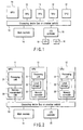
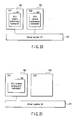
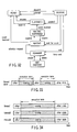
- the memory management unit 22 of the MPU 11 and the memory controllers 33 of the VPUs 12 perform virtual memory management as shown in FIG. 3.
- the address viewed from the processing unit 21 of the MPU 11 or the memory controllers 33 of the VPUs 12 is a 64-bit address as indicated in the upper part of FIG. 3.
- an upper 36-bit portion indicates a segment number
- a middle 16-bit portion indicates a page number
- a lower 12-bit portion indicates a page offset.
- the memory management unit 22 and memory controllers 33 each include a segment table 50 and a page table 60.
- the segment table 50 and page table 60 convert the 64-bit address into the real address space that is actually accessed through the connecting device 13.
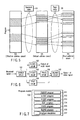
- the following data items are mapped in the real address (RA) space viewed from the MPU 11 and each VPU 12, as shown in FIG. 4.
- RA real address
- FIG. 5 shows memory address spaces managed by the virtual memory management function shown in FIG. 3. It is the EA (effective address) space that is viewed directly from the programs executed on the MPU 11 or VPUs 12. An effective address is mapped in the VA (virtual address) space by the segment table 50. A virtual address is mapped in the RA (real address) space by the page table 60.
- the RA space has a structure as shown in FIG. 4.
- the computer system allows software to perform such an operation of an electric device that makes a stringent demand on real-time operations as conventionally implemented.
- one VPU 12 carries out a computation corresponding to some hardware components that compose the electric device and concurrently another VPU 12 carries out a computation corresponding to other hardware components that compose the electric device.
- a program corresponding to the thread dispatched to the VPU 12 is loaded to the local storage 32 of the VPU 12, and the thread executes the program on the local storage 32.
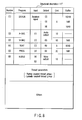
- the program module 100 is obtained by packaging the programs 111 to 116, which correspond to hardware modules for configuring a receiver for digital TV broadcast, with data called a structural description 117.
- the structural description 117 shows modules (programs in the program module 100) each executed as a thread and their corresponding inputs, outputs, execution costs, and buffer sizes necessary for the outputs.
- the V-DEC program of No. (3) receives the output of the DEMUX program of No. (1) as an input and transmits its output to the PROG program of No. (5).
- the buffer necessary for the output of the V-DEC program is 1 MB and the cost for executing the V-DEC program in itself is 50.
- the cost can be described in units of time (time period) necessary for executing the program, or step number of the program. It also can be described in units of time required for executing the program by a virtual processor having some virtual specifications. Since the VPU specifications and performance may vary from computer to computer, it is desirable to describe the cost in such virtual units. If the programs are executed according to the structural description 117 shown in FIG. 8, data flows among the programs as illustrated in FIG. 9.
- the structural description 117 also shows coupling attribute information which indicates a coupling attribute between threads corresponding to the programs 111 to 116 as thread parameters.
- the coupling attribute includes two different attributes of a tightly coupled attribute and a loosely coupled attribute.
- a plurality of threads having the tightly coupled attribute are executed in cooperation with each other and referred to as a tightly coupled thread group.
- the computer system of the present embodiment schedules the threads belonging to each tightly coupled thread group such that the threads belonging to the same tightly coupled thread group can simultaneously be executed by different VPUs.
- a plurality of threads having the loosely coupled attribute is referred to as a loosely coupled thread group.
- a programmer can designate a coupling attribute between threads corresponding to the programs 11 to 16 using thread parameters.
- the tightly and loosely coupled thread groups will be described in detail with reference to FIG. 25 et seq.
- the thread parameters including the coupling attribute information can be described directly as codes in the programs 111 to 116, not as the structural description 117.
- FIGS. 10 and 11 there now follows descriptions as to how the computer system of the present embodiment executes the programs 111 to 116.
- the computer system includes two VPUs of VPU0 and VPU1.
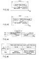
- FIG. 10 shows time for assigning the programs to each of the VPUs when video data of 30 frames is displayed per second. Audio and video data for one frame is output within a time interval corresponding to one period.
- the VPU0 executes the DEMUX program to perform the DEMUX operation and writes its resultant audio, video and subtitle data to the buffers.
- the VPU1 executes the A-DEC program and TEXT program to perform the A-DEC operation and the TEXT operation in sequence and writes their results to the buffers.
- scheduling An operation to determine which program is executed by each of the VPUs and when it is done to perform a desired operation without delay is called scheduling.
- a module to carry out the scheduling is called a scheduler.
- the scheduling is carried out based on the above structural description 117 contained in the program module 100.
- both execution start timing and execution term of each of threads that execute the programs 111 to 116 are determined based on the structural description 117, thereby to assign each of the threads to one or more VPUs 12. The following operations are performed when the program module 100 is to be executed.
- the execution start timing and execution term of each of threads (DEMUX, V-DEC, A-DEC, TEXT, PROG and BLEND) that executes the chained programs 111 to 116 in the program module 100 are determined based on the structural description 117.
- the threads for performing a real-time operation can efficiently be scheduled without describing timing constraint conditions of each operation in codes of a program.
- FIG. 11 shows the programs executed when video data of 60 frames is displayed per second.
- FIG. 11 differs from FIG. 10 as follows.
- data of 60 frames needs to be processed per second, whereas in FIG. 10, data of 30 frames is processed per second and thus data processing for one frame can be completed in one period (1/30 second).
- one-frame data processing cannot be completed in one period (1/60 second) and thus a software pipeline operation that spans a plurality of (two) periods is performed in FIG. 11.
- the VPU0 executes the DEMUX program and V-DEC program for the input signal.
- the VPU1 executes the A-DEC, TEXT, PROG and BLEND programs and outputs final video data.
- the VPU0 executes the DEMUX and V-DEC programs in the next frame.
- the DEMUX and V-DEC programs of the VPU0 and the A-DEC, TEXT, PROG and BLEND programs of the VPU1 are executed over two periods in pipeline mode.
- the two processors VPU1 and VPU2 can execute the second task group in parallel. For example, while the VPU1 executes the tasks A-DEC and TEXT of the second task group, the VPU2 executes the tasks PROG and BLEND of the second task group.
- the program module 100 shown in FIG. 7 can be prerecorded in a flash ROM and a hard disk in a device incorporating the computer system of the present embodiment, or circulated through a network.
- the contents of operations to be performed by the computer system vary according to the type of a program module downloaded through the network.
- the device incorporating the computer system can perform the real-time operation corresponding to each of various pieces of dedicated hardware. If new player software, decoder software and encryption software necessary for reproducing new contents are distributed together with the contents as program modules executable by the computer system, any device incorporating the computer system can reproduce the contents within acceptable limits of ability.
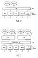
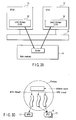
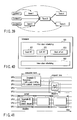
- a virtual machine system can perform a plurality of OSes at once.
- a virtual machine OS 301 is loaded into the computer system to manage all real resources (MPU 11, VPUs 12, memory 14, I/O controller 15, I/O device 16, etc.).
- the virtual machine OS 301 is also referred to as a host OS.
- One or more OSes 302 and 303 that are also referred to as guest OSes are loaded on the virtual machine OS 301.
- the guest OSes 302 and 303 each run on a computer including virtual machine resources given by the virtual machine OS 301 and provide various services to application programs managed by the guest OSes 302 and 303.
- FIG. 13 a virtual machine OS 301 is loaded into the computer system to manage all real resources (MPU 11, VPUs 12, memory 14, I/O controller 15, I/O device 16, etc.).
- the virtual machine OS 301 is also referred to as a host OS.
- One or more OSes 302 and 303 that are also referred to as guest OSes are
- the guest OS 302 appears as if it operated on a computer including one MPU 11, two VPUs 12 and one memory 14, and the guest OS 303 appears as if it operated on a computer including one MPU 11, four VPUs 12 and one memory 14.
- the virtual machine OS 301 manages which one of VPUs 12 of the real resources actually corresponds to a VPU 12 viewed from the guest OS 302 and a VPU 12 viewed from the guest OS 303.
- the guest OSes 302 and 303 need not be aware of the correspondence.
- the virtual machine OS 301 schedules the guest OSes 302 and 303 to allocate all the resources in the computer system to the guest OSes 302 and 303 on a time-division basis. Assume that the guest OS 302 carries out a real-time operation. To perform the operation thirty times per second at an exact pace, the guest OS 302 sets its parameters to the virtual machine OS 301. The virtual machine OS 301 schedules the guest OS 302 to reliably assign necessary operation time to the guest OS 302 once per 1/30 second. The operation time is assigned to a guest OS that does not require a real-time operation by priority lower than a guest OS that requires a real-time operation. FIG.
- FIG. 16 shows an operation mode different from that in FIG. 15.
- a VPU 12 be used continuously according to target applications. This case corresponds to, for example, an application that necessitates continuing to monitor data and events all the time.
- the scheduler of the virtual machine OS 301 manages the schedule of a specific guest OS such that the guest OS occupies a specific VPU 12.
- a VPU 3 is designated as a resource exclusively for a guest OS 302 (OS1). Even though the virtual machine OS 301 switches the guest OS 302 (OS1) and guest OS 303 (OS2) to each other, the VPU 3 always continues to operate under the control of the guest OS 302 (OS1).
- a software module called a VPU runtime environment is used.
- the software module includes a scheduler for scheduling threads to be assigned to the VPUs 12.
- a VPU runtime environment 401 is implemented on the OS 201 as illustrated in FIG. 17.
- the VPU runtime environment 401 can be implemented in the kernel of the OS 201 or in a user program. It can also be divided into two for the kernel and user program to run in cooperation with each other.
- the following modes are provided to implement the VPU runtime environment 401:
- VPU runtime environment can be shared among a plurality of guest OSes, a new VPU runtime environment need not be created when a new guest OS is introduced.
- a scheduler for the VPUs can be shared among guest OSes on the virtual machine OS, the scheduling can be performed efficiently and finely and the resources can be used effectively;
- VPU runtime environment can be shared among a plurality of guest OSes, a new VPU runtime environment need not be created when a new guest OS is introduced;
- VPU runtime environment can optimally be implemented in each guest OS, the scheduling can be performed efficiently and finely and the resources can be used effectively.
- VPU runtime environment need not be implemented in all the guest OSes, a new guest OS is easy to add.
- the VPU runtime environment 401 provides various services (a communication function using a network, a function of inputting/outputting files, calling a library function such as a codec, interfacing with a user, an input/output operation using an I/O device, reading of date and time, etc.) as well as functions of managing and scheduling various resources (operation time of each VPU, a memory, bandwidth of a connection device, etc.) associated with the VPUs 12.
- These services are called from application programs running on the VPUs 12. If a simple service is called, it is processed by service programs on the VPUs 12. A service that cannot be processed only by the VPUs 12, such as communication processing and file processing, is processed by service programs on the MPU 11.
- the programs that provide such services are referred to as a service provider (SP).
- SP service provider
- FIG. 22 shows one example of the VPU runtime environment.
- the principal part of the VPU runtime environment is present on the MPU 11 and corresponds to an MPU-side VPU runtime environment 501.
- a VPU-side VPU runtime environment 502 is present on each of the VPUs 12 and has only the minimum function of carrying out a service that can be processed in the VPU 12.
- the function of the MPU-side VPU runtime environment 501 is roughly divided into a VPU controller 511 and a service broker 512.
- the VPU controller 511 chiefly provides a management mechanism, a synchronization mechanism, a security management mechanism and a scheduling mechanism for various resources (operation time of each VPU, a memory, a virtual space, bandwidth of a connection device, etc.) associated with the VPUs 12. It is the VPU controller 511 that dispatches programs to the VPUs 12 based on the results of scheduling. Upon receiving a service request called by the application program on each VPU 12, the service broker 512 calls an appropriate service program (service provider) and provides the service.
- service provider service provider
- the VPU-side VPU runtime environment 502 Upon receiving a service request called by the application program on each VPU 12, the VPU-side VPU runtime environment 502 processes only services that are processable in the VPU 12 and requests the service broker 512 to process services that are not processable therein.
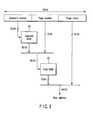
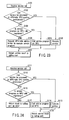
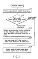
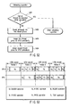
- FIG. 24 shows a procedure for processing a service that is requested by the VPU-side VPU runtime environment 502 by the service broker 512 of the MPU-side VPU runtime environment 501.
- the service broker 512 determines whether the VPU runtime environment 501 can process the service (step S112). If the service can be processed, the service broker 512 executes the service and returns its result to the VPU-side VPU runtime environment 502 of the calling part (steps S113 and S114). If not, the service broker 512 determines whether a service program that can execute the service is registered as one executable on the MPU 11 (step S114).
- the destination of the reply is usually a thread that issues a service request; however, another thread, a thread group or a process can be designated as the destination of the reply. It is thus favorable that the destination be included in a message to request a service.
- the service broker 512 can be realized using a widely used object request broker.
- the computer system serves as a real-time processing system.
- the operations to be performed by the real-time processing system are roughly divided into the following three types:
- the thread has the following three classes:
- This thread class is used for an application whose quality simply lowers even if the timing requirements are not met.
- This thread class is used for an application including no timing requirements.
- the thread is a unit of execution for the real-time operation.
- the threads have their related programs that are to be executed by the threads.
- Each of the threads holds its inherent information that is called a thread context.
- the thread context contains, for example, information of a stack and values stored in the register of the processor.
- MPU 11 and VPU 12 processors that execute the threads and their models are identical with each other.
- the thread context of the VPU thread includes the contents of the local storage 32 of the VPU 12 and the conditions of a DMA controller of the memory controller 33.
- a group of threads is called a thread group.
- the thread group has the advantage of efficiently and easily performing, e.g., an operation of giving the same attribute to the threads of the group.
- the thread group in the hard or soft real-time class is roughly divided into a tightly coupled thread group and a loosely coupled thread group.
- the tightly coupled thread group and loosely coupled thread group are discriminated from each other by attribute information (coupling attribute information) added to the thread groups.
- the coupling attribute of the thread groups can explicitly be designated by the codes in the application programs or the above-described structural description.
- the tightly coupled thread group is a thread group that is made up of threads running in cooperation with each other.
- the threads belonging to the tightly coupled thread group tightly collaborate with each other.
- the tightly collaboration implies an interaction such as frequent communication and synchronization between threads or an interaction that decreases in latency.
- the threads belonging to the same tightly coupled thread group are always executed simultaneously.
- the loosely coupled thread group is a thread group that obviates a tightly collaboration between threads belonging to the group.
- the threads belonging to the loosely coupled thread group carry out communications for transferring data through the buffer on the memory 14.
- a tightly coupled thread group includes two tightly coupled threads A and B, and the threads A and B are executed at once by the VPU0 and VPU1, respectively.
- the real-time processing system of the present embodiment ensures that the threads A and B are executed at once by different VPUs.
- One of the threads can directly communicate with the other thread through a local storage or control register of the VPU that executes the other thread.
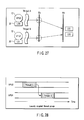
- FIG. 26 illustrates communication between threads A and B, which is performed through the local storages of VPU0 and VPU1 that execute the threads A and B, respectively.
- an RA space corresponding to the local storage 32 of the VPU1 that executes the thread B is mapped in part of an EA space of the thread A.
- an address translation unit 331 provided in the memory controller 33 of the VPU0 performs address translation using a segment table and page table.
- the address translation unit 331 converts (translates) a part of the EA space of the thread A to the RA space corresponding to the local storage 32 of the VPU1, thereby to map the RA space corresponding to the local storage 32 of the VPU1 in part of the EA space of the thread A.
- FIG. 27 shows mapping of local storage (LS1) 32 of the VPU1 executing the thread B in the EA space of the thread A executed by the VPU0 and mapping of local storage (LS0) 32 of the VPU0 executing the thread A in the EA space of the thread B executed by the VPU1.
- the thread A sets a flag indicative of this preparation in the local storage LS0 of the VPU0 or the local storage LS1 of the VPU1 that executes the thread B.
- the thread B reads the data from the local storage LS0.
- the thread C executed by the VPU0 writes data, which is prepared in the local storage LS0, to the buffer prepared on the main memory 14 by DMA transfer.
- the thread D executed by the VPU1 reads data from the buffer on the main memory 14 and writes it to the local storage LS1 by DMA transfer when the thread D starts to run.
- the existing thread (which is one for creating a new thread, i.e., a parent thread of the new thread) first designates a program to be executed by a new thread and causes the new thread to start to execute the program. The program is then stored in the local storage of the VPU and starts to run from a given address.
- the scheduler in the VPU runtime environment 401 checks a coupling attribute between threads based on coupling attribute information added to each group of threads to be scheduled (step S121).
- the scheduler determines whether each thread group is a tightly coupled thread group or a loosely coupled thread group (step S122).
- the coupling attribute is checked referring to the descriptions of threads in program codes or thread parameters in the above structural description 117. If the tightly and loosely coupled thread groups are each specified, the threads to be scheduled are separated into the tightly and loosely coupled thread groups.
- a tightly coupled thread group which is a set of threads running in cooperation with each other, is selected based on the coupling attribute information, it can be ensured that the threads belonging to the tightly coupled thread group are executed at once by different processors. Consequently, communication between threads can be achieved by a lightweight mechanism of gaining direct access to, e.g., the registers of processors that execute their partner threads each other. The communication can thus be performed lightly and quickly.
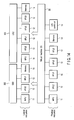
- a thread generally makes a state transition from when it is created until it is deleted. As shown in FIG. 32, a thread makes the following seven state transitions.
- a thread context is created but its contents are in the initial state.
- This transition is made by deleting a thread.
- the stored thread context is discarded by the transition.
- This transition is made when the thread requests the runtime environment to schedule the thread.
- This transition is made when an event (e.g., synchronization, communication, timer interruption) for which the thread waits is generated.
- an event e.g., synchronization, communication, timer interruption
- This transition is made when the thread is dispatched to MPU or VPU by the runtime environment.
- the thread context is loaded. When the thread context is saved, it is restored.
- This transition is made when the thread suspends its own running to wait for an event using a synchronization mechanism, a communication mechanism and the like.
- the thread in every class can be set to store its thread context.
- the thread context is saved by the runtime environment when the thread transits from RUNNING state to WAITING state.
- the saved thread context is maintained unless the thread transits to DORMANT state and restored when the thread transits to the RUNNING state.
- This transition is made when the running of the thread is forcibly suspended in response to an instruction from the runtime environment or other threads.
- the thread in every class can be set to store its thread context.
- the thread context is saved by the runtime environment when the thread transits from RUNNING state to SUSPENDED state.
- the saved thread context is maintained unless the thread transits to DORMANT state and restored when the thread transits to the RUNNING state.
- This transition is made when the thread is forced to stop by instruction from outside while it is waiting for an event to generate in the WAITING state.
- This transition is made when the thread resumes running by instruction from outside while it is in the WAITING-SUSPENDED state.
- This transition is made when the event for which the thread waits in the WAITING state is generated.
- the term of the running state of a thread to which a VPU is allocated is called an execution term.
- a term from creation to deletion of a thread includes a plurality of execution terms of the thread.
- FIG. 33 shows an example of thread states varied from creation to deletion. This example includes two execution terms during the presence of the thread.
- the thread context can be saved and restored using various methods. Most normal threads run so as to save a context at the end of an execution term and restore the context at the beginning of the next execution term. In a certain periodic operation, the thread run so as to create a new context at the beginning of an execution term, use the context during the execution term, and discard the context at the end of the execution term in every period.
- FIG. 34 shows execution terms of threads belonging to the same tightly coupled thread group. All the threads belonging to a certain tightly coupled thread group are scheduled by the VPU runtime environment 401 such that they can run at once in one execution term. This tightly coupled thread group is used chiefly for hard real-time threads. In order to achieve the operation, therefore, the VPU runtime environment 401 designates processors used at once and their number when an execution term is reserved for the hard real-time class. Moreover, the VPU runtime environment 401 makes contexts of threads running at once correspondent to the processors, respectively.
- the threads which belonged to the tightly coupled thread group in a certain execution term, can run separately from each other in other execution term by canceling their tightly coupled relationship.
- Each of the threads has to sense whether it runs as a tightly coupled thread or separately from another thread and perform an operation of communication and synchronization with its partner thread.
- Each of the threads is provided with an attribute that indicates preemptive or non-preemptive.
- the preemptive attribute permits a thread to be preempted during its execution term and, in other words, permits the thread to stop running.
- the non-preemptive attribute ensures that a thread cannot be preempted during its execution term.
- the non-preemptive attribute varies in meaning from thread class to thread class.
- the hard real-time class when a thread starts to run, nothing but the thread in itself can stop the running until its execution term ends.
- the soft real-time class preemptiveness is essential and thus the non-preemptive attribute is not supported.
- a thread In the best effort class, a thread can be protected against being preempted from another best effort class, but it can be preempted from a higher-level class such as the hard real-time class and soft real-time class.
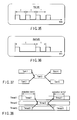
- the execution models of threads can roughly be classified into two models: a periodic execution model as shown in FIG. 35 and an aperiodic execution model as shown in FIG. 36.
- a periodic execution model a thread is executed periodically.
- a periodic running model a thread is executed based on an event.
- the periodic execution model can be implemented using a software interrupt or an event object such as synchronization primitives.
- the periodic execution model is implemented using a software interrupt.
- the VPU runtime environment 401 jumps to an entry point of a thread determined by a given method with timing to start a periodic operation or calls a callback function registered in advance by a given procedure.
- the periodic execution model is implemented using an event object.
- a soft real-time thread waits an event object in each period, and perform a given operation upon generation of the event, thereby realizing a periodic execution model.
- the periodic execution model can be implemented using either one of a software interrupt or an event object. The actual execution does not always start at the beginning of each period, but may be delayed within constraints.
- the aperiodic execution model can be realized as the periodic execution model.
- the aperiodic execution model differs from the periodic execution model only in the timing with which an event is notified and these models are the same in the implementing method.
- the minimum inter-arrival time and the dead line which are necessary for securing time requirements, strongly constrain the operation of the system; accordingly, the aperiodic execution is restricted.
- one of methods for switching a context at the end of the execution term of a VPU thread can be selected. Since the costs for switching the context are very high, the selection of one method improves the efficiency of switching. The selected method is used at the end of the reserved execution term of a thread.
- a context is switched during the execution term or at the time of preemption, all contexts of the current thread need to be saved in whatever case and restored when the thread resumes running next. For example, there are following methods of switching a VPU context.
- the context switching is delayed until all operations of the DMA controller in the memory controller in a VPU are completed. After that, the contents of the register and local storage in the VPU are saved. In this method, all the contexts of the VPU as well as the complete saving are saved.
- the scheduling of threads in the soft real-time class is performed using a fixed priority scheduling method in order to allow the running patterns of threads to be predicted.
- Two different scheduling algorithms are prepared for the scheduling method: one is fixed priority FIFO scheduling and the other is fixed priority round robin scheduling.
- the lower-priority thread is preempted and immediately the higher-priority thread starts to run.
- a synchronization mechanism such as a priority inheritance protocol and a priority ceiling protocol.
- the scheduling of threads in the best effort class is performed using dynamic priority scheduling and the like.
- the thread inter-class scheduling and thread intra-class scheduling have a hierarchical structure.
- the thread inter-class scheduling operates to determine which thread class is executed and then which thread in the thread class is executed.
- the thread inter-class scheduling employs preemptive fixed priority scheduling.
- the hard real-time class has the highest priority, with the soft real-time class and the best effort class following in that order.
- a thread in a higher-priority class is ready to run, a lowest-priority thread is preempted.
- Synchronization between thread classes is achieved by a synchronous primitive provided by the VPU runtime environment 401. In particular, only the primitive can be used in a hard real-time thread to prevent a block from occurring in the hard real-time thread.
- a best effort thread blocks a soft real-time thread, it is processed as a soft real-time thread to prevent priority from being inverted between thread classes. Furthermore, the use of, e.g., the priority inheritance protocol prevents another soft real-time thread from blocking the best effort thread.
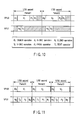
- FIG. 41 shows examples of fundamental parameters for the hard real-time class.
- example 1 to designate an execution term shown in the uppermost part of FIG. 41 one MPU and two VPUs are reserved at once in the designated execution term, and the context of each of the VPUs is completely saved.
- the threads run at the same time on the three processors and, after the execution term, the contexts of VPU threads as well as that of an MPU thread are completely saved.
- example 2 shows a method of designating a deadline to ensure that an operation represented by the number of VPUs and their execution term is performed before the deadline.
- the deadline is designated by relative time starting at the request time when a reservation request is made.
- example 3 shows a method of designating a periodic execution.
- an execution term that designates two VPUs 12 is periodically repeated, and the contexts of VPU threads are discarded after the execution term for each period, with the result that all operations are performed by new contexts.
- the deadline is designated by relative time starting at the beginning of the period.
- the timing constraints provide a unit which delays execution timing.
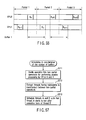
- the absolute timing constraint is a condition for designating delay time with reference to static timing, such as the start time of a period, as shown in FIG. 42.
- the relative timing constraint is a condition for designating permissible delay time with reference to dynamic timing and an event, such as the start time and end time of a certain, as shown in FIG. 43. Since the precedence constraint can be achieved by designating delay time as 0 or longer with reference to the end time of a certain execution term using the relative timing constraint, it can be considered to be a special one for the relative timing constraint.
- the mutual exclusive constraint is a condition for ensuring that execution terms do not overlap each other, as shown in FIG. 44.
- the mutual exclusive constraint makes it possible to lessen the prediction impossibility of the execution term, which is caused by a lock. In other words, all threads common to some resources are prevented from running at once to obviate a lock regarding the resources.
- the other synchronous primitives can be used.
- the real-time processing system of the present embodiment provides the following three methods to achieve the above synchronization mechanisms:
- the synchronization mechanisms are implemented on the memory (main storage) 14 or the local storage 32 of a VPU using an instruction such as a TEST & SET;
- the synchronization mechanisms are implemented using a mechanism provided as a service by the VPU runtime environment.
- a synchronization mechanism implemented using the memory (main storage MS) 14 that is shared and accessed by the MPU and VPUs can be used for threads in all classes.
- a synchronization mechanism implemented on the local storage LS of a VPU 12 can be used only for threads belonging to the tightly coupled thread group. This is because only the threads belonging to the tightly coupled thread group ensure that their partner threads for synchronization run at the same.
- the execution of the partner thread is ensured when the synchronization mechanism is used.
- the local storage of the VPU that executes the partner thread always stores information for the synchronization mechanism.
- a synchronization mechanism using a unit other than the memory (main storage MS) and local storage LS can be implemented by a hardware mechanism or a service of the VPU runtime environment 401. Since the threads belonging to the tightly coupled thread or those in the hard real-time class require a high-speed synchronization mechanism, the synchronization mechanism implemented by the hardware mechanism is desirable to use in the threads. In contrast, the synchronization mechanism provided by the runtime environment is desirable to use in the threads belonging to the loosely coupled thread group or those belonging to the soft real-time class and best effort class.
- the above synchronization mechanisms can automatically be selected or switched in accordance with the attribute and status of threads. This operation is performed by a procedure as shown in FIG. 46. While threads for synchronization belong to the tightly coupled thread group (YES in step S201), a high-speed synchronization mechanism that is implemented by the memory 14, the local storage 32 of each VPU 12 or the hardware mechanism is used (steps S202, S203, S204, S205).
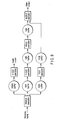
- FIG. 47 shows a reservation graph corresponding to the data flow shown in FIG. 9.
- six boxes represent execution terms.
- the upper left number on each of the boxes indicates the ID of an execution term to be reserved.
- the symbol in each box indicates the identifier of a thread context related to the execution term.
- the lower right number on each box indicates the length (cost) of the execution term.
- the arrows connecting the boxes all denote precedence constraints. In other words, an arrow extending from one box to another box indicates that an operation in the execution term of the latter box starts after an operation in that of the former box is completed. A chain of execution terms can thus be represented.
- the VPU runtime environment 401 assigns necessary resources to the program to create a thread context.
- the handle of the thread context is returned and thus referred to as an identifier.
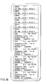
- FIG. 48 shows a reservation request containing buffer data written as BUFFER and execution term data written as TASK.
- the buffer data is used to declare a buffer on the memory 14 for data transfer between execution terms.
- Id indicates buffer number
- Size indicates buffer size
- SrcTask shows execution term number that writes data
- DstTask shows execution term number that reads data.
- execution term data “Id” represents execution term number
- Class indicates thread class (VPU shows VPU thread and HRT shows hard real-time class.
- MPU showing MPU thread
- SRT showing soft real-time class
- BST showing best effort class and so on
- ThreadContext denotes thread context corresponding to the execution term
- Cost indicates length or cost of the execution term
- Constraint represents various constraints based on the execution term
- InputBuffer shows a list of identifiers of buffers read in the execution term
- OutputBuffer indicates a list of identifiers of buffers written in the execution term.
- the “Constraint” also can include “Precedence” showing precedence constraint, “Absolute Timing” showing absolute timing constraint, “Relative Timing” showing relative timing constraint and “Exclusive” showing mutual exclusive constraint.
- the "Constraint” has a list of numbers of execution terms of partner threads for constraints.
- the buffer area reserved by the reservation request shown in FIG. 48 is allocated to the main memory 14 and released therefrom by the VPU runtime environment 401.
- the allocation of the buffer area is performed when a thread that writes data to the buffer area starts to run.
- the release of the buffer area is performed when a thread that reads data from the buffer area exits.
- the thread can be notified of the address of the allocated buffer using an address, a variable or a register that is predetermined when the thread starts to run.
- the program module 100 shown in FIG. 7 when the program module 100 shown in FIG. 7 is provided, the structural description 117 shown in FIG. 8 is read out of the program module 100 and, based on the structural description 117, a thread context is created by the above procedures and a reservation request as shown in FIG.
- a program module having a structure as shown in FIG. 7 is created for each hardware to be implemented and then executed by an apparatus having a function conforming to the real-time processing system of the present embodiment, with the result that the apparatus can be operated as desired hardware.
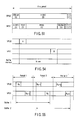
- the VPU runtime environment 401 determines which VPU 12 executes each task with which timing in a period. This is scheduling. Actually, a plurality of reservation requests can be provided at once; therefore, operation timing is determined to prevent them from contradicting each other (prevent given constraints from not being satisfied). Assuming that only the reservation request shown in FIG. 48 is made when there are two VPUs 12 as shown in FIG. 49, the scheduling is performed such that the VPU 0 sequentially performs DEMUX, V-DEC, PROG and BLEND operations which cannot be done in parallel and after the DEMUX operation, the VPU1 performs the A-DEC and TEXT operations that can be done in parallel.
- VPU 0 performs the DEMUX and V-DEC operations in the first period and the VPU 1 performs the A-DEC, TEXT, PROG and BLEND operations in the second period.
- the VPU 0 performs DEMUX and V-DEC operations in the next frame in parallel with the A-DEC, TEXT, PROG and BLEND operations.
- the pipeline processing is performed in which the VPU 1 performs the A-DEC, TEXT, PROG and BLEND operations upon receipt of outputs from the DEMUX and V-DEC operations in the preceding period while the VPU 0 is performing the DEMUX and V-DEC operations.
- FIG. 52 is a flowchart of procedures for scheduling to achieve a software pipeline operation.
- the VPU runtime environment 401 determines that the threads DEMUX, V-DEC, PROG and BLEND cannot be executed within one period (NO in step S401), it divides all the threads DEMUX, V-DEC, A-DEC, TEXT, PROG and BLEND for executing the program module 100 into two groups (referred to as first and second thread groups hereinafter) that can be executed in sequence, based on the order of execution of the threads DEMUX, V-DEC, A-DEC, TEXT, PROG and BLEND (step S402).
- the first thread group is a set of one or more threads executed before the second thread group
- the second thread group is a set of one or more threads executed after the first thread group.
- the threads DEMUX and V-DEC belong to the first thread group and the threads A-DEC, TEXT, PROG and BLEND belong to the second thread group to satisfy the precedence constraints between the threads and make the total execution term of each of the groups not longer than the time interval corresponding to one period.
- the VPU runtime environment 401 performs the scheduling operation to periodically assigns the execution term of each of the threads belonging to the first thread group (DEMUX and V-DEC) to the VPU0 such that the VPU0 executes the first thread group periodically at time intervals of 1/60 second (step S403).
- step S403 periodic execution of each of the threads DEMUX and V-DEC is reserved for the VPU0.
- Two processors VPU0 and VPU1 execute the first thread group (DEMUX and V-DEC) and the second thread group (A-DEC, TEXT, PROG and BLEND) in pipeline mode. Consequently, the first thread group and the second thread group are executed in parallel while the second thread group is delayed one period relative to the first thread group, thus outputting frame data processing results for each period of 1/60 second.
- a buffer When a buffer is used to transfer data between a thread running in an execution term and a thread running in another execution term, the buffer is occupied from the beginning of the execution term on the data write side to the end of the execution term on the data read side.
- a buffer on the memory 14 main storage
- it is occupied from the beginning of execution term A to the end of execution term B. Therefore, when a buffer is used to transfer data from execution term A to execution term B and the execution terms A and B belong to their respective periods adjacent to each other in software pipeline processing, the number of buffers required varies according to the execution timing in the execution terms A and B. For example, as shown in FIG.
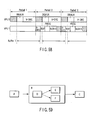
- the scheduler in the VPU runtime environment 401 schedules execution terms to be reserved such that the amount of use of buffer memory areas becomes as small as possible. More specifically, in order to execute software pipeline processing of two VPUs 0 and 1, the scheduler in the VPU runtime environment 401 divides an operation into two partial operations (one to be performed first by the VPU 0 and the other to be performed next by the VPU 1) as shown in the flowchart in FIG. 57 (step S211). Then, the scheduler extracts threads (thread A in the partial operation to be performed first and thread B in the partial operation to be performed next) which inputs/outputs data through a buffer between the two VPUs (step S212). The threads A and B are scheduled such that the thread A starts to run after the end of the execution term for the thread B in each period (step S213).
- the execution term of the thread B can thus be interposed between the two execution terms of the thread A corresponding to consecutive two periods.
- FIG. 58 shows a specific example of scheduling performed in consideration of the number of buffers.
- the thread DEMUX in the first thread group is a thread for writing to a buffer data to be transferred to the A-DEC in the second thread group.
- the execution start timing of each of the threads A-DEC and DEMUX is controlled such that the thread DEMUX starts to run after the thread A-DEC completes running in each period.
- the VPU runtime environment 401 reserves a buffer area 1 on the memory 14 when the thread DEMUX starts to run in period 1 and releases it when the thread A-DEC completes running in the next period 2. Then, the VPU runtime environment 401 reserves the buffer area 1 on the memory 14 when the thread DEMUX starts to run in period 2 and releases it when the thread A-DEC completes running in the next period 3.
- FIG. 47 has no hierarchical structure
- a reservation graph having a hierarchical structure can be used as shown in FIG. 59.
- the execution term A precedes the execution term B and the execution term B precedes the execution term C.
- the execution term D precedes execution terms E and F. Resolving the hierarchy, the execution term A precedes the execution term D and the execution terms E and F precede the execution term C.
- FIG. 8 shows an example of the structural description 117 incorporated in the program module 100 shown in FIG. 7.
- the VPU runtime environment 401 performs the following steps.
- BUFFER records are created to correspond to the output fields of the structural description 117 in a one-to-one basis and added to the reservation request. For instance, in the example of FIG. 8, the second output data of the DEMUX module is supplied to the V-DEC through the 1-MB buffer, so that a BUFFER record whose Id is 2 as shown in FIG. 48 is created.
- the buffer size is described as 1MB in Size field
- reference to TASK record whose Id is 1 and which corresponds to a DEMUX module that writes data to the buffer is described in SrcTask field
- reference to TASK record whose Id is 3 and which corresponds to a V-DEC module that reads data from the buffer is described in DstTask field.
- TASK records are created to correspond to the module fields of the structural description 117 on a one-to-one basis and added to the reservation request. For instance, in the example of FIG. 8, a TASK record whose Id is 3 as shown in FIG. 48 is created as one corresponding to the V-DEC module. This TASK record has the following information.
- Class field Flag to indicate what attribute is used to execute a thread designated in the TASK record.
- VPU represents a thread that runs on the VPU and "HRT” shows a thread in the hard-real time class.
- ThreadContext field Flag to designate a thread context of a thread whose running is to be reserved in the TASK record. More specifically, a program module designated in the module field of the structural description 117 is loaded, a thread that executes the program module is generated by the VPU runtime environment 401, and an identifier (a pointer or the like) of the thread context of the thread is recorded in the "ThreadContext" field.
- Constraint field Flag to record constraints of the TASK record.
- a required number of Ids of another TASK record preceded by the TASK record is designated after the "Precede" field. For example, a TASK record whose Id is 3 precedes a TASK record corresponding to the PROG module whose Id is 5.
- InputBuffer field Flag to designate a required number of Ids of the Buffer record of a buffer from which data is read by the thread designated by the TASK record.
- OutputBuffer field Flag to designate a required number of Ids of the Buffer record of a buffer to which data is written by the thread designated by the TASK record.
- the scheduler When the reservation request is sent to the scheduler in the VPU runtime environment 401, the scheduler creates a schedule necessary for performing the reservation request.
- This schedule represents which VPU is allocated to which thread with which timing and how long the VPU is allocated in a period as shown in FIG. 49.
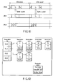
- the schedule can be represented by a reservation list as shown in FIG. 62.
- the reservation list shown in FIG. 62 includes reservation entries related to the respective VPUs.
- Each of the reservation entries includes a start time field indicating when a thread is executed by VPU in each period (execution start timing of the thread), an execution term field indicating how long the VPU is allocated to the thread (execution term of the thread), and a running thread field indicating an identifier of the thread.
- the reservation entries are sorted in order of start time according to the VPUs and linked to the reservation list.
- the procedure for creating a reservation list as shown in FIG. 62 from the reservation request shown in FIG. 48 or FIG. 60 can be carried out by the flowchart shown in FIG. 63.
- the TASK records in the reservation request have only to be sequenced in consideration of the relationship in input/output using BUFFER and the running time of VPUs has only to be assigned to each of the TASK records in the order of data flow. It is then necessary to simultaneously allocate the VPUs to the Tasks belonging to the tightly coupled thread group.
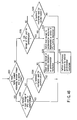
- the VPU runtime environment 401 schedules all the tasks designated by TASK records in the reservation request by the following steps (in other words, the VPU runtime environment 401 creates a reservation list for reserving a VPU to which each task is assigned and the execution start timing and execution term of the task).
- Step S301 The VPU runtime environment 401 selects a task whose all of preceding tasks (input tasks) have been already scheduled, and which have no tightly coupled attributes, from among tasks that are not scheduled. If a task is preceded by no input tasks, it is determined as one whose input tasks have been already scheduled.
- the VPU runtime environment 401 selects it and moves to step S302. If not, it moves to step S304.
- Step S302 If there is a VPU that can assign the execution start timing and execution term of the selected task under satisfactory constraints, the VPU runtime environment 401 moves to step S303. If not, the VPU runtime environment 401 fails in the scheduling and makes a notification of the fail.
- Step S303 The VPU runtime environment 401 creates reservation entries of the selected task and links them to the reservation list.
- Step S304 The VPU runtime environment 401 selects tasks whose all input tasks have been already scheduled, and that belong to a tightly coupled group, from among tasks that are not scheduled. If tasks are preceded by no input tasks, they are determined as ones whose input tasks have been already scheduled.
- Step S305 If there are VPUs that can reserve all tasks included in the selected tasks at once (to have the same execution start timing and the same execution term), the VPU runtime environment 401 moves to step S306. If not, the VPU runtime environment 401 fails in the scheduling and makes a notification of the fail.
- Step S306 Reservation entries of all tasks of the selected set of tasks are created and linked to the reservation list.
- the present embodiment has been described taking the program module describing the operations of a digital TV broadcast receiver as an example. If, however, a program module describing the operations of various types of hardware is prepared, the operations of hardware can be performed by software.
- the MPU 11 and VPUs 12 provided in the computer system shown in FIG. 1 can be implemented as parallel processor mixed on one chip.
- the VPU running environment executed by the MPU 11 or the VPU running environment executed by a specific VPU or the like can control scheduling for the VPUs 12.
- the software pipeline operation can be performed by three VPUs.
- a plurality of chained tasks for performing a real-time operation are divided into first to three task groups to be processed in sequence.
- Each of the task groups is periodically assigned to at least one of the VPUs such that the three VPUs periodically execute the three task groups in pipeline mode. If VPU1, VPU2 and VPU3 are used, the VPU0 periodically executes the first task group, the VPU1 periodically executes the second task group with a one-period delay relative to the first task group, and the VPU2 periodically executes the third task group with a one-period delay relative to the second task group.
- a plurality of VPUs can execute the tasks of a task group in parallel. If a task group includes a plurality of tasks that can run in parallel, a plurality of VPUs can execute the tasks of the task group in parallel.
- the programs running as the VPU running environment or the programs of the operating system including the VPU running environment are stored in a computer readable storage medium and then introduced and executed in a computer including a plurality of processors each having a local memory, the same advantages as those of the foregoing embodiment of the present invention can be obtained.
Landscapes
- Engineering & Computer Science (AREA)
- Software Systems (AREA)
- Theoretical Computer Science (AREA)
- Physics & Mathematics (AREA)
- General Engineering & Computer Science (AREA)
- General Physics & Mathematics (AREA)
- Multi Processors (AREA)
- Debugging And Monitoring (AREA)
Applications Claiming Priority (2)
| Application Number | Priority Date | Filing Date | Title |
|---|---|---|---|
| JP2003199943A JP3920818B2 (ja) | 2003-07-22 | 2003-07-22 | スケジューリング方法および情報処理システム |
| JP2003199943 | 2003-07-22 |
Publications (2)
| Publication Number | Publication Date |
|---|---|
| EP1501013A2 true EP1501013A2 (de) | 2005-01-26 |
| EP1501013A3 EP1501013A3 (de) | 2006-07-26 |
Family
ID=33487627
Family Applications (1)
| Application Number | Title | Priority Date | Filing Date |
|---|---|---|---|
| EP04015759A Withdrawn EP1501013A3 (de) | 2003-07-22 | 2004-07-05 | System und Verfahren zur Echtzeit periodischen Aufgabenablaufsteuerung |
Country Status (5)
| Country | Link |
|---|---|
| US (1) | US8495651B2 (de) |
| EP (1) | EP1501013A3 (de) |
| JP (1) | JP3920818B2 (de) |
| KR (1) | KR100649107B1 (de) |
| CN (1) | CN1287282C (de) |
Cited By (7)
| Publication number | Priority date | Publication date | Assignee | Title |
|---|---|---|---|---|
| WO2006129285A1 (en) * | 2005-06-03 | 2006-12-07 | Nxp B.V. | Data processing system and method for scheduling the use of at least one exclusive resource |
| WO2009029549A3 (en) * | 2007-08-24 | 2009-04-16 | Virtualmetrix Inc | Method and apparatus for fine grain performance management of computer systems |
| EP1939726A4 (de) * | 2005-09-26 | 2009-06-24 | Netac Technology Co Ltd | Verfahren zur multitask-realisierung in einer media-wiedergabeeinrichtung |
| US8677071B2 (en) | 2010-03-26 | 2014-03-18 | Virtualmetrix, Inc. | Control of processor cache memory occupancy |
| US8782653B2 (en) | 2010-03-26 | 2014-07-15 | Virtualmetrix, Inc. | Fine grain performance resource management of computer systems |
| WO2018024581A1 (fr) * | 2016-08-04 | 2018-02-08 | Thales | Procede et dispositif de distribution de partitions sur un processeur multi-coeurs |
| US11563621B2 (en) | 2006-06-13 | 2023-01-24 | Advanced Cluster Systems, Inc. | Cluster computing |
Families Citing this family (55)
| Publication number | Priority date | Publication date | Assignee | Title |
|---|---|---|---|---|
| JP3889726B2 (ja) * | 2003-06-27 | 2007-03-07 | 株式会社東芝 | スケジューリング方法および情報処理システム |
| JP4025260B2 (ja) | 2003-08-14 | 2007-12-19 | 株式会社東芝 | スケジューリング方法および情報処理システム |
| JP4197673B2 (ja) * | 2004-09-30 | 2008-12-17 | 株式会社東芝 | マルチプロセッサ計算機及びタスク実行方法 |
| JP4197672B2 (ja) * | 2004-09-30 | 2008-12-17 | 株式会社東芝 | マルチプロセッサ計算機及びプログラム |
| US20060136916A1 (en) * | 2004-12-17 | 2006-06-22 | Rowland John R | Method and apparatus for transaction performance and availability management based on program component monitor plugins and transaction performance monitors |
| CN100442239C (zh) * | 2007-01-09 | 2008-12-10 | 上海新时达电气有限公司 | 中断程序的分时运行方法 |
| CN102057357A (zh) * | 2008-06-11 | 2011-05-11 | 松下电器产业株式会社 | 多处理器系统 |
| JP2009301500A (ja) * | 2008-06-17 | 2009-12-24 | Nec Electronics Corp | タスク処理システム及びタスク処理方法 |
| KR101513505B1 (ko) | 2008-11-04 | 2015-04-20 | 삼성전자주식회사 | 프로세서 및 인터럽트 처리 방법 |
| KR101622168B1 (ko) * | 2008-12-18 | 2016-05-18 | 삼성전자주식회사 | 실시간 스케쥴링 방법 및 이를 이용한 중앙처리장치 |
| KR101085229B1 (ko) * | 2009-08-20 | 2011-11-21 | 한양대학교 산학협력단 | 멀티 코어 시스템 및 멀티 코어 시스템의 태스크 할당 방법 |
| FI123008B (fi) * | 2010-06-22 | 2012-09-28 | Janne Pitkaenen | Laitteisto ja menetelmä käytettävyystestausta varten |
| JP5585651B2 (ja) * | 2010-06-29 | 2014-09-10 | 富士通株式会社 | マルチコアシステム、スケジューリング方法およびスケジューリングプログラム |
| WO2012001835A1 (ja) | 2010-07-02 | 2012-01-05 | パナソニック株式会社 | マルチプロセッサシステム |
| US8832700B2 (en) * | 2010-09-29 | 2014-09-09 | Microsoft Corporation | Subscriber-based ticking model for platforms |
| CN102467415B (zh) * | 2010-11-03 | 2013-11-20 | 大唐移动通信设备有限公司 | 一种业务面任务处理方法及设备 |
| JP2012252413A (ja) * | 2011-05-31 | 2012-12-20 | Toshiba Corp | 情報処理装置、情報処理方法及び制御プログラム |
| CN103597416A (zh) * | 2011-06-09 | 2014-02-19 | 三菱电机株式会社 | 可编程控制器系统 |
| US10956485B2 (en) | 2011-08-31 | 2021-03-23 | Google Llc | Retargeting in a search environment |
| US10630751B2 (en) * | 2016-12-30 | 2020-04-21 | Google Llc | Sequence dependent data message consolidation in a voice activated computer network environment |
| US9355009B2 (en) | 2011-10-31 | 2016-05-31 | International Business Machines Corporation | Performance of scheduled tasks via behavior analysis and dynamic optimization |
| US9047396B2 (en) | 2011-10-31 | 2015-06-02 | International Business Machines Corporation | Method, system and computer product for rescheduling processing of set of work items based on historical trend of execution time |
| US8904397B2 (en) | 2011-10-31 | 2014-12-02 | International Business Machines Corporation | Staggering execution of scheduled tasks based on behavioral information |
| CN102393822B (zh) * | 2011-11-30 | 2014-03-12 | 中国工商银行股份有限公司 | 批量调度系统及方法 |
| JP5820525B2 (ja) * | 2012-03-29 | 2015-11-24 | 株式会社日立製作所 | 仮想計算機のスケジュールシステム及びその方法 |
| US9594703B2 (en) * | 2012-03-29 | 2017-03-14 | Intel Corporation | Architecture and method for managing interrupts in a virtualized environment |
| US9766931B2 (en) * | 2012-04-30 | 2017-09-19 | Massachusetts Institute Of Technology | Uniprocessor schedulability testing for non-preemptive task sets |
| JP5801331B2 (ja) * | 2012-06-28 | 2015-10-28 | 株式会社Nttドコモ | タスク制御装置 |
| WO2014022968A1 (zh) * | 2012-08-07 | 2014-02-13 | 华为技术有限公司 | 媒体业务处理方法及媒体业务系统 |
| US10802876B2 (en) * | 2013-05-22 | 2020-10-13 | Massachusetts Institute Of Technology | Multiprocessor scheduling policy with deadline constraint for determining multi-agent schedule for a plurality of agents |
| US9703757B2 (en) | 2013-09-30 | 2017-07-11 | Google Inc. | Automatically determining a size for a content item for a web page |
| US10431209B2 (en) | 2016-12-30 | 2019-10-01 | Google Llc | Feedback controller for data transmissions |
| US10614153B2 (en) | 2013-09-30 | 2020-04-07 | Google Llc | Resource size-based content item selection |
| CN104699533B (zh) * | 2013-12-09 | 2017-11-28 | 中国航空工业集团公司第六三一研究所 | 一种多个周期任务的调度方法 |
| CN104980330B (zh) * | 2014-04-08 | 2018-06-19 | 中国科学院软件研究所 | 一种实时多智能体系统的消息准入方法 |
| US9424102B2 (en) * | 2014-05-14 | 2016-08-23 | International Business Machines Corporation | Task grouping by context |
| US9652305B2 (en) * | 2014-08-06 | 2017-05-16 | Advanced Micro Devices, Inc. | Tracking source availability for instructions in a scheduler instruction queue |
| JP6432450B2 (ja) | 2015-06-04 | 2018-12-05 | 富士通株式会社 | 並列計算装置、コンパイル装置、並列処理方法、コンパイル方法、並列処理プログラムおよびコンパイルプログラム |
| KR102235166B1 (ko) | 2015-09-21 | 2021-04-02 | 주식회사 레인보우로보틱스 | 실시간 로봇 시스템, 로봇 시스템 제어 장치 및 로봇 시스템 제어 방법 |
| CN105320570B (zh) | 2015-11-09 | 2019-01-29 | 深圳市万普拉斯科技有限公司 | 资源管理方法和系统 |
| CN105320561B (zh) * | 2015-11-09 | 2019-03-08 | 深圳市万普拉斯科技有限公司 | 任务管理方法和系统 |
| CN105700943A (zh) * | 2015-12-31 | 2016-06-22 | 上海百事通信息技术股份有限公司 | 分布式任务调度方法及系统 |
| CN107544817B (zh) * | 2016-06-28 | 2021-11-02 | 中兴通讯股份有限公司 | 一种控制应用程序的方法及装置 |
| CN107885585A (zh) * | 2016-09-30 | 2018-04-06 | 罗伯特·博世有限公司 | 一种在多核电子控制单元中的动态任务调度器 |
| KR102309429B1 (ko) * | 2017-03-20 | 2021-10-07 | 현대자동차주식회사 | 차량 및 그 제어 방법 |
| CN110413419A (zh) * | 2018-04-28 | 2019-11-05 | 北京京东尚科信息技术有限公司 | 一种规则执行的方法和装置 |
| CN112912849B (zh) | 2018-07-27 | 2024-08-13 | 浙江天猫技术有限公司 | 一种基于图数据的计算运行调度方法、系统、计算机可读介质及设备 |
| KR102184136B1 (ko) * | 2019-05-08 | 2020-11-27 | 국방과학연구소 | 계층적 스케줄링 시스템에서 자원 공급 모델의 주기를 결정하는 방법 및 장치 |
| CN110162392B (zh) * | 2019-05-29 | 2022-10-25 | 北京达佳互联信息技术有限公司 | 周期性任务的执行方法、装置、电子设备及存储介质 |
| KR102287318B1 (ko) * | 2019-11-15 | 2021-08-09 | 현대자동차주식회사 | 오토사 기반 러너블 동기화 장치 및 그 방법 |
| JP7428508B2 (ja) * | 2019-11-29 | 2024-02-06 | 日立Astemo株式会社 | 情報処理装置 |
| KR102349107B1 (ko) * | 2020-07-20 | 2022-01-07 | 현대오토에버 주식회사 | 오토사 플랫폼에서 러너블 실행을 관리하는 방법 |
| CN112256409B (zh) * | 2020-09-15 | 2022-03-04 | 中科驭数(北京)科技有限公司 | 基于多个数据库加速器的任务执行方法及装置 |
| CN114138433B (zh) * | 2021-11-18 | 2024-01-12 | 苏州浪潮智能科技有限公司 | 一种任务定时策略的方法、装置及介质 |
| US12135970B2 (en) * | 2023-03-17 | 2024-11-05 | The Boeing Company | System and method for synchronizing processing between a plurality of processors |
Family Cites Families (13)
| Publication number | Priority date | Publication date | Assignee | Title |
|---|---|---|---|---|
| JPH06242967A (ja) | 1993-02-16 | 1994-09-02 | Mitsubishi Electric Corp | バッファ操作方法及びバッファ管理装置 |
| JP3193525B2 (ja) | 1993-05-31 | 2001-07-30 | キヤノン株式会社 | 情報処理装置 |
| CA2131406C (en) * | 1993-09-21 | 2002-11-12 | David D'souza | Preemptive multi-tasking with cooperative groups of tasks |
| WO1996003690A1 (en) * | 1994-07-22 | 1996-02-08 | Debenedictis Erik P | Method and apparatus for controlling connected computers without programming |
| JPH08180025A (ja) | 1994-12-21 | 1996-07-12 | Toshiba Corp | スケジューリング装置 |
| US6012080A (en) * | 1996-03-27 | 2000-01-04 | Lucent Technologies Inc. | Method and apparatus for providing enhanced pay per view in a video server |
| US7116635B2 (en) * | 1996-03-28 | 2006-10-03 | Hitachi, Ltd. | Process execution method and apparatus |
| JPH10143380A (ja) | 1996-11-07 | 1998-05-29 | Hitachi Ltd | マルチプロセッサシステム |
| US6035333A (en) * | 1997-11-24 | 2000-03-07 | International Business Machines Corporation | Method and system for providing congestion control in a data communications network |
| CA2245976A1 (en) * | 1998-08-26 | 2000-02-26 | Qnx Software Systems Ltd. | Symmetric multi-processor system and method |
| US6430694B1 (en) | 1998-12-31 | 2002-08-06 | At&T Corp. | Method and apparatus for synchronizing the provision of data among geographically distributed databases |
| CA2365729A1 (en) * | 2001-12-20 | 2003-06-20 | Platform Computing (Barbados) Inc. | Topology aware scheduling for a multiprocessor system |
| US7653906B2 (en) * | 2002-10-23 | 2010-01-26 | Intel Corporation | Apparatus and method for reducing power consumption on simultaneous multi-threading systems |
-
2003
- 2003-07-22 JP JP2003199943A patent/JP3920818B2/ja not_active Expired - Fee Related
-
2004
- 2004-07-05 EP EP04015759A patent/EP1501013A3/de not_active Withdrawn
- 2004-07-13 KR KR1020040054505A patent/KR100649107B1/ko not_active Expired - Fee Related
- 2004-07-21 US US10/895,040 patent/US8495651B2/en not_active Expired - Fee Related
- 2004-07-22 CN CNB2004100544558A patent/CN1287282C/zh not_active Expired - Fee Related
Cited By (14)
| Publication number | Priority date | Publication date | Assignee | Title |
|---|---|---|---|---|
| CN101189580B (zh) * | 2005-06-03 | 2010-05-19 | Nxp股份有限公司 | 对至少一个独占资源的使用进行调度的数据处理系统和方法 |
| US20100262969A1 (en) * | 2005-06-03 | 2010-10-14 | Nxp B.V. | Data processing system and method for scheduling the use of at least one exclusive resource |
| WO2006129285A1 (en) * | 2005-06-03 | 2006-12-07 | Nxp B.V. | Data processing system and method for scheduling the use of at least one exclusive resource |
| EP1939726A4 (de) * | 2005-09-26 | 2009-06-24 | Netac Technology Co Ltd | Verfahren zur multitask-realisierung in einer media-wiedergabeeinrichtung |
| US11563621B2 (en) | 2006-06-13 | 2023-01-24 | Advanced Cluster Systems, Inc. | Cluster computing |
| US12021679B1 (en) | 2006-06-13 | 2024-06-25 | Advanced Cluster Systems, Inc. | Cluster computing |
| US11811582B2 (en) | 2006-06-13 | 2023-11-07 | Advanced Cluster Systems, Inc. | Cluster computing |
| US11570034B2 (en) | 2006-06-13 | 2023-01-31 | Advanced Cluster Systems, Inc. | Cluster computing |
| WO2009029549A3 (en) * | 2007-08-24 | 2009-04-16 | Virtualmetrix Inc | Method and apparatus for fine grain performance management of computer systems |
| US8397236B2 (en) | 2007-08-24 | 2013-03-12 | Virtualmetrix, Inc. | Credit based performance managment of computer systems |
| US8677071B2 (en) | 2010-03-26 | 2014-03-18 | Virtualmetrix, Inc. | Control of processor cache memory occupancy |
| US8782653B2 (en) | 2010-03-26 | 2014-07-15 | Virtualmetrix, Inc. | Fine grain performance resource management of computer systems |
| US11175963B2 (en) | 2016-08-04 | 2021-11-16 | Thales | Method and device for distributing partitions on a multicore processor |
| WO2018024581A1 (fr) * | 2016-08-04 | 2018-02-08 | Thales | Procede et dispositif de distribution de partitions sur un processeur multi-coeurs |
Also Published As
| Publication number | Publication date |
|---|---|
| EP1501013A3 (de) | 2006-07-26 |
| JP2005043959A (ja) | 2005-02-17 |
| US8495651B2 (en) | 2013-07-23 |
| US20050060709A1 (en) | 2005-03-17 |
| JP3920818B2 (ja) | 2007-05-30 |
| CN1287282C (zh) | 2006-11-29 |
| CN1577278A (zh) | 2005-02-09 |
| KR20050011689A (ko) | 2005-01-29 |
| KR100649107B1 (ko) | 2006-11-24 |
Similar Documents
| Publication | Publication Date | Title |
|---|---|---|
| US8495651B2 (en) | Method and system for performing real-time operation including plural chained tasks using plural processors | |
| US7657890B2 (en) | Scheduling system and method in which threads for performing a real-time operation are assigned to a plurality of processors | |
| US7464379B2 (en) | Method and system for performing real-time operation | |
| US7685599B2 (en) | Method and system for performing real-time operation | |
| US8171477B2 (en) | Method and system for performing real-time operation | |
| US7356666B2 (en) | Local memory management system with plural processors |
Legal Events
| Date | Code | Title | Description |
|---|---|---|---|
| PUAI | Public reference made under article 153(3) epc to a published international application that has entered the european phase |
Free format text: ORIGINAL CODE: 0009012 |
|
| 17P | Request for examination filed |
Effective date: 20040705 |
|
| AK | Designated contracting states |
Kind code of ref document: A2 Designated state(s): AT BE BG CH CY CZ DE DK EE ES FI FR GB GR HU IE IT LI LU MC NL PL PT RO SE SI SK TR |
|
| AX | Request for extension of the european patent |
Extension state: AL HR LT LV MK |
|
| PUAL | Search report despatched |
Free format text: ORIGINAL CODE: 0009013 |
|
| AK | Designated contracting states |
Kind code of ref document: A3 Designated state(s): AT BE BG CH CY CZ DE DK EE ES FI FR GB GR HU IE IT LI LU MC NL PL PT RO SE SI SK TR |
|
| AX | Request for extension of the european patent |
Extension state: AL HR LT LV MK |
|
| 17Q | First examination report despatched |
Effective date: 20061016 |
|
| AKX | Designation fees paid |
Designated state(s): DE FR GB |
|
| STAA | Information on the status of an ep patent application or granted ep patent |
Free format text: STATUS: THE APPLICATION IS DEEMED TO BE WITHDRAWN |
|
| 18D | Application deemed to be withdrawn |
Effective date: 20090317 |