EP1500896A2 - Elément de couplage pour échangeur de chaleur - Google Patents
Elément de couplage pour échangeur de chaleur Download PDFInfo
- Publication number
- EP1500896A2 EP1500896A2 EP04388051A EP04388051A EP1500896A2 EP 1500896 A2 EP1500896 A2 EP 1500896A2 EP 04388051 A EP04388051 A EP 04388051A EP 04388051 A EP04388051 A EP 04388051A EP 1500896 A2 EP1500896 A2 EP 1500896A2
- Authority
- EP
- European Patent Office
- Prior art keywords
- heat
- liquid
- coupling element
- flow
- emitting
- Prior art date
- Legal status (The legal status is an assumption and is not a legal conclusion. Google has not performed a legal analysis and makes no representation as to the accuracy of the status listed.)
- Withdrawn
Links
Images


Classifications
-
- F—MECHANICAL ENGINEERING; LIGHTING; HEATING; WEAPONS; BLASTING
- F28—HEAT EXCHANGE IN GENERAL
- F28F—DETAILS OF HEAT-EXCHANGE AND HEAT-TRANSFER APPARATUS, OF GENERAL APPLICATION
- F28F9/00—Casings; Header boxes; Auxiliary supports for elements; Auxiliary members within casings
- F28F9/26—Arrangements for connecting different sections of heat-exchange elements, e.g. of radiators
-
- F—MECHANICAL ENGINEERING; LIGHTING; HEATING; WEAPONS; BLASTING
- F28—HEAT EXCHANGE IN GENERAL
- F28D—HEAT-EXCHANGE APPARATUS, NOT PROVIDED FOR IN ANOTHER SUBCLASS, IN WHICH THE HEAT-EXCHANGE MEDIA DO NOT COME INTO DIRECT CONTACT
- F28D9/00—Heat-exchange apparatus having stationary plate-like or laminated conduit assemblies for both heat-exchange media, the media being in contact with different sides of a conduit wall
- F28D9/0031—Heat-exchange apparatus having stationary plate-like or laminated conduit assemblies for both heat-exchange media, the media being in contact with different sides of a conduit wall the conduits for one heat-exchange medium being formed by paired plates touching each other
- F28D9/0043—Heat-exchange apparatus having stationary plate-like or laminated conduit assemblies for both heat-exchange media, the media being in contact with different sides of a conduit wall the conduits for one heat-exchange medium being formed by paired plates touching each other the plates having openings therein for circulation of at least one heat-exchange medium from one conduit to another
- F28D9/005—Heat-exchange apparatus having stationary plate-like or laminated conduit assemblies for both heat-exchange media, the media being in contact with different sides of a conduit wall the conduits for one heat-exchange medium being formed by paired plates touching each other the plates having openings therein for circulation of at least one heat-exchange medium from one conduit to another the plates having openings therein for both heat-exchange media
-
- F—MECHANICAL ENGINEERING; LIGHTING; HEATING; WEAPONS; BLASTING
- F28—HEAT EXCHANGE IN GENERAL
- F28F—DETAILS OF HEAT-EXCHANGE AND HEAT-TRANSFER APPARATUS, OF GENERAL APPLICATION
- F28F9/00—Casings; Header boxes; Auxiliary supports for elements; Auxiliary members within casings
- F28F9/02—Header boxes; End plates
- F28F9/0246—Arrangements for connecting header boxes with flow lines
- F28F9/0251—Massive connectors, e.g. blocks; Plate-like connectors
- F28F9/0253—Massive connectors, e.g. blocks; Plate-like connectors with multiple channels, e.g. with combined inflow and outflow channels
Definitions
- the present invention relates to a plate water heater, comprising a coupling element and a plurality of heat exchanger plates combined to a stack of plates and configured in such a manner that, between adjoining heat exchanger plates, separate flow passages are formed for conveying a heat-emitting liquid and a heat-absorbing liquid, respectively, said coupling element comprising flow channels for conveying liquid between the flow passages and the couplings and regulator means for regulating the flow of liquid in the heat-emitting liquid.
- a plate water heater typically comprises a plate heat exchanger, at least one regulator valve with one or more sensors and couplings for heat-emitting liquid, typically water from central heating plants, couplings for heat-absorbing liquid, typically utility water or liquid medium in a central heating plant.
- the plate heat exchanger comprises a primary circuit and a secondary circuit formed by a plurality of heat exchanger plates being configured in such a manner that separate flow passages are provided between adjoining heat exchanger plates for a heat-emitting liquid in the primary circuit and for a heat-absorbing liquid in the secondary circuit, respectively.
- Plate heat exchangers lend themselves for use in connection with central heating plants and typically within the context of central heating plants for small units such as eg one-family houses, villas, flats, where it serves either as plate water heater for heating the utility water, or as plate water heaters for heating a liquid medium used in the central heating system of that unit.
- plate water heaters are used in a context where it is desired to have a central heating installation with a water heater having limited outer dimensions compared to a conventional water heater that often features a receptacle volume of about 100-200 litres of utility water.
- a plate water heater is used for heating utility water
- cold utility water is conveyed into the secondary circuit of the plate heat exchanger.
- hot central heating water is conveyed that emits the heat contained therein by heat transmission to the cold utility water in the secondary circuit, whereby the utility water is heated.
- Plate heat exchangers are known from eg patent No. EP 120 319. Such plate heat exchanger has couplings for supply and discharge of liquid at the corners of an end plate, onto which couplings conduits, valves and other equipment are coupled.
- WO 99/54665 teaches a through-flow water heater with a sophisticated coupling element composed of a number of plate parts with flow channels in several layers.
- the coupling element is of a rather sophisticated construction.
- the regulation of temperature of the heat-absorbing liquid ie most often the utility water
- control is primarily exercised to maintain the desired temperature in the plate water heater ⁇ also designated "regulation without charge”. Owing to the particular configuration of the plate water heater according to the prior art, quite a large amount of heat-emitting liquid is circulated in the primary circuit.
- a plate water heater with a coupling element is accomplished wherein a heat transmission occurs from the liquid in the flow channel for supply of heat-emitting liquid to the flow channel for the heat-absorbing liquid already.
- the temperature of the heat-absorbing liquid in the flow channel for conveyance of the heat-absorbing liquid is elevated more quickly and simultaneously reaches a desired value already before the temperature of the remainder on the plate heat exchanger has reached the same level. Moreover, there is no need for conveying a quite large amount of heat-emitting liquid through the primary circuit (flow channels/flow passages for the heat-emitting liquid) to maintain a desired temperature level in the secondary circuit (flow channels/flow passages for the heat-absorbing liquid).
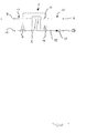
- Figure 1 shows a flow chart of a plate water heater 1 comprising a plate heat exchanger 2 with a primary circuit 13 for heat-emitting liquid and a secondary circuit 14 for heat-absorbing liquid.
- the primary circuit 13 comprises a coupling for supply 9 and a coupling for discharge 10, respectively, of heat-emitting liquid and is configured with regulator means 6 (regulator valve) 6 at the coupling for discharge 10.
- the regulator means 6 comprises a temperature sensor 11 configured for registering the temperature at the coupling for discharge 8 of liquid in the secondary circuit 14 and will, when the temperature in the secondary circuit 14 has dropped to a pre-set level, open to allow through-flow of liquid in the primary circuit 13 in order to thereby increase the temperature in the secondary circuit 14 to the pre-set level.
- the secondary circuit 14 comprises a coupling for supply 7 and a coupling for discharge 8 of heat-absorbing liquid. Moreover, on the secondary circuit 14, a safety valve 16, a further coupling 16 for establishing liquid circulation and a non-return valve 15 are provided.
- the plate water heater is shown coupled in such a manner that the liquid is conveyed counter-currently through the plate heat exchanger ⁇ ie in such a manner that, when the liquid flows through the plate heat exchanger ⁇ there is the largest possible temperature potential between the liquid in the primary circuit and the liquid in the secondary circuit.
- FIG. 2a shows a plate water heater 1 according to the invention.
- the plate water heater 1 comprises a plate heat exchanger 2, couplings for heat-emitting liquid 9, 10 and couplings for heat-absorbing liquid 7, 8, regulator means 6 (regulator valve) with a sensor 11 configured for registering the temperature in the heat-absorbing liquid in the secondary circuit 14.
- the plate heat exchanger 2 comprises a plurality of heat exchanger plates (not shown) that combine to form a plate stack 2a and are configured in such a manner that, between adjoining heat exchanger plates, separate flow passages are formed for a heat-emitting liquid in a primary circuit 13 and for a heat-absorbing liquid in a secondary circuit 14, respectively.
- the plate water heater 1 also comprises a coupling element 3 connected on the stack of heat exchanger plates in such a manner that each of the flow channels 21, 22, 23, 24, configured in the coupling element is in liquid contact with a channel opening 25, 26, 27, 28 configured in a lateral face 4 of the plate heat exchanger 2.
- the coupling element 3 is configured with the couplings 7, 8, 9 configured at a first edge of the coupling element 3 and a coupling 10a configured at a second edge of the coupling element 3.
- On the coupling 10a are shown coupled regulator means 6 with a tubular connection taken down in level with the couplings 7, 8, 9 configured at the first edge.
- a cold heat-absorbing liquid is conveyed into the coupling 7 and via the flow passage 23 in the coupling element further through the channel opening 25 into the flow passages of the secondary circuit in the in plate heat exchanger 2.
- the now heated liquid is conveyed out via the channel opening 26 through the flow channel 21 in the coupling element, in which flow channel the sensor 11 for registration of the temperature of the liquid is configured.
- the flow channel 21 is moreover connected to the coupling 8 at the first edge of the coupling element.
- heat-emitting liquid is conveyed into the coupling 9 and via the flow channel 22 in the coupling element through the channel opening 27 into the flow passages of the primary circuit in the plate heat exchanger 2.
- the now cooled liquid is conveyed out via the channel opening 28 through the flow channel 24 in the coupling element to the coupling 10a, on which coupling 10a the regulator means 6 are configured.
- the heat-emitting liquid is conveyed through the regulator valve 6 and out through the coupling 10.
- the flow passages 21, 22 extend in parallel for a considerable distance of the coupling element and extend in a plane essentially in parallel with the heat exchanger plates.
- the heat-emitting liquid and the heat-absorbing liquid are conveyed in opposite directions through said flow channels 21, 22, where a particularly effective heat transmission is accomplished.
- the parallel flow channels 21, 22 can extend across from 40% to 80% of the longitudinal expanse of the coupling element 3, and further advantageously from 50% to 70% of the length of the coupling element 3, and most advantageously between 55% and 65% of the length of the coupling element 3.
- the parallel flow channels constitute 60% or approximately 60% of the length of the coupling element 3.
- Configuration of the flow channels 21, 22 adjoining each other as shown in figure 2 and also further advantageously manufacture of the coupling element of a material possessing high thermal conductivity enable good thermal contact between the liquids in the primary circuit and the secondary circuit, respectively.
- This good thermal contact is advantageous as an effective regulation when no consumption of liquid takes place in the secondary circuit (consumption of hot water) ⁇ also referred to as regulation without charge.
- a cooling of the liquid in the flow channel 22 will correspondingly take place via the thermal conductivity.
- This is registered by the sensor 11, whereby the regulator valve 6 will open for supply of hot liquid to the primary circuit. Thereby it is ensured that there will always be hot liquid in the flow channel immediately a need arises for heating of liquid in the secondary circuit ⁇ most often this will be the case when the plate water heater is used for heating utility water.
- Figure 2b shows a lateral view of the plate water heater shown in Figure 2a.
- the coupling element 3 is shown mounted on a face that will preferably be a vertical face, such as eg a wall.
- the plate stack 2a of heat exchanger plates is shown connected to the coupling element 3.
- An an opposite second side face 4a, the plate stack of heat exchanger plates is connected to a further coupling element 3a, wherein said second coupling element in the figure is configured as an end plate with no couplings.
- the arrows 29 schematically show the path of the liquid in the primary circuit and the secondary circuit, respectively.
- the reference numeral 13 designates a safety valve that can advantageously be provided on the coupling element.
- FIG 2c shows a further lateral view of the plate water heater shown in Figure 2a along the line A-A.
- the coupling element 3 is shown made of a single processed blank configured with a suitable number of couplings 7, 8, 9, 10a at an edge of the coupling element and with flow channels 21, 22, 23 in the coupling element.
- the coupling element 3 could also be manufactured by two or more plate parts being joined, wherein at least two of the plate parts are joined at a joining face (not shown) that essentially follows a plane in parallel with the heat exchanger plates.
- the joining face will preferably be configured to cut through the flow channels in the coupling element.
- FIG. 3a and 3b showing an alternative embodiment of a coupling element for a plate water heater according to the invention and having a structure essentially as described above with reference to figures 2a-2c.
- the coupling element 3 distinguishes itself in being formed of a first portion 3a, in which portion flow channels 21, 22 and couplings 7, 8, 9, 10a for heat-absorbing 7, 8 and heat-emitting liquid 9, 10a are configured, and a second portion 3b that can advantageously be an end plate of a conventional type featuring channel openings configured at the corners of the side face 4.
- the coupling element is configured with flow channels 21, 22, 24 extending across a part of the coupling element as open flow channels 21, 22, 24 towards that side face of the coupling element which is configured for being joined with a conventional end plate 3b.
- the end plate 3b will thus serve as a lid for those of the flow channels that are open.
- a second end plate 3c is configured, said end plate 3c being configured without couplings for liquid.
Landscapes
- Engineering & Computer Science (AREA)
- Physics & Mathematics (AREA)
- Thermal Sciences (AREA)
- Mechanical Engineering (AREA)
- General Engineering & Computer Science (AREA)
- Heat-Exchange Devices With Radiators And Conduit Assemblies (AREA)
- Instantaneous Water Boilers, Portable Hot-Water Supply Apparatuses, And Control Of Portable Hot-Water Supply Apparatuses (AREA)
Applications Claiming Priority (2)
| Application Number | Priority Date | Filing Date | Title |
|---|---|---|---|
| DKPA200301101 | 2003-07-23 | ||
| DK200301101 | 2003-07-23 |
Publications (2)
| Publication Number | Publication Date |
|---|---|
| EP1500896A2 true EP1500896A2 (fr) | 2005-01-26 |
| EP1500896A3 EP1500896A3 (fr) | 2009-12-16 |
Family
ID=33483739
Family Applications (1)
| Application Number | Title | Priority Date | Filing Date |
|---|---|---|---|
| EP04388051A Withdrawn EP1500896A3 (fr) | 2003-07-23 | 2004-07-21 | Elément de couplage pour échangeur de chaleur |
Country Status (1)
| Country | Link |
|---|---|
| EP (1) | EP1500896A3 (fr) |
Cited By (4)
| Publication number | Priority date | Publication date | Assignee | Title |
|---|---|---|---|---|
| EP2251631A1 (fr) | 2009-05-11 | 2010-11-17 | SPX APV Danmark A/S | Unité de chauffage et son procédé de fabrication |
| FR2967248A1 (fr) * | 2010-11-10 | 2012-05-11 | Valeo Systemes Thermiques | Echangeur de chaleur fluide/fluide |
| KR20180024580A (ko) * | 2016-08-30 | 2018-03-08 | 케이티씨 주식회사 | 세대형 열교환기 장치 및 그 설치방법 |
| WO2020075238A1 (fr) * | 2018-10-10 | 2020-04-16 | 三菱電機株式会社 | Échangeur de chaleur à plaques et dispositif de pompe à chaleur |
Citations (2)
| Publication number | Priority date | Publication date | Assignee | Title |
|---|---|---|---|---|
| EP0120319A2 (fr) | 1983-02-28 | 1984-10-03 | Daikin Kogyo Co., Ltd. | Composition de nettoyage pour enlever des cires |
| WO1999054665A1 (fr) | 1998-04-20 | 1999-10-28 | Sundsvall Energi Ab | Dispositif de transfert de chaleur |
Family Cites Families (1)
| Publication number | Priority date | Publication date | Assignee | Title |
|---|---|---|---|---|
| DE102004004975B4 (de) * | 2004-01-31 | 2015-04-23 | Modine Manufacturing Co. | Plattenwärmeübertrager |
-
2004
- 2004-07-21 EP EP04388051A patent/EP1500896A3/fr not_active Withdrawn
Patent Citations (2)
| Publication number | Priority date | Publication date | Assignee | Title |
|---|---|---|---|---|
| EP0120319A2 (fr) | 1983-02-28 | 1984-10-03 | Daikin Kogyo Co., Ltd. | Composition de nettoyage pour enlever des cires |
| WO1999054665A1 (fr) | 1998-04-20 | 1999-10-28 | Sundsvall Energi Ab | Dispositif de transfert de chaleur |
Cited By (9)
| Publication number | Priority date | Publication date | Assignee | Title |
|---|---|---|---|---|
| EP2251631A1 (fr) | 2009-05-11 | 2010-11-17 | SPX APV Danmark A/S | Unité de chauffage et son procédé de fabrication |
| FR2967248A1 (fr) * | 2010-11-10 | 2012-05-11 | Valeo Systemes Thermiques | Echangeur de chaleur fluide/fluide |
| WO2012062714A1 (fr) * | 2010-11-10 | 2012-05-18 | Valeo Systemes Thermiques | Echangeur de chaleur fluide/fluide. |
| KR20180024580A (ko) * | 2016-08-30 | 2018-03-08 | 케이티씨 주식회사 | 세대형 열교환기 장치 및 그 설치방법 |
| KR101878247B1 (ko) * | 2016-08-30 | 2018-07-13 | 케이티씨 주식회사 | 세대형 열교환기 장치 및 그 설치방법 |
| WO2020075238A1 (fr) * | 2018-10-10 | 2020-04-16 | 三菱電機株式会社 | Échangeur de chaleur à plaques et dispositif de pompe à chaleur |
| CN112771343A (zh) * | 2018-10-10 | 2021-05-07 | 三菱电机株式会社 | 板式热交换器以及热泵装置 |
| JPWO2020075630A1 (ja) * | 2018-10-10 | 2021-06-03 | 三菱電機株式会社 | プレート式熱交換器およびヒートポンプ装置 |
| JP7019068B2 (ja) | 2018-10-10 | 2022-02-14 | 三菱電機株式会社 | プレート式熱交換器およびヒートポンプ装置 |
Also Published As
| Publication number | Publication date |
|---|---|
| EP1500896A3 (fr) | 2009-12-16 |
Similar Documents
| Publication | Publication Date | Title |
|---|---|---|
| US4492093A (en) | Heat exchanger system | |
| US20100260490A1 (en) | Method and arrangement for heating buildings having an infrared heating system | |
| EP1500896A2 (fr) | Elément de couplage pour échangeur de chaleur | |
| CN102460055B (zh) | 板式换热器 | |
| US4284130A (en) | Heating installation having a radiation- and convection floor heater | |
| CN110736373B (zh) | 一种自主加热的环路热管蓄热器 | |
| CN108700330A (zh) | 用于穿过空气处理单元的板的管的紧固系统,以及包括这种系统的空气处理单元 | |
| KR100543254B1 (ko) | 온수·위생수겸용설비용수압식어셈블리 | |
| CN111256504A (zh) | 一种根据蓄热温度控制阀门和电加热器的蓄热器 | |
| US4352391A (en) | Method and apparatus for recovering heat in waste water | |
| US7997236B2 (en) | Water heater and a method of operating same | |
| EP0870993A1 (fr) | Accumulateur d'eau chaude | |
| CN110887391B (zh) | 一种根据蓄热材料温度控制加热的蓄热器 | |
| KR20050090031A (ko) | 중형 전기보일러 | |
| CN211204979U (zh) | 针对高温热源设备的散热降温系统 | |
| KR101758012B1 (ko) | 전기 온수기 겸용 온풍기 | |
| CN107487155A (zh) | 一种空调换热系统和汽车 | |
| GB2143624A (en) | Central heating systems | |
| EP1371908A1 (fr) | Chauffe-eau avec échangeur de chaleur à haute performance | |
| US20030164402A1 (en) | Heating unit for heat-transfer fluid for a central heating installation | |
| JPS5956654A (ja) | 貯湯装置 | |
| US20090266526A1 (en) | Heat exchanger | |
| CN112393424B (zh) | 热水热风模块、及其控制方法以及多功能热水器 | |
| JPS6153628B2 (fr) | ||
| US4044726A (en) | Circulating water heater |
Legal Events
| Date | Code | Title | Description |
|---|---|---|---|
| PUAI | Public reference made under article 153(3) epc to a published international application that has entered the european phase |
Free format text: ORIGINAL CODE: 0009012 |
|
| AK | Designated contracting states |
Kind code of ref document: A2 Designated state(s): AT BE BG CH CY CZ DE DK EE ES FI FR GB GR HU IE IT LI LU MC NL PL PT RO SE SI SK TR |
|
| AX | Request for extension of the european patent |
Extension state: AL HR LT LV MK |
|
| RAP1 | Party data changed (applicant data changed or rights of an application transferred) |
Owner name: INVENSYS APV A/S |
|
| PUAL | Search report despatched |
Free format text: ORIGINAL CODE: 0009013 |
|
| AK | Designated contracting states |
Kind code of ref document: A3 Designated state(s): AT BE BG CH CY CZ DE DK EE ES FI FR GB GR HU IE IT LI LU MC NL PL PT RO SE SI SK TR |
|
| AX | Request for extension of the european patent |
Extension state: AL HR LT LV MK |
|
| AKY | No designation fees paid | ||
| STAA | Information on the status of an ep patent application or granted ep patent |
Free format text: STATUS: THE APPLICATION IS DEEMED TO BE WITHDRAWN |
|
| 18D | Application deemed to be withdrawn |
Effective date: 20100617 |
|
| REG | Reference to a national code |
Ref country code: DE Ref legal event code: 8566 |