EP1500851B1 - Apparatus for opening and closing cover - Google Patents
Apparatus for opening and closing cover Download PDFInfo
- Publication number
- EP1500851B1 EP1500851B1 EP04017389A EP04017389A EP1500851B1 EP 1500851 B1 EP1500851 B1 EP 1500851B1 EP 04017389 A EP04017389 A EP 04017389A EP 04017389 A EP04017389 A EP 04017389A EP 1500851 B1 EP1500851 B1 EP 1500851B1
- Authority
- EP
- European Patent Office
- Prior art keywords
- cover
- reducer
- output
- rotary shaft
- torque
- Prior art date
- Legal status (The legal status is an assumption and is not a legal conclusion. Google has not performed a legal analysis and makes no representation as to the accuracy of the status listed.)
- Not-in-force
Links
- 239000003638 chemical reducing agent Substances 0.000 claims description 66
- 230000003213 activating effect Effects 0.000 claims description 51
- 238000005452 bending Methods 0.000 description 19
- 230000001154 acute effect Effects 0.000 description 6
- 230000001133 acceleration Effects 0.000 description 4
- 238000000034 method Methods 0.000 description 3
- 239000004065 semiconductor Substances 0.000 description 3
- 230000005540 biological transmission Effects 0.000 description 2
- 230000000694 effects Effects 0.000 description 1
- 239000004973 liquid crystal related substance Substances 0.000 description 1
- 239000007769 metal material Substances 0.000 description 1
- 238000007789 sealing Methods 0.000 description 1
- 230000035939 shock Effects 0.000 description 1
Images

Classifications
-
- F—MECHANICAL ENGINEERING; LIGHTING; HEATING; WEAPONS; BLASTING
- F16—ENGINEERING ELEMENTS AND UNITS; GENERAL MEASURES FOR PRODUCING AND MAINTAINING EFFECTIVE FUNCTIONING OF MACHINES OR INSTALLATIONS; THERMAL INSULATION IN GENERAL
- F16J—PISTONS; CYLINDERS; SEALINGS
- F16J13/00—Covers or similar closure members for pressure vessels in general
- F16J13/16—Pivoted closures
- F16J13/18—Pivoted closures pivoted directly on the frame
-
- B—PERFORMING OPERATIONS; TRANSPORTING
- B65—CONVEYING; PACKING; STORING; HANDLING THIN OR FILAMENTARY MATERIAL
- B65D—CONTAINERS FOR STORAGE OR TRANSPORT OF ARTICLES OR MATERIALS, e.g. BAGS, BARRELS, BOTTLES, BOXES, CANS, CARTONS, CRATES, DRUMS, JARS, TANKS, HOPPERS, FORWARDING CONTAINERS; ACCESSORIES, CLOSURES, OR FITTINGS THEREFOR; PACKAGING ELEMENTS; PACKAGES
- B65D90/00—Component parts, details or accessories for large containers
- B65D90/10—Manholes; Inspection openings; Covers therefor
-
- F—MECHANICAL ENGINEERING; LIGHTING; HEATING; WEAPONS; BLASTING
- F16—ENGINEERING ELEMENTS AND UNITS; GENERAL MEASURES FOR PRODUCING AND MAINTAINING EFFECTIVE FUNCTIONING OF MACHINES OR INSTALLATIONS; THERMAL INSULATION IN GENERAL
- F16F—SPRINGS; SHOCK-ABSORBERS; MEANS FOR DAMPING VIBRATION
- F16F9/00—Springs, vibration-dampers, shock-absorbers, or similarly-constructed movement-dampers using a fluid or the equivalent as damping medium
-
- F—MECHANICAL ENGINEERING; LIGHTING; HEATING; WEAPONS; BLASTING
- F16—ENGINEERING ELEMENTS AND UNITS; GENERAL MEASURES FOR PRODUCING AND MAINTAINING EFFECTIVE FUNCTIONING OF MACHINES OR INSTALLATIONS; THERMAL INSULATION IN GENERAL
- F16H—GEARING
- F16H1/00—Toothed gearings for conveying rotary motion
- F16H1/28—Toothed gearings for conveying rotary motion with gears having orbital motion
- F16H1/32—Toothed gearings for conveying rotary motion with gears having orbital motion in which the central axis of the gearing lies inside the periphery of an orbital gear
-
- H—ELECTRICITY
- H01—ELECTRIC ELEMENTS
- H01L—SEMICONDUCTOR DEVICES NOT COVERED BY CLASS H10
- H01L21/00—Processes or apparatus adapted for the manufacture or treatment of semiconductor or solid state devices or of parts thereof
- H01L21/67—Apparatus specially adapted for handling semiconductor or electric solid state devices during manufacture or treatment thereof; Apparatus specially adapted for handling wafers during manufacture or treatment of semiconductor or electric solid state devices or components ; Apparatus not specifically provided for elsewhere
- H01L21/67005—Apparatus not specifically provided for elsewhere
- H01L21/67011—Apparatus for manufacture or treatment
- H01L21/67126—Apparatus for sealing, encapsulating, glassing, decapsulating or the like
-
- Y—GENERAL TAGGING OF NEW TECHNOLOGICAL DEVELOPMENTS; GENERAL TAGGING OF CROSS-SECTIONAL TECHNOLOGIES SPANNING OVER SEVERAL SECTIONS OF THE IPC; TECHNICAL SUBJECTS COVERED BY FORMER USPC CROSS-REFERENCE ART COLLECTIONS [XRACs] AND DIGESTS
- Y10—TECHNICAL SUBJECTS COVERED BY FORMER USPC
- Y10T—TECHNICAL SUBJECTS COVERED BY FORMER US CLASSIFICATION
- Y10T74/00—Machine element or mechanism
- Y10T74/19—Gearing
- Y10T74/19023—Plural power paths to and/or from gearing
-
- Y—GENERAL TAGGING OF NEW TECHNOLOGICAL DEVELOPMENTS; GENERAL TAGGING OF CROSS-SECTIONAL TECHNOLOGIES SPANNING OVER SEVERAL SECTIONS OF THE IPC; TECHNICAL SUBJECTS COVERED BY FORMER USPC CROSS-REFERENCE ART COLLECTIONS [XRACs] AND DIGESTS
- Y10—TECHNICAL SUBJECTS COVERED BY FORMER USPC
- Y10T—TECHNICAL SUBJECTS COVERED BY FORMER US CLASSIFICATION
- Y10T74/00—Machine element or mechanism
- Y10T74/19—Gearing
- Y10T74/19555—Varying speed ratio
-
- Y—GENERAL TAGGING OF NEW TECHNOLOGICAL DEVELOPMENTS; GENERAL TAGGING OF CROSS-SECTIONAL TECHNOLOGIES SPANNING OVER SEVERAL SECTIONS OF THE IPC; TECHNICAL SUBJECTS COVERED BY FORMER USPC CROSS-REFERENCE ART COLLECTIONS [XRACs] AND DIGESTS
- Y10—TECHNICAL SUBJECTS COVERED BY FORMER USPC
- Y10T—TECHNICAL SUBJECTS COVERED BY FORMER US CLASSIFICATION
- Y10T74/00—Machine element or mechanism
- Y10T74/20—Control lever and linkage systems
- Y10T74/20576—Elements
- Y10T74/20582—Levers
Definitions
- the present invention relates to a cover activating device for opening and closing a cover of a container.
- an activating device for a cover of a container known is an apparatus in which the cover is disposed openably and closably on a container via an arm that is coupled so as to be rotatable integrally with a shaft rotatably supported by the container, and which comprises a gas spring for enabling the arm to be rotatable, and a worm gear for allowing the shaft to be rotatable (for example, see JP-A-2001-21039 (Page 3, Figs. 3 and 4 )).
- the conventional activating device for a cover is configured by the gas spring for enabling the arm to be rotatable, and the worm gear for allowing the shaft to be rotatable, and hence has a problem in that the apparatus has a large size.
- Related prior art is disclosed in US 2884159 , JP 2001304414 , EP 1036 954 A2 and JP 63-243597 . As closest prior art EP 1036 954 A2 is seen.
- This document disclose a first reducer having a first input portion receiving the power from said first output portion, and a second output portion from which a power is output, said first reducer reducing a speed of the output of said motor; and a second reducer having a second input portion which receives the power from said second output portion, and a third output portion from which a power is output to said rotary shaft, said second reducer reducing a speed of the output of said first reducer.
- the invention concerns the subject matter of claim 1.
- the invention has been conducted in order to solve the problem of the conventional art. It is an object of the invention to provide an activating device for a cover which can be made smaller in size than a conventional apparatus.
- the activating device for a cover of the invention has a configuration wherein the apparatus comprises: a shaft unit which is supported by a case of a container having the case and a cover, and which has a rotary shaft; an arm unit which is coupled to the cover and the rotary shaft; and an actuator which drives the rotary shaft, the actuator comprises: a motor having a first output portion from which power is output; a first reducer having a first input portion which receives the power from the first output portion, and a second output portion from which power is output, the first reducer reducing the output of the motor; and a second reducer having a second input portion which receives the power from the second output portion, and a third output portion from which power is output to the rotary shaft, the second reducer reducing the output of the first reducer, and a reciprocal (R 2 ) of a reduction ratio of the second reducer is larger than a quotient which is obtained by dividing a product by a torque (T R1 ) that is required for rotating the second output portion when
- the apparatus can be made smaller in size than a conventional apparatus.
- the activating device for a cover of the invention has a configuration wherein each of the first reducer and the second reducer includes a differential gear reduction mechanism.
- the activating device for a cover of the invention closing of the cover due to its own weight is suppressed by the differential gear reduction mechanism which transmits power at a higher efficiency than that of a worm gear. Therefore, the efficiency of transmission of power to the cover can be improved as compared with the case where closing of a cover due to its own weight is suppressed by a worm gear.
- the activating device for a cover of the invention has a configuration wherein each of the first reducer and the second reducer includes: a first stage reduction mechanism which is a reduction mechanism other than the differential gear reduction mechanism; and a second stage reduction mechanism which is the differential gear reduction mechanism.
- the reduction ratio of the first reducer or the second reducer can be controlled simply by adjusting the reduction ratio of the first stage reduction mechanism. Therefore, the reduction ratio of the first reducer or the second reducer can be easily controlled as compared with the case where the reduction ratio of the first reducer or the second reducer can be controlled only after the reduction ratio of a differential gear reduction mechanism is adjusted.
- the cover activating device 10 comprises: a shaft unit 20 which is supported by a vacuum chamber (container) 90 for producing a semiconductor device and having a case 91 and a cover 92, and which has a rotary shaft 21; an arm unit 40 which is coupled to the cover 92 and the rotary shaft 21; and an actuator 60 which drives the rotary shaft 21.
- a vacuum chamber container
- the cover activating device 10 comprises: a shaft unit 20 which is supported by a vacuum chamber (container) 90 for producing a semiconductor device and having a case 91 and a cover 92, and which has a rotary shaft 21; an arm unit 40 which is coupled to the cover 92 and the rotary shaft 21; and an actuator 60 which drives the rotary shaft 21.
- an O-ring which is not shown, and which serves as a sealing member to be in contact with the cover 92 is disposed on an opening face 91a.
- the O-ring of the case 91 has a thickness of 1 mm when the O-ring is not in contact with the cover 92.
- the cover 92 has a plate 92a on the side opposite to the case 91.
- the shaft unit 20 comprises: a base 22 which is fixed to one of four side faces of the case 91 or a side face 91b; a bearing unit 23 which rotatably supports the rotary shaft 21; a bearing bracket 24 through which the bearing unit 23 is fixed to the base 22; and an actuator bracket 25 through which the actuator 60 is fixed to the base 22.
- the arm unit 40 comprises: arms 41, 42 which are fixed to the rotary shaft 21; plate springs 43, 44 which are fixed respectively to the arms 41, 42; spring seat plates 45, 46 which are fixed to the plate spring 43, and also to the cover 92; spring seat plates 47, 48 which are fixed to the plate spring 44, and also to the cover 92; a block 49 which is fixed to the arm 41; and a sensor 50 which is fixed to the block 49 to measure a gap 50a (see Fig. 3 ) between the block 49 and the plate 92a.
- the plate spring 43 is made of, for example, a metal material, and, when the cover 92 is closed, has a bending angle 43a of 105°.
- the spring constants in the thickness direction of the cover 92 indicated by the arrow 11, in the direction along which the rotary shaft 21 elongates, and which is indicated by the arrow 12, and in the direction which is substantially perpendicular to the directions of the arrows 11 and 12, and which is indicated by the arrow 13 are 74 N/mm, 336 N/mm, and 900 N/mm, respectively.
- the plate spring 44 is configured in the same manner as the lead spring 43.
- the shaft unit 20 further comprises a stopper 26 which is to be in contact with the arm 41, thereby preventing an angle 90a (see Fig. 4 ) formed by the opening face 91a of the case 91 and a face 92b of the cover 92 which is in contact with the O-ring of the case 91, from becoming larger than 105°.
- the actuator 60 comprises: a motor 61 having an output portion 61a serving as a first output portion from which power is output; a first reducer 62 having an input portion 62a serving as a first input portion which receives the power from the output portion 61a of the motor 61, and an output portion 62b serving as a second output portion from which power is output, the first reducer reducing the output of the motor 61 at a reduction ratio of 1/57; and a second reducer 63 having an input portion 63a serving as a second input portion which receives the power from the output portion 62b of the first reducer 62, and an output portion 63b serving as a third output portion from which power is output to the rotary shaft 21 (see Fig.
- the second reducer reducing the output of the first reducer 62 at a reduction ratio of 1/141.
- the first reducer 62 and the second reducer 63 transmit the output of the motor 61 to the rotary shaft 21 with reducing the output at a reduction ratio of 1/8,037.
- the first reducer 62 is a two-stage reducer having: a spur gear 62c which is a first stage reduction mechanism, and which constitutes the input portion 62a; and a differential gear reduction mechanism 62d which is a second stage reduction mechanism.
- the spur gear 62c which meshes with a gear disposed in the output portion 61a of the motor 61 reduces the speed of transmits the output of the motor 61 at a reduction ratio which is equal to or larger than 1/5 and smaller than 1/1, or transmits the output at a ratio of 1/1.
- the second reducer 63 is a two-stage reducer having: a spur gear 63c which is a first stage reduction mechanism, and which constitutes the input portion 63a; and a differential gear reduction mechanism 63d which is a second stage reduction mechanism.
- the spur gear 63c which meshes with a gear disposed in the output portion 62b of the first reducer 62 reduces the speed of the output of the first reducer 62 at a reduction ratio which is equal to or larger than 1/5 and smaller than 1/1, or transmits the output at a ratio of 1/1.
- the reciprocal (hereinafter, referred to as "speed rate") of the reduction ratio of the second reducer 63 is indicated by R 2 .
- the maximum torque which, when the cover 92 is opened, is applied to the output portion 63b of the second reducer 63 is indicated by T L .
- a torque which, when a torque is not applied to the input portion 62a of the first reducer 62, is required for rotating the output portion 62b of the first reducer 62 is indicated by T R1 .
- a torque which, when a torque is not applied to the input portion 63a of the second reducer 63, is required for rotating the output portion 63b of the second reducer 63 is indicated by T R2 .
- a ratio of a torque which is a remainder of a torque applied to the output portion 63b of the second reducer 63 after subjecting to a mechanical loss due to the second reducer 63, to the torque applied to the output portion 63b of the second reducer 63 is indicated by ⁇ 2 .
- the speed rate R 2 is set so as to be larger than a quotient which is obtained by dividing a product of the difference between the maximum value T L and the torque T R2 , and the ratio ⁇ 2 , by the torque T R1 , or so as to satisfy Expression 1 below.
- a torque of 4,606 N ⁇ m which is applied to the output portion 63b of the second reducer 63 when the cover 92 is separated from the O-ring of the case 91 by a small distance as shown in Fig. 4 is the maximum value T L
- the torque T R1 is 33 N ⁇ m
- the torque T R2 is 154 N ⁇ m
- the ratio ⁇ 2 is 0.8
- the speed rate R 2 is 141. Therefore, the speed rate R 2 satisfies Expression 1 as indicated by Expression 2 below.
- the cover activating device 10 further comprises a control unit which controls the output of the motor 61, and which is not shown.
- the position of the block 49 with respect to the arm 41 is previously adjusted so that, when the cover 92 is closed by the control unit as shown in Fig. 1 , the gap 50a (see Fig. 3 ) with respect to the plate 92a is 1 mm, and, when the cover 92 is separated from the O-ring of the case 91 by a small distance as shown in Fig. 4 , the gap 50a is 3 mm.
- the arms 41, 42 press the cover 92 toward the case 91 via the plate springs 43, 44 and the spring seat plates 45 to 48, and hence the O-ring of the case 91 is compressed by the cover 92.
- the gap 50a (see Fig. 3 ) between the block 49 and the plate 92a is 1 mm, and the bending angle 43a of the plate spring 43 and the bending angle of the plate spring 44 are 105°.
- the control unit drives the motor 61 so that the rotary shaft 21 is rotated by the actuator 60 in the direction indicated by the arrow 21a.
- the control unit controls the actuator 60 so as to rotate the rotary shaft 21 at a constant acceleration in the direction of the arrow 21a so that the rotational speed of the rotary shaft 21 is changed from 0 deg/sec to 0.13 deg/sec in 0.13 sec, then rotate the rotary shaft 21 at 0.13 deg/sec for 12.18 sec in the direction of the arrow 21a, and further rotate the rotary shaft 21 at a constant deceleration in the direction of the arrow 21a so that the rotational speed of the rotary shaft 21 is changed from 0.13 deg/sec to 0 deg/sec in 0.13 sec.
- the cover 92 which is coupled to the rotary shaft 21 via the spring seat plates 45 to 48, the plate springs 43, 44, and the arms 41, 42 is released from the state of adhering with the O-ring of the case 91, to be separated from the O-ring of the case 91.
- the arms 41, 42 pull the plate springs 43, 44 in the direction opposite to the cover 92, and hence the bending angle 43a of the plate spring 43 and the bending angle of the plate spring 44 are larger than 105°, and the gap 50a (see Fig. 3 ) between the block 49 and the plate 92a is larger than 1 mm.
- control unit controls the actuator 60 so as to stop for 2 sec, and then drives the motor 61 so that the rotary shaft 21 is again rotated by the actuator 60 in the direction of the arrow 21a.
- control unit controls the actuator 60 so as to rotate the rotary shaft 21 at a constant acceleration in the direction of the arrow 21a so that the rotational speed of the rotary shaft 21 is changed from 0 deg/sec to 1.059 deg/sec in 1.06 sec, then rotate the rotary shaft 21 at 1.059 deg/sec for 87.705 sec in the direction of the arrow 21a, and further rotate the rotary shaft 21 at a constant deceleration in the direction of the arrow 21a so that the rotational speed of the rotary shaft 21 is changed from 1.059 deg/sec to 0 deg/sec in 1.06 sec.
- the rotary shaft 21 is rotated in total by about 95.6° in the direction of the arrow 21a as a result of the series of above-described operations.
- the plate springs 43, 44 are deformed, and hence the angle 90a (see Fig. 4 ) formed by the opening face 91a of the case 91 and the face 92b of the cover 92 is not 95.6° but 95°.
- the control unit drives the motor 61 so that the rotary shaft 21 is rotated by the actuator 60 in the direction indicated by the arrow 21b.
- control unit controls the actuator 60 so as to rotate the rotary shaft 21 at a constant acceleration in the direction of the arrow 21b so that the rotational speed of the rotary shaft 21 is changed from 0 deg/sec to 1.059 deg/sec in 1.06 sec, then rotate the rotary shaft 21 at 1.059 deg/sec for 87.705 sec in the direction of the arrow 21b, and further rotate the rotary shaft 21 at a constant deceleration in the direction of the arrow 21a so that the rotational speed of the rotary shaft 21 is changed from 1.059 deg/sec to 0 deg/sec in 1.06 sec.
- the control unit controls the actuator 60 so as to stop for 2 sec, and then drives the motor 61 so that the rotary shaft 21 is again rotated by the actuator 60 in the direction of the arrow 21b.
- the control unit controls the actuator 60 so as to rotate the rotary shaft 21 at a constant acceleration in the direction of the arrow 21b so that the rotational speed of the rotary shaft 21 is changed from 0 deg/sec to 0.13 deg/sec in 0.13 sec, then rotate the rotary shaft 21 at 0.13 deg/sec for 12.18 sec in the direction of the arrow 21b, and further rotate the rotary shaft 21 at a constant deceleration in the direction of the arrow 21b so that the rotational speed of the rotary shaft 21 is changed from 0.13 deg/sec to 0 deg/sec in 0.13 sec.
- the cover 92 which is coupled to the rotary shaft 21 via the spring seat plates 45 to 48, the plate springs 43, 44, and the arms 41, 42 is in contact with the O-ring of the case 91 in the state where the cover compresses the O-ring of the case 91.
- the arms 41, 42 press the plate springs 43, 44 toward the cover 92, and hence the bending angle 43a of the plate spring 43 and the bending angle of the plate spring 44 are 105°, and the gap 50a (see Fig. 3 ) between the block 49 and the plate 92a is 1 mm.
- the rotary shaft 21 is rotated in total by about 95.6° in the direction of the arrow 21b as a result of the series of above-described operations.
- the plate springs 43, 44 are deformed, and hence the angle 90a (see Fig. 4 ) formed by the opening face 91a of the case 91 and the face 92b of the cover 92 which is in contact with the O-ring of the case 91 is not -0.6° but 0°.
- the speed rate R 2 the angle 90a (see Fig. 4 ) formed by the opening face 91a of the case 91 and the face 92b of the cover 92, and a ratio of the torque of the motor 61 required for closing the cover 92 to the rated torque of the motor 61 have relationships shown in Fig. 6 .
- the speed rate R 2 is 81 which is smaller than 107.9 indicated by Expression 2
- the angle 90a is larger than about 45°
- the torque of the motor 61 is required for closing the cover 92, and hence the cover activating device 10 can suppress closing of the cover 92 due to its own weight.
- the apparatus can be made smaller in size than a conventional apparatus.
- the reduction ratio of the first reducer 62 or the second reducer 63 can be controlled simply by adjusting the reduction ratio of the spur gear 62c or the spur gear 63c which is the first stage reduction mechanism. Therefore, the reduction ratio of the first reducer 62 or the second reducer 63 can be easily controlled as compared with the case where the reduction ratio of the first reducer 62 or the second reducer 63 can be controlled only after the reduction ratio of the differential gear reduction mechanism 62d or the differential gear reduction mechanism 63d is adjusted.
- the plate springs 43, 44 enable the cover 92 to be moved in the thickness direction of the cover 92 indicated by the arrow 11.
- the cover 92 can make contact with the O-ring of the case 91 without causing a shock, and closely adhere at a uniform pressure with the O-ring of the case 91.
- steps of positioning and adjusting them with using actual components can be omitted, and the durability of the O-ring of the case 91 can be maintained.
- the spring constants of the plate springs 43, 44 in the directions of the arrows 11, 12, 13 are 74 N/mm, 336 N/mm, and 900 N/mm, respectively; or the spring constants in the directions of the arrows 12, 13 are larger than the spring constant in the direction of the arrow 11. Therefore, swinging of the cover 92 in the directions of the arrows 12, 13 can be suppressed while enabling the cover 92 to be moved in the direction of the arrow 11.
- the cover activating device 10 when the cover 92 is closed, the bending angle 43a of the plate spring 43 and the bending angle of the plate spring 44 are 105° or not an acute angle, and, during the process of opening or closing the cover 92, the bending angle 43a of the plate spring 43 and the bending angle of the plate spring 44 are not formed as an acute angle. Therefore, repeated fatigue of the plate springs 43, 44 due to opening and closing of the cover 92 is hardly caused as compared with the case where, during the process of opening or closing the cover 92, the bending angle 43a of the plate spring 43 and the bending angle of the plate spring 44 are formed as an acute angle.
- the cover activating device 10 when the cover 92 is closed, the bending angle 43a of the plate spring 43 and the bending angle of the plate spring 44 are not formed as an acute angle, and, when no load is applied to the plate springs 43, 44, the bending angle 43a of the plate spring 43 and the bending angle of the plate spring 44 are not formed as an acute angle. Therefore, the plate springs 43, 44 can be easily shaped as compared with the case where, when no load is applied to the plate springs 43, 44, the bending angle 43a of the plate spring 43 and the bending angle of the plate spring 44 are formed as an acute angle.
- the plate springs 43, 44 are fixed to the cover 92 via the spring seat plates 45 to 48.
- the plate springs 43, 44 may be fixed directly to the cover 92.
- each of the plate springs 43, 44 is formed by a single elastic member.
- each of the plate springs 43, 44 may be formed by plural elastic members.
- the gap 50a (see Fig. 3 ) between the plate 92a fixed to the cover 92 and the block 49 is measured by the sensor 50.
- the gap between the cover 92 and the block 49 may be measured by the sensor 50.
- the cover activating device 10 is fixed to the side face 91b which is one of the four side faces of the case 91. Therefore, a loading and unloading port for a product such as a liquid crystal display device may be formed in one of the four side faces of the case 91 other than the side face 91b.
- the cover activating device 10 is configured so as to open and close the cover 92 of the vacuum chamber 90 for producing a semiconductor device.
- the apparatus may be configured so as to open and close a cover of a container other than the vacuum chamber 90.
- the activating device for a cover according to the invention attains an effect that it can be made smaller in size than a conventional apparatus, and is useful as, for example, an activating device for a cover of a vacuum chamber for producing a semiconductor device.
Description
- The present invention relates to a cover activating device for opening and closing a cover of a container.
- Conventionally, as an activating device for a cover of a container, known is an apparatus in which the cover is disposed openably and closably on a container via an arm that is coupled so as to be rotatable integrally with a shaft rotatably supported by the container, and which comprises a gas spring for enabling the arm to be rotatable, and a worm gear for allowing the shaft to be rotatable (for example, see
JP-A-2001-21039 Figs. 3 and4 )). - However, the conventional activating device for a cover is configured by the gas spring for enabling the arm to be rotatable, and the worm gear for allowing the shaft to be rotatable, and hence has a problem in that the apparatus has a large size. Related prior art is disclosed in
US 2884159 ,JP 2001304414 EP 1036 954 A2 andJP 63-243597 EP 1036 954 A2 is seen. This document disclose a first reducer having a first input portion receiving the power from said first output portion, and a second output portion from which a power is output, said first reducer reducing a speed of the output of said motor; and a second reducer having a second input portion which receives the power from said second output portion, and a third output portion from which a power is output to said rotary shaft, said second reducer reducing a speed of the output of said first reducer. - The invention concerns the subject matter of claim 1. The invention has been conducted in order to solve the problem of the conventional art. It is an object of the invention to provide an activating device for a cover which can be made smaller in size than a conventional apparatus.
- The activating device for a cover of the invention has a configuration wherein the apparatus comprises: a shaft unit which is supported by a case of a container having the case and a cover, and which has a rotary shaft; an arm unit which is coupled to the cover and the rotary shaft; and an actuator which drives the rotary shaft, the actuator comprises: a motor having a first output portion from which power is output; a first reducer having a first input portion which receives the power from the first output portion, and a second output portion from which power is output, the first reducer reducing the output of the motor; and a second reducer having a second input portion which receives the power from the second output portion, and a third output portion from which power is output to the rotary shaft, the second reducer reducing the output of the first reducer, and a reciprocal (R2) of a reduction ratio of the second reducer is larger than a quotient which is obtained by dividing a product by a torque (TR1) that is required for rotating the second output portion when a torque is not applied to the first input portion, the product being obtained by multiplying a difference between a maximum torque (TL) that is applied to the third output portion when the cover is opened, and a torque (TR2) that is required for rotating the third output portion when a torque is not applied to the second input portion, with a ratio (η2) of a torque that is a remainder of a torque applied to the third output portion after subjecting to a mechanical loss due to the second reducer, to the torque applied to the third output portion.
- According to the configuration, in the activating device for a cover of the invention, closing of the cover due to its own weight can be suppressed by the actuator which drives the cover. Therefore, the apparatus can be made smaller in size than a conventional apparatus.
- The activating device for a cover of the invention has a configuration wherein each of the first reducer and the second reducer includes a differential gear reduction mechanism.
- According to the configuration, in the activating device for a cover of the invention, closing of the cover due to its own weight is suppressed by the differential gear reduction mechanism which transmits power at a higher efficiency than that of a worm gear. Therefore, the efficiency of transmission of power to the cover can be improved as compared with the case where closing of a cover due to its own weight is suppressed by a worm gear.
- The activating device for a cover of the invention has a configuration wherein each of the first reducer and the second reducer includes: a first stage reduction mechanism which is a reduction mechanism other than the differential gear reduction mechanism; and a second stage reduction mechanism which is the differential gear reduction mechanism.
- According to the configuration, in the activating device for a cover of the invention, the reduction ratio of the first reducer or the second reducer can be controlled simply by adjusting the reduction ratio of the first stage reduction mechanism. Therefore, the reduction ratio of the first reducer or the second reducer can be easily controlled as compared with the case where the reduction ratio of the first reducer or the second reducer can be controlled only after the reduction ratio of a differential gear reduction mechanism is adjusted.
- It is possible to provide a cover with an activating device wherein the activating device is adapted for interacting with the cover, which can be made smaller in size than a conventional apparatus.
-
-
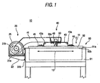
Fig. 1 is a side view of a vacuum chamber and a cover activating device of an embodiment of the invention in a state where a cover of the vacuum chamber is closed; -
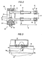
Fig. 2 is a top plan view of the cover activating device shown inFig. 1 ; -
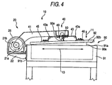
Fig. 3 is a side section view partly showing the vacuum chamber and the cover activating device shown inFig. 1 ; -
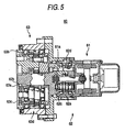
Fig. 4 is a side view of the vacuum chamber shown inFig. 1 , and the cover activating device shown inFig. 1 in a state where the cover of the vacuum chamber is opened by a small angle; -
Fig. 5 is a partially cutaway section view of an actuator of the cover activating device shown inFig. 1 ; and -
Fig. 6 is a view showing relationships between a speed rate of a second reducer of the actuator shown inFig. 5 , an angle formed by a case of the vacuum chamber shown in -
Fig. 1 and a cover, and a ratio of a torque of a motor of the actuator shown inFig. 5 required for closing the cover to a rated torque of the motor. - Hereinafter, an embodiment of the invention will be described with reference to the accompanying drawings.
- First, the configuration of a cover activating device will be described.
- As shown in
Figs. 1 and2 , thecover activating device 10 comprises: ashaft unit 20 which is supported by a vacuum chamber (container) 90 for producing a semiconductor device and having acase 91 and acover 92, and which has arotary shaft 21; anarm unit 40 which is coupled to thecover 92 and therotary shaft 21; and anactuator 60 which drives therotary shaft 21. - In the
case 91 of thevacuum chamber 90, an O-ring which is not shown, and which serves as a sealing member to be in contact with thecover 92 is disposed on anopening face 91a. The O-ring of thecase 91 has a thickness of 1 mm when the O-ring is not in contact with thecover 92. Thecover 92 has aplate 92a on the side opposite to thecase 91. - The
shaft unit 20 comprises: abase 22 which is fixed to one of four side faces of thecase 91 or aside face 91b; a bearing unit 23 which rotatably supports therotary shaft 21; a bearing bracket 24 through which the bearing unit 23 is fixed to thebase 22; and anactuator bracket 25 through which theactuator 60 is fixed to thebase 22. - The
arm unit 40 comprises:arms rotary shaft 21;plate springs arms spring seat plates plate spring 43, and also to thecover 92;spring seat plates plate spring 44, and also to thecover 92; ablock 49 which is fixed to thearm 41; and asensor 50 which is fixed to theblock 49 to measure agap 50a (seeFig. 3 ) between theblock 49 and theplate 92a. - The
plate spring 43 is made of, for example, a metal material, and, when thecover 92 is closed, has abending angle 43a of 105°. The spring constants in the thickness direction of thecover 92 indicated by thearrow 11, in the direction along which therotary shaft 21 elongates, and which is indicated by thearrow 12, and in the direction which is substantially perpendicular to the directions of thearrows arrow 13 are 74 N/mm, 336 N/mm, and 900 N/mm, respectively. Theplate spring 44 is configured in the same manner as thelead spring 43. - The
shaft unit 20 further comprises astopper 26 which is to be in contact with thearm 41, thereby preventing anangle 90a (seeFig. 4 ) formed by theopening face 91a of thecase 91 and aface 92b of thecover 92 which is in contact with the O-ring of thecase 91, from becoming larger than 105°. - As shown in
Fig. 5 , theactuator 60 comprises: amotor 61 having anoutput portion 61a serving as a first output portion from which power is output; afirst reducer 62 having aninput portion 62a serving as a first input portion which receives the power from theoutput portion 61a of themotor 61, and anoutput portion 62b serving as a second output portion from which power is output, the first reducer reducing the output of themotor 61 at a reduction ratio of 1/57; and asecond reducer 63 having aninput portion 63a serving as a second input portion which receives the power from theoutput portion 62b of thefirst reducer 62, and anoutput portion 63b serving as a third output portion from which power is output to the rotary shaft 21 (seeFig. 2 ), the second reducer reducing the output of thefirst reducer 62 at a reduction ratio of 1/141. Namely, thefirst reducer 62 and thesecond reducer 63 transmit the output of themotor 61 to therotary shaft 21 with reducing the output at a reduction ratio of 1/8,037. - The
first reducer 62 is a two-stage reducer having: aspur gear 62c which is a first stage reduction mechanism, and which constitutes theinput portion 62a; and a differentialgear reduction mechanism 62d which is a second stage reduction mechanism. Thespur gear 62c which meshes with a gear disposed in theoutput portion 61a of themotor 61 reduces the speed of transmits the output of themotor 61 at a reduction ratio which is equal to or larger than 1/5 and smaller than 1/1, or transmits the output at a ratio of 1/1. - Similarly, the
second reducer 63 is a two-stage reducer having: aspur gear 63c which is a first stage reduction mechanism, and which constitutes theinput portion 63a; and a differentialgear reduction mechanism 63d which is a second stage reduction mechanism. Thespur gear 63c which meshes with a gear disposed in theoutput portion 62b of thefirst reducer 62 reduces the speed of the output of thefirst reducer 62 at a reduction ratio which is equal to or larger than 1/5 and smaller than 1/1, or transmits the output at a ratio of 1/1. - The reciprocal (hereinafter, referred to as "speed rate") of the reduction ratio of the
second reducer 63 is indicated by R2. The maximum torque which, when thecover 92 is opened, is applied to theoutput portion 63b of thesecond reducer 63 is indicated by TL. A torque which, when a torque is not applied to theinput portion 62a of thefirst reducer 62, is required for rotating theoutput portion 62b of thefirst reducer 62 is indicated by TR1. A torque which, when a torque is not applied to theinput portion 63a of thesecond reducer 63, is required for rotating theoutput portion 63b of thesecond reducer 63 is indicated by TR2. A ratio of a torque which is a remainder of a torque applied to theoutput portion 63b of thesecond reducer 63 after subjecting to a mechanical loss due to thesecond reducer 63, to the torque applied to theoutput portion 63b of thesecond reducer 63 is indicated by η2. In this case, the speed rate R2 is set so as to be larger than a quotient which is obtained by dividing a product of the difference between the maximum value TL and the torque TR2, and the ratio η2, by the torque TR1, or so as to satisfy Expression 1 below.
- Specifically, in the
cover activating device 10 shown inFig. 1 , a torque of 4,606 N·m which is applied to theoutput portion 63b of thesecond reducer 63 when thecover 92 is separated from the O-ring of thecase 91 by a small distance as shown inFig. 4 is the maximum value TL, the torque TR1 is 33 N·m, the torque TR2 is 154 N·m, the ratio η2 is 0.8, and the speed rate R2 is 141. Therefore, the speed rate R2 satisfies Expression 1 as indicated by Expression 2 below.
- The
cover activating device 10 further comprises a control unit which controls the output of themotor 61, and which is not shown. - The position of the
block 49 with respect to thearm 41 is previously adjusted so that, when thecover 92 is closed by the control unit as shown inFig. 1 , thegap 50a (seeFig. 3 ) with respect to theplate 92a is 1 mm, and, when thecover 92 is separated from the O-ring of thecase 91 by a small distance as shown inFig. 4 , thegap 50a is 3 mm. - Next, the operation of the
cover activating device 10 will be described. - When the
cover 92 is closed as shown inFig. 1 , thearms cover 92 toward thecase 91 via the plate springs 43, 44 and thespring seat plates 45 to 48, and hence the O-ring of thecase 91 is compressed by thecover 92. Thegap 50a (seeFig. 3 ) between theblock 49 and theplate 92a is 1 mm, and thebending angle 43a of theplate spring 43 and the bending angle of theplate spring 44 are 105°. - When the
cover activating device 10 is to open thecover 92, the control unit drives themotor 61 so that therotary shaft 21 is rotated by theactuator 60 in the direction indicated by thearrow 21a. Specifically, the control unit controls theactuator 60 so as to rotate therotary shaft 21 at a constant acceleration in the direction of thearrow 21a so that the rotational speed of therotary shaft 21 is changed from 0 deg/sec to 0.13 deg/sec in 0.13 sec, then rotate therotary shaft 21 at 0.13 deg/sec for 12.18 sec in the direction of thearrow 21a, and further rotate therotary shaft 21 at a constant deceleration in the direction of thearrow 21a so that the rotational speed of therotary shaft 21 is changed from 0.13 deg/sec to 0 deg/sec in 0.13 sec. - Therefore, the
cover 92 which is coupled to therotary shaft 21 via thespring seat plates 45 to 48, the plate springs 43, 44, and thearms case 91, to be separated from the O-ring of thecase 91. - When the
cover 92 is opened, thearms cover 92, and hence thebending angle 43a of theplate spring 43 and the bending angle of theplate spring 44 are larger than 105°, and thegap 50a (seeFig. 3 ) between theblock 49 and theplate 92a is larger than 1 mm. - In order to reduce swinging of the
cover 92 which is released from the state of adhering with the O-ring of thecase 91, the control unit controls theactuator 60 so as to stop for 2 sec, and then drives themotor 61 so that therotary shaft 21 is again rotated by theactuator 60 in the direction of thearrow 21a. Specifically, the control unit controls theactuator 60 so as to rotate therotary shaft 21 at a constant acceleration in the direction of thearrow 21a so that the rotational speed of therotary shaft 21 is changed from 0 deg/sec to 1.059 deg/sec in 1.06 sec, then rotate therotary shaft 21 at 1.059 deg/sec for 87.705 sec in the direction of thearrow 21a, and further rotate therotary shaft 21 at a constant deceleration in the direction of thearrow 21a so that the rotational speed of therotary shaft 21 is changed from 1.059 deg/sec to 0 deg/sec in 1.06 sec. - When the
cover 92 is opened by thecover activating device 10, therotary shaft 21 is rotated in total by about 95.6° in the direction of thearrow 21a as a result of the series of above-described operations. However, the plate springs 43, 44 are deformed, and hence theangle 90a (seeFig. 4 ) formed by theopening face 91a of thecase 91 and theface 92b of thecover 92 is not 95.6° but 95°. - When the
cover 92 is closed by thecover activating device 10 in the case where theangle 90a (seeFig. 4 ) formed by theopening face 91a of thecase 91, and theface 92b of thecover 92 is 95°, the control unit drives themotor 61 so that therotary shaft 21 is rotated by theactuator 60 in the direction indicated by thearrow 21b. Specifically, the control unit controls theactuator 60 so as to rotate therotary shaft 21 at a constant acceleration in the direction of thearrow 21b so that the rotational speed of therotary shaft 21 is changed from 0 deg/sec to 1.059 deg/sec in 1.06 sec, then rotate therotary shaft 21 at 1.059 deg/sec for 87.705 sec in the direction of thearrow 21b, and further rotate therotary shaft 21 at a constant deceleration in the direction of thearrow 21a so that the rotational speed of therotary shaft 21 is changed from 1.059 deg/sec to 0 deg/sec in 1.06 sec. - In order to reduce swinging of the
cover 92, the control unit controls theactuator 60 so as to stop for 2 sec, and then drives themotor 61 so that therotary shaft 21 is again rotated by theactuator 60 in the direction of thearrow 21b. Specifically, the control unit controls theactuator 60 so as to rotate therotary shaft 21 at a constant acceleration in the direction of thearrow 21b so that the rotational speed of therotary shaft 21 is changed from 0 deg/sec to 0.13 deg/sec in 0.13 sec, then rotate therotary shaft 21 at 0.13 deg/sec for 12.18 sec in the direction of thearrow 21b, and further rotate therotary shaft 21 at a constant deceleration in the direction of thearrow 21b so that the rotational speed of therotary shaft 21 is changed from 0.13 deg/sec to 0 deg/sec in 0.13 sec. - Therefore, the
cover 92 which is coupled to therotary shaft 21 via thespring seat plates 45 to 48, the plate springs 43, 44, and thearms case 91 in the state where the cover compresses the O-ring of thecase 91. - When the
cover 92 is closed, thearms cover 92, and hence thebending angle 43a of theplate spring 43 and the bending angle of theplate spring 44 are 105°, and thegap 50a (seeFig. 3 ) between theblock 49 and theplate 92a is 1 mm. - when the
cover 92 is closed by thecover activating device 10, therotary shaft 21 is rotated in total by about 95.6° in the direction of thearrow 21b as a result of the series of above-described operations. However, the plate springs 43, 44 are deformed, and hence theangle 90a (seeFig. 4 ) formed by theopening face 91a of thecase 91 and theface 92b of thecover 92 which is in contact with the O-ring of thecase 91 is not -0.6° but 0°. - Irrespective of whether the
cover 92 is being opened by thecover activating device 10 or thecover 92 is being closed by thecover activating device 10, when a torque is applied to theoutput portion 63b of thesecond reducer 63 by the weight of thecover 92 in the state where thecover 92 is opened, a torque which is transmitted by the weight of thecover 92 to theoutput portion 62b of thefirst reducer 62 via theinput portion 63a of thesecond reducer 63 is equal to or smaller than the value indicated by Expression 3 below.
- When the torque TR1 is larger than the value indicated by Expression 3 above, or satisfies Expression 4 below, the
output portion 62b of thefirst reducer 62 is not rotated by the weight of thecover 92.
- In the
cover activating device 10, since the speed rate R2 is set so as to satisfy Expression 1, the torque TR1 satisfies Expression 4, and, when thecover 92 is opened, closing of thecover 92 due to its own weight is suppressed by theactuator 60. - For example, the speed rate R2, the
angle 90a (seeFig. 4 ) formed by theopening face 91a of thecase 91 and theface 92b of thecover 92, and a ratio of the torque of themotor 61 required for closing thecover 92 to the rated torque of themotor 61 have relationships shown inFig. 6 . When the speed rate R2 is 81 which is smaller than 107.9 indicated by Expression 2, and theangle 90a is larger than about 45°, the torque of themotor 61 is required for closing thecover 92, and hence thecover activating device 10 can suppress closing of thecover 92 due to its own weight. When the speed rate R2 is 81 and theangle 90a is equal to or smaller than about 45°, the torque of themotor 61 is not required for closing thecover 92, and hence thecover activating device 10 cannot suppress closing of thecover 92 due to its own weight. By contrast, in the case where the speed rate R2 is 141 which is larger than 107.9 indicated by Expression 2, when theangle 90a is equal to or larger than 0° and equal to or smaller than 90°, the torque of themotor 61 is always required for closing thecover 92, and hence thecover activating device 10 can suppress closing of thecover 92 due to its own weight. - As described above, in the
cover activating device 10, closing of thecover 92 due to its own weight can be suppressed, by theactuator 60 which drives thecover 92. Therefore, the apparatus can be made smaller in size than a conventional apparatus. - In the
cover activating device 10, closing of thecover 92 due to own weight is suppressed by the differentialgear reduction mechanism 62d which transmits power from themotor 61 to thecover 92 at a higher efficiency than that of a worm gear. Therefore, the efficiency of transmission of power from themotor 61 to thecover 92 can be improved as compared with the case where closing of a cover due to its own weight can be suppressed by a worm gear. - In the
cover activating device 10, the reduction ratio of thefirst reducer 62 or thesecond reducer 63 can be controlled simply by adjusting the reduction ratio of thespur gear 62c or thespur gear 63c which is the first stage reduction mechanism. Therefore, the reduction ratio of thefirst reducer 62 or thesecond reducer 63 can be easily controlled as compared with the case where the reduction ratio of thefirst reducer 62 or thesecond reducer 63 can be controlled only after the reduction ratio of the differentialgear reduction mechanism 62d or the differentialgear reduction mechanism 63d is adjusted. - In the
cover activating device 10, as described above, the plate springs 43, 44 enable thecover 92 to be moved in the thickness direction of thecover 92 indicated by thearrow 11. When thecover 92 is closed, therefore, thecover 92 can make contact with the O-ring of thecase 91 without causing a shock, and closely adhere at a uniform pressure with the O-ring of thecase 91. During the process of combining thecover activating device 10, thecase 91, and thecover 92 with each other, therefore, steps of positioning and adjusting them with using actual components can be omitted, and the durability of the O-ring of thecase 91 can be maintained. - In the
cover activating device 10, the spring constants of the plate springs 43, 44 in the directions of thearrows arrows arrow 11. Therefore, swinging of thecover 92 in the directions of thearrows cover 92 to be moved in the direction of thearrow 11. - In the
cover activating device 10, when thecover 92 is closed, the bendingangle 43a of theplate spring 43 and the bending angle of theplate spring 44 are 105° or not an acute angle, and, during the process of opening or closing thecover 92, the bendingangle 43a of theplate spring 43 and the bending angle of theplate spring 44 are not formed as an acute angle. Therefore, repeated fatigue of the plate springs 43, 44 due to opening and closing of thecover 92 is hardly caused as compared with the case where, during the process of opening or closing thecover 92, the bendingangle 43a of theplate spring 43 and the bending angle of theplate spring 44 are formed as an acute angle. In thecover activating device 10, when thecover 92 is closed, the bendingangle 43a of theplate spring 43 and the bending angle of theplate spring 44 are not formed as an acute angle, and, when no load is applied to the plate springs 43, 44, the bendingangle 43a of theplate spring 43 and the bending angle of theplate spring 44 are not formed as an acute angle. Therefore, the plate springs 43, 44 can be easily shaped as compared with the case where, when no load is applied to the plate springs 43, 44, the bendingangle 43a of theplate spring 43 and the bending angle of theplate spring 44 are formed as an acute angle. - In the
cover activating device 10, the plate springs 43, 44 are fixed to thecover 92 via thespring seat plates 45 to 48. Alternatively, the plate springs 43, 44 may be fixed directly to thecover 92. - In the
cover activating device 10, each of the plate springs 43, 44 is formed by a single elastic member. Alternatively, each of the plate springs 43, 44 may be formed by plural elastic members. - In the
cover activating device 10, thegap 50a (seeFig. 3 ) between theplate 92a fixed to thecover 92 and theblock 49 is measured by thesensor 50. In the case where theplate 92a is not fixed to thecover 92, the gap between thecover 92 and theblock 49 may be measured by thesensor 50. - The
cover activating device 10 is fixed to theside face 91b which is one of the four side faces of thecase 91. Therefore, a loading and unloading port for a product such as a liquid crystal display device may be formed in one of the four side faces of thecase 91 other than theside face 91b. - The
cover activating device 10 is configured so as to open and close thecover 92 of thevacuum chamber 90 for producing a semiconductor device. Alternatively, the apparatus may be configured so as to open and close a cover of a container other than thevacuum chamber 90. - As described above, the activating device for a cover according to the invention attains an effect that it can be made smaller in size than a conventional apparatus, and is useful as, for example, an activating device for a cover of a vacuum chamber for producing a semiconductor device.
Claims (1)
- A cover with an activating device and the activating device that is adapted for interacting with the cover, comprising:a shaft unit, which is supported by a case of a container, having a rotary shaft;an arm unit coupled to said cover and said rotary shaft; andan actuator which drives said rotary shaft, said actuator including:and aa motor (61) having a first output portion (62a) from which a power is output;a first reducer (62) having a first input portion (62a) receiving the power from said first output portion, and a second output portion (62b) from which a power is output, said first reducer reducing & speed of the output of said motor; anda second reducer(63) having a second input portion (63a) which receives the power from said second output portion, and a third output portion (63b) from which a power is output to said rotary shaft, said second reducer (63) reducing a speed of the output of said first reducer (62), wherein each of said first reducer (62) and said second reducer (63) includes: a first stage reduction mechanism which is a reduction mechanism other than a differential gear reduction mechanism; and a second stage reduction mechanism which is differential gear reduction mechanism.
following equation is satisfied:
whereinR2 is a reciprocal of a reduction ratio of said second reducer (63),TR1 is a torque required for rotating said second output portion (62b) when a torque is not applied to said first input portion (62a),TL is a maximum torque applied to said third output portion (63b),TR2 is a torque required for rotating said third output portion (63b) when a torque ia not applied to said second input portion,η2 is a ratio of a remainder torque after subjecting to a mechanical loss due to said second reducer (63), to the torque applied to said third output portion (63b).
Applications Claiming Priority (2)
| Application Number | Priority Date | Filing Date | Title |
|---|---|---|---|
| JP2003277497 | 2003-07-22 | ||
| JP2003277497A JP2005042816A (en) | 2003-07-22 | 2003-07-22 | Cover opening/closing apparatus |
Publications (3)
| Publication Number | Publication Date |
|---|---|
| EP1500851A2 EP1500851A2 (en) | 2005-01-26 |
| EP1500851A3 EP1500851A3 (en) | 2010-08-04 |
| EP1500851B1 true EP1500851B1 (en) | 2012-09-05 |
Family
ID=33487678
Family Applications (1)
| Application Number | Title | Priority Date | Filing Date |
|---|---|---|---|
| EP04017389A Not-in-force EP1500851B1 (en) | 2003-07-22 | 2004-07-22 | Apparatus for opening and closing cover |
Country Status (6)
| Country | Link |
|---|---|
| US (2) | US7213481B2 (en) |
| EP (1) | EP1500851B1 (en) |
| JP (1) | JP2005042816A (en) |
| KR (1) | KR20050012166A (en) |
| CN (2) | CN100570180C (en) |
| TW (1) | TWI315375B (en) |
Families Citing this family (13)
| Publication number | Priority date | Publication date | Assignee | Title |
|---|---|---|---|---|
| KR100740451B1 (en) | 2005-10-17 | 2007-07-18 | 주식회사 에이디피엔지니어링 | Apparatus for vacuum processing |
| JP4556890B2 (en) * | 2005-05-16 | 2010-10-06 | パナソニック株式会社 | Image forming apparatus |
| JP5060969B2 (en) * | 2008-01-15 | 2012-10-31 | 住友重機械工業株式会社 | Robot joint drive device |
| JP5359320B2 (en) * | 2009-01-29 | 2013-12-04 | 株式会社ジェイテクト | Machine Tools |
| JP5533194B2 (en) * | 2010-04-23 | 2014-06-25 | 株式会社ジェイテクト | Transmission gear unit |
| KR101124022B1 (en) * | 2011-05-13 | 2012-03-23 | (주)엠제이티 | Automatic door opening-closing apparatus and etching solution container |
| KR101592484B1 (en) * | 2012-03-16 | 2016-02-18 | 스미도모쥬기가이고교 가부시키가이샤 | Drive method and turning device for heavy turning body |
| CN202863979U (en) * | 2012-05-29 | 2013-04-10 | 丁仁世 | Infrared induction type container with cover opened and closed automatically |
| US9394731B2 (en) * | 2013-10-03 | 2016-07-19 | Vac-Tron Equipment, Llc | Door lock system for debris tank |
| CN104616642B (en) * | 2015-01-06 | 2017-09-15 | 云南格律乐器制造有限公司 | A kind of self-leveling accordion sound hole cover of energy |
| DE102015014087B4 (en) * | 2015-11-03 | 2017-11-09 | Sew-Eurodrive Gmbh & Co Kg | transmission |
| US11268301B2 (en) * | 2017-04-27 | 2022-03-08 | Reinhard Matye | Automatic hatch for bulk material containers |
| FR3130007A1 (en) * | 2021-12-03 | 2023-06-09 | Getinge Life Science France | Motorized watertight cell door for double door connection system |
Citations (1)
| Publication number | Priority date | Publication date | Assignee | Title |
|---|---|---|---|---|
| JPS63243547A (en) * | 1987-03-27 | 1988-10-11 | Sumitomo Heavy Ind Ltd | Speed increasing/decreasing gear having planetary gear mechanism |
Family Cites Families (16)
| Publication number | Priority date | Publication date | Assignee | Title |
|---|---|---|---|---|
| US2884159A (en) * | 1956-01-20 | 1959-04-28 | Owens Corning Fiberglass Corp | Closure operating device |
| AT380222B (en) * | 1984-06-01 | 1986-04-25 | Philips Nv | CORKSCREW |
| CA1244855A (en) * | 1985-01-18 | 1988-11-15 | Kazuyuki Matsumoto | Robot arm drive apparatus of industrial robot |
| US4625888A (en) * | 1985-11-18 | 1986-12-02 | Thompson Andy L | Ground actuated lid operating system |
| EP0305535B1 (en) * | 1987-02-27 | 1993-09-08 | Sumitomo Heavy Industries, Ltd | Epicyclic reduction gear |
| JPS63243597A (en) | 1987-03-30 | 1988-10-11 | Tokyo Electric Power Co Inc:The | Automatic cleaning device movable between orthogonal crossing rails for open rack type carburetor |
| JP3357143B2 (en) * | 1993-09-30 | 2002-12-16 | ファナック株式会社 | Robot controller that monitors the load on the robot |
| SE505993C2 (en) * | 1994-06-29 | 1997-10-27 | Volvo Ab | Power unit for a motor vehicle |
| US6029532A (en) * | 1997-01-31 | 2000-02-29 | Reliance Electric Industrial Company | Gearing commonality system for gear reducers |
| DE60029662T2 (en) * | 1999-03-16 | 2007-08-09 | Sumitomo Heavy Industries, Ltd. | Cycloidal gear and planetary friction gear |
| JP4349688B2 (en) * | 1999-06-23 | 2009-10-21 | 日産自動車株式会社 | Vehicle drive device |
| JP2001021039A (en) | 1999-07-07 | 2001-01-26 | Hitachi Kokusai Electric Inc | Semiconductor manufacturing device |
| IT1317174B1 (en) * | 2000-04-06 | 2003-05-27 | Giacomini Spa | PERFECTED ACTUATOR FOR WATER AND SANITARY HEATING / COOLING SYSTEMS |
| JP4636651B2 (en) * | 2000-04-07 | 2011-02-23 | Gknドライブラインジャパン株式会社 | Power transmission device |
| JP4226190B2 (en) * | 2000-04-25 | 2009-02-18 | 住重機器システム株式会社 | Lid opening / closing drive device |
| US6796921B1 (en) * | 2003-05-30 | 2004-09-28 | One World Technologies Limited | Three speed rotary power tool |
-
2003
- 2003-07-22 JP JP2003277497A patent/JP2005042816A/en active Pending
-
2004
- 2004-07-22 CN CNB200710196463XA patent/CN100570180C/en active Active
- 2004-07-22 CN CNB2004100544596A patent/CN100365320C/en not_active Expired - Fee Related
- 2004-07-22 EP EP04017389A patent/EP1500851B1/en not_active Not-in-force
- 2004-07-22 TW TW093121909A patent/TWI315375B/en not_active IP Right Cessation
- 2004-07-22 US US10/896,661 patent/US7213481B2/en not_active Expired - Fee Related
- 2004-07-22 KR KR1020040057378A patent/KR20050012166A/en active Search and Examination
-
2007
- 2007-04-09 US US11/697,820 patent/US7381145B2/en active Active
Patent Citations (1)
| Publication number | Priority date | Publication date | Assignee | Title |
|---|---|---|---|---|
| JPS63243547A (en) * | 1987-03-27 | 1988-10-11 | Sumitomo Heavy Ind Ltd | Speed increasing/decreasing gear having planetary gear mechanism |
Also Published As
| Publication number | Publication date |
|---|---|
| JP2005042816A (en) | 2005-02-17 |
| CN1576661A (en) | 2005-02-09 |
| EP1500851A2 (en) | 2005-01-26 |
| CN100365320C (en) | 2008-01-30 |
| US7213481B2 (en) | 2007-05-08 |
| CN100570180C (en) | 2009-12-16 |
| EP1500851A3 (en) | 2010-08-04 |
| US7381145B2 (en) | 2008-06-03 |
| TWI315375B (en) | 2009-10-01 |
| KR20050012166A (en) | 2005-01-31 |
| US20050016321A1 (en) | 2005-01-27 |
| CN101173712A (en) | 2008-05-07 |
| US20070179005A1 (en) | 2007-08-02 |
| TW200508526A (en) | 2005-03-01 |
Similar Documents
| Publication | Publication Date | Title |
|---|---|---|
| US7381145B2 (en) | Apparatus for opening and closing cover | |
| US6217094B1 (en) | Object holding device | |
| JP4268881B2 (en) | Lift assist mechanism for vehicle tailgate | |
| US9958368B2 (en) | Rheometer control system | |
| HU195293B (en) | Device for adjusting butterfly valve and method for operating the device | |
| US20180372189A1 (en) | Smart Self-Adaptive Planetary Transmission Device With Small Tooth Number Difference | |
| US8294406B2 (en) | Parallel kinematics micro-positioning system | |
| US7093733B2 (en) | Cover activating device | |
| JP2000237988A (en) | Arm driving mechanism of robot device | |
| JP3750934B2 (en) | Inlet throttle device | |
| CN110779756B (en) | Online sampling device of battery pole piece | |
| CN210913073U (en) | Double-door discharging device | |
| CN215761149U (en) | Vacuum chamber | |
| CN218344537U (en) | Discharge valve for aluminum oxide collecting hopper | |
| JPH04294984A (en) | Jointless vacuum robot | |
| US20230407692A1 (en) | Powered vehicle closure system having non-linear torsion bar | |
| JPH06148362A (en) | Information processing apparatus | |
| CN215514400U (en) | Simple and easy manual regulation opens a bag width mechanism | |
| JPH0639380Y2 (en) | Feed belt drive for coin processing machine | |
| JP2005015209A (en) | Transport roller pressing mechanism with balance adjusting function | |
| CA2603966A1 (en) | Intermediate cash box | |
| JPH0371866A (en) | Bail operating device of paper feed device | |
| JPH08244457A (en) | Door check device for vehicle | |
| JPH04321493A (en) | Rotation drive mechanism | |
| JPH06217900A (en) | Toilet seat and device for automatically opening and closing lid of toilet seat |
Legal Events
| Date | Code | Title | Description |
|---|---|---|---|
| PUAI | Public reference made under article 153(3) epc to a published international application that has entered the european phase |
Free format text: ORIGINAL CODE: 0009012 |
|
| AK | Designated contracting states |
Kind code of ref document: A2 Designated state(s): AT BE BG CH CY CZ DE DK EE ES FI FR GB GR HU IE IT LI LU MC NL PL PT RO SE SI SK TR |
|
| AX | Request for extension of the european patent |
Extension state: AL HR LT LV MK |
|
| PUAL | Search report despatched |
Free format text: ORIGINAL CODE: 0009013 |
|
| AK | Designated contracting states |
Kind code of ref document: A3 Designated state(s): AT BE BG CH CY CZ DE DK EE ES FI FR GB GR HU IE IT LI LU MC NL PL PT RO SE SI SK TR |
|
| AX | Request for extension of the european patent |
Extension state: AL HR LT LV MK |
|
| RIC1 | Information provided on ipc code assigned before grant |
Ipc: F16J 13/00 20060101AFI20040928BHEP Ipc: B65D 90/10 20060101ALI20100630BHEP Ipc: F16H 1/32 20060101ALI20100630BHEP |
|
| 17P | Request for examination filed |
Effective date: 20110204 |
|
| AKX | Designation fees paid |
Designated state(s): AT BE BG CH CY CZ DE DK EE ES FI FR GB GR HU IE IT LI LU MC NL PL PT RO SE SI SK TR |
|
| 17Q | First examination report despatched |
Effective date: 20111104 |
|
| GRAP | Despatch of communication of intention to grant a patent |
Free format text: ORIGINAL CODE: EPIDOSNIGR1 |
|
| GRAS | Grant fee paid |
Free format text: ORIGINAL CODE: EPIDOSNIGR3 |
|
| GRAA | (expected) grant |
Free format text: ORIGINAL CODE: 0009210 |
|
| AK | Designated contracting states |
Kind code of ref document: B1 Designated state(s): AT BE BG CH CY CZ DE DK EE ES FI FR GB GR HU IE IT LI LU MC NL PL PT RO SE SI SK TR |
|
| REG | Reference to a national code |
Ref country code: GB Ref legal event code: FG4D |
|
| REG | Reference to a national code |
Ref country code: CH Ref legal event code: EP |
|
| REG | Reference to a national code |
Ref country code: AT Ref legal event code: REF Ref document number: 574285 Country of ref document: AT Kind code of ref document: T Effective date: 20120915 |
|
| REG | Reference to a national code |
Ref country code: IE Ref legal event code: FG4D |
|
| REG | Reference to a national code |
Ref country code: DE Ref legal event code: R096 Ref document number: 602004039190 Country of ref document: DE Effective date: 20121031 |
|
| REG | Reference to a national code |
Ref country code: AT Ref legal event code: MK05 Ref document number: 574285 Country of ref document: AT Kind code of ref document: T Effective date: 20120905 |
|
| REG | Reference to a national code |
Ref country code: NL Ref legal event code: VDEP Effective date: 20120905 |
|
| PG25 | Lapsed in a contracting state [announced via postgrant information from national office to epo] |
Ref country code: FI Free format text: LAPSE BECAUSE OF FAILURE TO SUBMIT A TRANSLATION OF THE DESCRIPTION OR TO PAY THE FEE WITHIN THE PRESCRIBED TIME-LIMIT Effective date: 20120905 Ref country code: AT Free format text: LAPSE BECAUSE OF FAILURE TO SUBMIT A TRANSLATION OF THE DESCRIPTION OR TO PAY THE FEE WITHIN THE PRESCRIBED TIME-LIMIT Effective date: 20120905 Ref country code: CY Free format text: LAPSE BECAUSE OF FAILURE TO SUBMIT A TRANSLATION OF THE DESCRIPTION OR TO PAY THE FEE WITHIN THE PRESCRIBED TIME-LIMIT Effective date: 20120905 |
|
| PG25 | Lapsed in a contracting state [announced via postgrant information from national office to epo] |
Ref country code: SE Free format text: LAPSE BECAUSE OF FAILURE TO SUBMIT A TRANSLATION OF THE DESCRIPTION OR TO PAY THE FEE WITHIN THE PRESCRIBED TIME-LIMIT Effective date: 20120905 Ref country code: SI Free format text: LAPSE BECAUSE OF FAILURE TO SUBMIT A TRANSLATION OF THE DESCRIPTION OR TO PAY THE FEE WITHIN THE PRESCRIBED TIME-LIMIT Effective date: 20120905 Ref country code: GR Free format text: LAPSE BECAUSE OF FAILURE TO SUBMIT A TRANSLATION OF THE DESCRIPTION OR TO PAY THE FEE WITHIN THE PRESCRIBED TIME-LIMIT Effective date: 20121206 |
|
| PG25 | Lapsed in a contracting state [announced via postgrant information from national office to epo] |
Ref country code: ES Free format text: LAPSE BECAUSE OF FAILURE TO SUBMIT A TRANSLATION OF THE DESCRIPTION OR TO PAY THE FEE WITHIN THE PRESCRIBED TIME-LIMIT Effective date: 20121216 Ref country code: CZ Free format text: LAPSE BECAUSE OF FAILURE TO SUBMIT A TRANSLATION OF THE DESCRIPTION OR TO PAY THE FEE WITHIN THE PRESCRIBED TIME-LIMIT Effective date: 20120905 Ref country code: BE Free format text: LAPSE BECAUSE OF FAILURE TO SUBMIT A TRANSLATION OF THE DESCRIPTION OR TO PAY THE FEE WITHIN THE PRESCRIBED TIME-LIMIT Effective date: 20120905 Ref country code: EE Free format text: LAPSE BECAUSE OF FAILURE TO SUBMIT A TRANSLATION OF THE DESCRIPTION OR TO PAY THE FEE WITHIN THE PRESCRIBED TIME-LIMIT Effective date: 20120905 Ref country code: NL Free format text: LAPSE BECAUSE OF FAILURE TO SUBMIT A TRANSLATION OF THE DESCRIPTION OR TO PAY THE FEE WITHIN THE PRESCRIBED TIME-LIMIT Effective date: 20120905 Ref country code: RO Free format text: LAPSE BECAUSE OF FAILURE TO SUBMIT A TRANSLATION OF THE DESCRIPTION OR TO PAY THE FEE WITHIN THE PRESCRIBED TIME-LIMIT Effective date: 20120905 |
|
| PG25 | Lapsed in a contracting state [announced via postgrant information from national office to epo] |
Ref country code: SK Free format text: LAPSE BECAUSE OF FAILURE TO SUBMIT A TRANSLATION OF THE DESCRIPTION OR TO PAY THE FEE WITHIN THE PRESCRIBED TIME-LIMIT Effective date: 20120905 Ref country code: PL Free format text: LAPSE BECAUSE OF FAILURE TO SUBMIT A TRANSLATION OF THE DESCRIPTION OR TO PAY THE FEE WITHIN THE PRESCRIBED TIME-LIMIT Effective date: 20120905 Ref country code: PT Free format text: LAPSE BECAUSE OF FAILURE TO SUBMIT A TRANSLATION OF THE DESCRIPTION OR TO PAY THE FEE WITHIN THE PRESCRIBED TIME-LIMIT Effective date: 20130107 |
|
| PLBE | No opposition filed within time limit |
Free format text: ORIGINAL CODE: 0009261 |
|
| STAA | Information on the status of an ep patent application or granted ep patent |
Free format text: STATUS: NO OPPOSITION FILED WITHIN TIME LIMIT |
|
| PG25 | Lapsed in a contracting state [announced via postgrant information from national office to epo] |
Ref country code: BG Free format text: LAPSE BECAUSE OF FAILURE TO SUBMIT A TRANSLATION OF THE DESCRIPTION OR TO PAY THE FEE WITHIN THE PRESCRIBED TIME-LIMIT Effective date: 20121205 Ref country code: DK Free format text: LAPSE BECAUSE OF FAILURE TO SUBMIT A TRANSLATION OF THE DESCRIPTION OR TO PAY THE FEE WITHIN THE PRESCRIBED TIME-LIMIT Effective date: 20120905 |
|
| 26N | No opposition filed |
Effective date: 20130606 |
|
| PG25 | Lapsed in a contracting state [announced via postgrant information from national office to epo] |
Ref country code: IT Free format text: LAPSE BECAUSE OF FAILURE TO SUBMIT A TRANSLATION OF THE DESCRIPTION OR TO PAY THE FEE WITHIN THE PRESCRIBED TIME-LIMIT Effective date: 20120905 |
|
| REG | Reference to a national code |
Ref country code: DE Ref legal event code: R097 Ref document number: 602004039190 Country of ref document: DE Effective date: 20130606 |
|
| PG25 | Lapsed in a contracting state [announced via postgrant information from national office to epo] |
Ref country code: MC Free format text: LAPSE BECAUSE OF FAILURE TO SUBMIT A TRANSLATION OF THE DESCRIPTION OR TO PAY THE FEE WITHIN THE PRESCRIBED TIME-LIMIT Effective date: 20120905 |
|
| REG | Reference to a national code |
Ref country code: CH Ref legal event code: PL |
|
| GBPC | Gb: european patent ceased through non-payment of renewal fee |
Effective date: 20130722 |
|
| REG | Reference to a national code |
Ref country code: IE Ref legal event code: MM4A |
|
| REG | Reference to a national code |
Ref country code: FR Ref legal event code: ST Effective date: 20140331 |
|
| PG25 | Lapsed in a contracting state [announced via postgrant information from national office to epo] |
Ref country code: GB Free format text: LAPSE BECAUSE OF NON-PAYMENT OF DUE FEES Effective date: 20130722 Ref country code: LI Free format text: LAPSE BECAUSE OF NON-PAYMENT OF DUE FEES Effective date: 20130731 Ref country code: CH Free format text: LAPSE BECAUSE OF NON-PAYMENT OF DUE FEES Effective date: 20130731 |
|
| PG25 | Lapsed in a contracting state [announced via postgrant information from national office to epo] |
Ref country code: FR Free format text: LAPSE BECAUSE OF NON-PAYMENT OF DUE FEES Effective date: 20130731 |
|
| PG25 | Lapsed in a contracting state [announced via postgrant information from national office to epo] |
Ref country code: IE Free format text: LAPSE BECAUSE OF NON-PAYMENT OF DUE FEES Effective date: 20130722 |
|
| PG25 | Lapsed in a contracting state [announced via postgrant information from national office to epo] |
Ref country code: TR Free format text: LAPSE BECAUSE OF FAILURE TO SUBMIT A TRANSLATION OF THE DESCRIPTION OR TO PAY THE FEE WITHIN THE PRESCRIBED TIME-LIMIT Effective date: 20120905 |
|
| PG25 | Lapsed in a contracting state [announced via postgrant information from national office to epo] |
Ref country code: HU Free format text: LAPSE BECAUSE OF FAILURE TO SUBMIT A TRANSLATION OF THE DESCRIPTION OR TO PAY THE FEE WITHIN THE PRESCRIBED TIME-LIMIT; INVALID AB INITIO Effective date: 20040722 Ref country code: LU Free format text: LAPSE BECAUSE OF NON-PAYMENT OF DUE FEES Effective date: 20130722 |
|
| PGFP | Annual fee paid to national office [announced via postgrant information from national office to epo] |
Ref country code: DE Payment date: 20150721 Year of fee payment: 12 |
|
| REG | Reference to a national code |
Ref country code: DE Ref legal event code: R119 Ref document number: 602004039190 Country of ref document: DE |
|
| PG25 | Lapsed in a contracting state [announced via postgrant information from national office to epo] |
Ref country code: DE Free format text: LAPSE BECAUSE OF NON-PAYMENT OF DUE FEES Effective date: 20170201 |