EP1500846B2 - Hydraulic mount - Google Patents
Hydraulic mount Download PDFInfo
- Publication number
- EP1500846B2 EP1500846B2 EP03720976.4A EP03720976A EP1500846B2 EP 1500846 B2 EP1500846 B2 EP 1500846B2 EP 03720976 A EP03720976 A EP 03720976A EP 1500846 B2 EP1500846 B2 EP 1500846B2
- Authority
- EP
- European Patent Office
- Prior art keywords
- fluid
- cap
- stud
- damping
- filled mount
- Prior art date
- Legal status (The legal status is an assumption and is not a legal conclusion. Google has not performed a legal analysis and makes no representation as to the accuracy of the status listed.)
- Expired - Lifetime
Links
Images


Classifications
-
- F—MECHANICAL ENGINEERING; LIGHTING; HEATING; WEAPONS; BLASTING
- F16—ENGINEERING ELEMENTS AND UNITS; GENERAL MEASURES FOR PRODUCING AND MAINTAINING EFFECTIVE FUNCTIONING OF MACHINES OR INSTALLATIONS; THERMAL INSULATION IN GENERAL
- F16F—SPRINGS; SHOCK-ABSORBERS; MEANS FOR DAMPING VIBRATION
- F16F13/00—Units comprising springs of the non-fluid type as well as vibration-dampers, shock-absorbers, or fluid springs
- F16F13/005—Units comprising springs of the non-fluid type as well as vibration-dampers, shock-absorbers, or fluid springs comprising both a wound spring and a damper, e.g. a friction damper
- F16F13/007—Units comprising springs of the non-fluid type as well as vibration-dampers, shock-absorbers, or fluid springs comprising both a wound spring and a damper, e.g. a friction damper the damper being a fluid damper
-
- F—MECHANICAL ENGINEERING; LIGHTING; HEATING; WEAPONS; BLASTING
- F16—ENGINEERING ELEMENTS AND UNITS; GENERAL MEASURES FOR PRODUCING AND MAINTAINING EFFECTIVE FUNCTIONING OF MACHINES OR INSTALLATIONS; THERMAL INSULATION IN GENERAL
- F16F—SPRINGS; SHOCK-ABSORBERS; MEANS FOR DAMPING VIBRATION
- F16F13/00—Units comprising springs of the non-fluid type as well as vibration-dampers, shock-absorbers, or fluid springs
- F16F13/04—Units comprising springs of the non-fluid type as well as vibration-dampers, shock-absorbers, or fluid springs comprising both a plastics spring and a damper, e.g. a friction damper
- F16F13/06—Units comprising springs of the non-fluid type as well as vibration-dampers, shock-absorbers, or fluid springs comprising both a plastics spring and a damper, e.g. a friction damper the damper being a fluid damper, e.g. the plastics spring not forming a part of the wall of the fluid chamber of the damper
- F16F13/08—Units comprising springs of the non-fluid type as well as vibration-dampers, shock-absorbers, or fluid springs comprising both a plastics spring and a damper, e.g. a friction damper the damper being a fluid damper, e.g. the plastics spring not forming a part of the wall of the fluid chamber of the damper the plastics spring forming at least a part of the wall of the fluid chamber of the damper
Definitions
- the present invention relates to a liquid seal type fluid-filled mount as defined in the preamble of claim 1 and comprising a movable damping plate and a fixed damping unit, which is advantageous in terms of enlarged vertical strokes and high damping effect.
- the liquid seal type fluid-filled mount disclosed in Japanese Patent Laid-open Publication No. H7-127683 is as follows.
- a damping plate is disposed at a lower end of a stud that supports a target vibrating material.
- the damping plate is housed in a cup-shaped housing with a closed bottom portion, and in the same time, a viscous fluid is filled in the cup-shaped housing (i.e. a liquid seal type fluid-filled mount).
- the liquid seal type fluid-filled mount further comprises a spring for absorbing impact disposed between the damping plate and the bottom portion of the cup-shaped housing.
- an elastic cylindrical body is fixed at a top portion of the cup-shaped housing and the stud is fitted into the elastic cylindrical body to be axially slidable, via a sleeve being placed between the stud and the elastic cylindrical body.
- a liquid seal type fluid-filled mount of a type mentioned as above can have a large vertical stroke and high damping effect.
- the elastic cylindrical body should be mounted at the top portion of the cup-shaped housing and the sleeve should be disposed inside the elastic cylindrical body. Further, in order to enclose a space between an inner surface of the sleeve and an outer surface of the stud, bellows should be integrally connected between a lower end of the elastic cylindrical body and the movable damping plate.
- the stud should be installed to be axially slidable in the sleeve.
- the conventional liquid seal type fluid-filled mount has a complicated structure, with a service life of the bellows being short, and also risking possible leakage of high viscosity fluid.
- the object of the present invention is to provide a liquid seal type fluid-filled mount comprising a movable damping plate and a fixed damping unit.
- Another object of the present invention is to provide a liquid seal type fluid-filled mount that enables high damping effect.
- Yet another object of the present invention is to provide a liquid seal type fluid-filled mount that enables large strokes.
- Still another object of the present invention is to provide a liquid seal type fluid-filled mount with a simple structure in sealing a high viscosity fluid.
- a still further object of the present invention is to provide a liquid seal type fluid-filled mount with improved strength against lateral impact using a simple structure.
- a still further object of the present invention is to provide a liquid seal type fluid-filled mount capable of damping external high frequency vibrations using a simple structure.
- a still further object of the present invention is to provide a liquid seal type fluid-filled mount capable of obtaining high damping effect even though a stud is tilted by inclined lateral impact from outside.
- the second holder has a flange portion and a cylindrical portion, and the cylindrical portion is vulcanized to an outer circumferential side of the cap body.
- the flexible seal cap has a layered cap
- the second holder has a flange portion and a cylindrical portion
- the cylindrical portion is vulcanized to an outer circumferential side of the layered cap and the layered cap has N number of elastic materials such as rubber rings being formed into cylindrical shape, and N-1 number of bushes, and the elastic materials and the bushes are being alternately layered.
- the elastic material is rubber having a predetermined thickness.
- the central opening formed at a center of the fixed damping unit has at least one groove at an inner surface thereof.
- the central opening formed at the center of the fixed damping unit has a tapered opening.
- the movable damping plate is disposed to the lower end of the stud so that the plate is slightly movable in a vertical direction.
- FIG. 1 illustrates a liquid seal type fluid-filled mount according to one embodiment of the present invention in which the reference numeral 1 designates a cup-shaped housing.
- the cup-shaped housing 1 is disposed with a flange 1A and a caulked portion 1B at a top portion thereof, and a fluid injection hole 1C for injecting high viscosity fluid 2 at a bottom portion thereof.
- a mounting-hole 1D is formed at the flange 1A.
- a stud 3 is disposed along a central axis of the cup-shaped housing 1, and a threaded-hole 3A for mounting the stud 3 to a target material is axially formed at an upper end of the stud 3.
- a movable damping plate 4 is mounted to a lower end of the stud 3 with a spring washer 5 and a nut 6.
- a flexible seal cap 7 is composed of a cap body 8 and a holder 9.
- the cap body 8 is made of a rubber material being formed to a doughnut shape, and a center hole of the doughnut-shaped cap body 8 is vulcanized to an upper portion of the stud 3, sealed fluid-tight.
- the holder 9 is provided with a cylindrical portion 9A and a flange portion 9B.
- the cylindrical portion 9A of the holder 9 is vulcanized to an outer peripheral side of the cap body 8, sealed fluid-tight.
- the flange portion 9B is formed with a mounting-hole 9C.
- a fixed damping unit 10 has a central opening 10A at a center thereof and is provided with a damping body 11 and a holder 12.
- a second fluid passage is formed between an inner surface of the central opening 10A and an outer circumferential surface of the stud 3.
- the damping body 11 which is made of, for example, a rubber material, and the central opening 10A is located at a center thereof.
- the holder 12 of the fixed damping unit 10 has a cylindrical portion 12A and a flange portion 12B and the damping body 11 is vulcanized to the cylindrical portion 12A.
- the flange portion 12B has a mounting-hole 12C.
- a coil spring 13 is disposed between the bottom of the cup-shaped housing 1 and the movable damping plate 4.
- the reference numeral 14 is a plug.
- the plug body 14 is fitted into the fluid injection hole 1C formed at the bottom of the cup-shaped housing 1, sealed fluid-tight.
- cup-shaped housing 1 forms a liquid-seal type container with the flexible seal cap 7 and high viscosity fluid 2 is disposed therein.
- the high viscosity fluid 2 may be poured into the sealed housing 1 through the fluid injection hole 1C formed at the bottom of the cup-shaped housing 1.
- the high viscosity fluid 2 passes through a first fluid passage formed between an inner circumferential surface of the cup-shaped housing 1 and an outer circumferential surface of the movable damping plate 4, thereby exhibiting damping effect. Further, the high viscosity fluid 2 passes through a second fluid passage formed between an inner surface of the central opening 10A of the fixed damping unit 10 and the outer circumferential surface of the stud 3, thereby exhibiting additional damping effect which results in even higher damping effect.
- the vertical stroke of the movable damping plate 4 may be enlarged by a change in the design of the flexible seal cap 7 and the coil spring 13.
- the fixed damping unit 10 may provide higher damping effect compared to a fixed damping unit with a thin plate.
- the outer circumferential surface of the movable damping plate 4 is formed to be smooth in the embodiment explained above, it may be formed with a plurality of grooves 4A, for example, 18 grooves 4A as shown in FIG. 2 .
- FIG. 3 illustrates a liquid seal type fluid-filled mount according to another embodiment of the present invention, in which the reference numeral 20 designates a flexible seal cap.
- the flexible seal cap 20 is provided with a layered cap 21 and a holder 22.
- the layered cap 21 has three rubber rings 21A, 21B and 21C and two bushes 21D and 21E, alternately vulcanized.
- An inner surface of the rubber ring 21A is vulcanized to the top portion of the stud 3.
- the holder 22 includes a cylindrical portion 22A and a flange portion 22B, in which the cylindrical portion 22A is vulcanized to the rubber ring 21C.
- the flange portion 22B is formed with a mounting-hole 22C.
- the flexible seal cap 20 having the above setup is mounted fluid-tight at the top portion of the cup-shaped housing 1 is as described in FIG. 1 .
- the liquid seal type fluid-filled mount according to the embodiment of the present invention has damping effect as high as the liquid seal type fluid-filled mount according to the embodiment illustrated in FIG. 1 . Even though being subjected to high lateral impact, that is, inclined impact, the stud 3 is not easily tilted due to the flexible seal cap 20. Thus there is no reduction of damping effect.
- the layered cap 21 comprises alternately layered three rubber rings and two bushes, N rubber rings and N-1 bushes may be alternately layered.
- FIG. 4 illustrates a liquid seal type fluid-filled mount according to yet other embodiment of the present invention
- FIG. 5 illustrates a section of the line A1-A2 shown in FIG. 4
- a sliding-type fixed damping unit 25 includes a damping body 26 and a holder 27.
- a part of an inner surface of the damping body 26 comes into contact with the outer circumferential surface of the stud 3 and also to be slidable, and, for example, six fluid passages 26A being formed.
- the liquid seal type fluid-filled mount having the above setup according to the above-described embodiment of the present invention is advantageous in terms of high damping effect and high lateral strength against lateral impact.
- FIG. 6 illustrates a liquid seal type fluid-filled mount according to another embodiment of the present invention, in which the reference numeral 30 designates a movable damping unit for high frequency vibrations.
- the movable damping unit 30 for high frequency vibrations consists of a movable damping plate 31, a collar 32 and a support plate 33.
- the movable damping plate 31, in the state of being slightly movable in a vertical direction, is mounted to the lower end of the stud 3 by the support plate 33, a spring washer 5 and a nut 6, while the collar 32 is disposed between the damping plate 31 and the support plate 33.
- the support plate 33 is necessarily formed with a plurality of central openings (not shown), to the extent of not being deformed by the spring force of the coil spring 13.
- FIG. 7 illustrates a liquid seal type fluid-filled mount according to another embodiment of the present invention, in which the reference numeral 35 designates a fixed damping unit for lateral impact.
- the fixed damping unit 35 for lateral impact includes a damping body 36 and the holder 12.
- the damping body 35 is made of a rubber material, and a center thereof is formed with a tapered opening 36A.
- the holder 12 includes a cylindrical portion 12A and a flange portion 12B as shown in FIG. 1 .
- a second fluid passage is formed between the inner surface of the tapered opening 36A and the outer circumferential surface of the stud 3.
- FIG. 8 there is shown an action of the liquid seal type fluid-filled mount, in particular, a damping operation when the stud 3 is tilted to a side by high lateral impact.
- the movable damping plate 4 When the stud 3 is tilted by increased lateral impact, the movable damping plate 4 is also inclined. Thus, a first fluid passage formed by the damping plate 4 is deformed, and as a result, the damping effect may decrease.
- FIG. 9 illustrates a sectional view of a liquid seal type fluid-filled mount according to another embodiment of the present invention, in which a layered cap 21 of a flexible cap 20 and a fixed damping unit 35 for lateral impact are used.
- the liquid seal type fluid-filled mount of the above-described structure has advantages such as high damping effect and high lateral strength against lateral impact may be obtained.
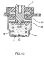
- FIG. 10 illustrates a liquid seal type fluid-filled mount according to another embodiment of the present invention, in which a movable damping unit 30 for high frequency vibrations and a fixed damping unit 35 for lateral impact are used.
- the liquid seal type fluid-filled mount with the above-described structure has damping effect for high frequency vibrations. Further, high damping effect may be realized even when the lateral impact is added.
- the damping unit of the fixed damping unit is made of a rubber material in the above embodiments, limitations are not imposed on such a material.
- the sidewall of the cup-shaped housing 1 is tapered downward to have a small volume, it is not limited thereto.
- the movable damping plate is formed as a flat plate in the above embodiments.
- it is not limited thereto and may be formed as an inverted cup shape. In such a case, one end of the coil spring is placed into an inside of the inverted cup.
- At least one long groove may be formed along an outer circumferential surface of the movable damping plate of the inverted cup.
- the coil spring is used as a spring member in the above embodiments.
- various springs such as conical coil springs or cylinders made of elastic materials, for example, rubber, may be used.
- a section of a coiled wire of the coil spring may show rectangular or square shape as well as a circular shape (as shown in FIG. 1 ).
- the top end and the bottom end of the coil spring are held by concave portions (as shown in FIG. 1 ), but may be held by convex portions.
- the flexible seal cap should be formed to a thickness not to be deformed by fluid-pressure applied from the high viscosity fluid in the above embodiments.
- fabrics may be added to have resistance against strain to deform or the thickness of the cap may be thin.
- the top end of the cup-shaped housing is caulked along an edge, whereby the flange of the cup-shaped housing, the flange portion of the holder of the fixed damping unit and the flange portion of the holder of the flexible seal cap are integrated, sealed fluid-tight.
- the above-mentioned flange and flange portions may be integrated by a welding process and the like, in addition to the caulking process.
- the fluid is injected through the fluid injection hole formed at the bottom of the cup-shaped housing in the above embodiments.
- an air vent (not shown) for exhausting air from the sealed housing may be further formed to the bottom of the cup-shaped housing in addition to the injection hole.
- the high viscosity fluid may be injected into the housing sealed fluid-tight, and, at the same time, air may be exhausted from the above sealed housing to the outside.
- the stud may be formed with an opening in an axial direction, through which the high viscosity fluid may be injected.
- the high viscosity fluid may be filled into the cup-shaped housing under vacuum first and then the housing may be sealed by the flexible seal cap.
- the present invention provides a liquid seal type fluid-filled mount which is advantageous in terms of high damping effect caused by the use of a movable damping plate and a fixing damping plate, and a large vertical stroke may be obtained caused by a flexible seal cap mounted to an upper end of a stud for prevention of fluid leakage and a spring installed at a lower end of the stud while the movable damping plate is placed between the spring and the stud.
- the flexible seal cap includes a cap body and a holder, whereby a top portion of the cup-shaped housing is simply sealed not to allow leakage of the fluid.
- a layered cap of the flexible seal cap functions to enlarge lateral strength against lateral impact.
- the movable damping plate is mounted to the lower portion of the stud to be slightly movable, thus easily damping high frequency vibrations.
- an inner surface of a central opening of the fixed damping unit comes into partial contact with an outer circumferential surface of the stud to be movable, to enlarge the strength against lateral impact.
- the central opening of the fixed damping unit may be formed in a tapered shape, thereby exhibiting high damping effect even though the stud is tilted to a side under inclined lateral impact.
Landscapes
- Engineering & Computer Science (AREA)
- General Engineering & Computer Science (AREA)
- Mechanical Engineering (AREA)
- Combined Devices Of Dampers And Springs (AREA)
Description
- The present invention relates to a liquid seal type fluid-filled mount as defined in the preamble of
claim 1 and comprising a movable damping plate and a fixed damping unit, which is advantageous in terms of enlarged vertical strokes and high damping effect. - As well known to those skilled in the art, a conventional liquid seal type fluid-filled mount, capable of enlarging vertical strokes, is disclosed in Japanese Patent Laid-open Publication No.
H7-127683 claim 1 is disclosed inUS-A-5 988 610 . - The liquid seal type fluid-filled mount disclosed in Japanese Patent Laid-open Publication No.
H7-127683 - A liquid seal type fluid-filled mount of a type mentioned as above can have a large vertical stroke and high damping effect.
- However, as for such a conventional liquid seal type fluid-filled mount, the elastic cylindrical body should be mounted at the top portion of the cup-shaped housing and the sleeve should be disposed inside the elastic cylindrical body. Further, in order to enclose a space between an inner surface of the sleeve and an outer surface of the stud, bellows should be integrally connected between a lower end of the elastic cylindrical body and the movable damping plate.
- Furthermore, the stud should be installed to be axially slidable in the sleeve.
- As explained above, the conventional liquid seal type fluid-filled mount has a complicated structure, with a service life of the bellows being short, and also risking possible leakage of high viscosity fluid.
- Accordingly, the object of the present invention is to provide a liquid seal type fluid-filled mount comprising a movable damping plate and a fixed damping unit.
- Another object of the present invention is to provide a liquid seal type fluid-filled mount that enables high damping effect.
- Yet another object of the present invention is to provide a liquid seal type fluid-filled mount that enables large strokes.
- Still another object of the present invention is to provide a liquid seal type fluid-filled mount with a simple structure in sealing a high viscosity fluid.
- A still further object of the present invention is to provide a liquid seal type fluid-filled mount with improved strength against lateral impact using a simple structure.
- A still further object of the present invention is to provide a liquid seal type fluid-filled mount capable of damping external high frequency vibrations using a simple structure.
- A still further object of the present invention is to provide a liquid seal type fluid-filled mount capable of obtaining high damping effect even though a stud is tilted by inclined lateral impact from outside.
- The above mentioned objects are achieved by the features defined in the characterizing part of
claim 1. The present invention is defined byclaim 1. - As for the liquid seal type fluid-filled mount of
claim 1, the second holder, has a flange portion and a cylindrical portion, and the cylindrical portion is vulcanized to an outer circumferential side of the cap body. - As for the liquid seal type fluid-filled mount of
claim - As for the liquid seal type fluid-filled mount of
claim - As for the liquid seal type fluid-filled mount of
claims - As for the liquid seal type fluid-filled mount, of
claims - As for the liquid seal type fluid-filled mount of
claims -
-
FIG. 1 is a sectional view of a liquid seal type fluid-filled mount, according to one embodiment of the present invention; -
FIG. 2 is a plan view of another embodiment of a movable damping plate in the liquid seal type fluid-filled mount shown inFIG. 1 ; -
FIG. 3 is a sectional view of a liquid seal type fluid-filled mount according to another embodiment of the present invention; -
FIG. 4 is a sectional view of a liquid seal type fluid-filled mount according to yet another embodiment of the present invention; -
FIG. 5 is a sectional view taken along the A1-A2 line shown inFIG. 4 ; -
FIG. 6 is a sectional view of a liquid seal type fluid-filled mount according to still other embodiment of the present invention; -
FIG. 7 is a sectional view of a liquid seal type fluid-filled mount according to another embodiment of the present invention; -
FIG. 8 is a view illustrating a damping operation shown inFIG. 7 ; -
FIG. 9 is a sectional view of a liquid seal type fluid-filled mount according to yet another embodiment of the present invention; and -
FIG. 10 is a sectional view of a liquid seal type fluid-filled mount according to still another embodiment of the present invention; - Reference will now be made in detail to the present preferred embodiments of the present invention.
-
FIG. 1 illustrates a liquid seal type fluid-filled mount according to one embodiment of the present invention in which thereference numeral 1 designates a cup-shaped housing. The cup-shaped housing 1 is disposed with aflange 1A and a caulked portion 1B at a top portion thereof, and afluid injection hole 1C for injectinghigh viscosity fluid 2 at a bottom portion thereof. In addition, a mounting-hole 1D is formed at theflange 1A. Astud 3 is disposed along a central axis of the cup-shaped housing 1, and a threaded-hole 3A for mounting thestud 3 to a target material is axially formed at an upper end of thestud 3. In addition, amovable damping plate 4 is mounted to a lower end of thestud 3 with aspring washer 5 and anut 6. Aflexible seal cap 7 is composed of acap body 8 and aholder 9. - The
cap body 8, is made of a rubber material being formed to a doughnut shape, and a center hole of the doughnut-shaped cap body 8 is vulcanized to an upper portion of thestud 3, sealed fluid-tight. In addition, theholder 9 is provided with acylindrical portion 9A and aflange portion 9B. Thecylindrical portion 9A of theholder 9 is vulcanized to an outer peripheral side of thecap body 8, sealed fluid-tight. Theflange portion 9B is formed with a mounting-hole 9C. - A fixed
damping unit 10 has acentral opening 10A at a center thereof and is provided with a dampingbody 11 and aholder 12. A second fluid passage is formed between an inner surface of thecentral opening 10A and an outer circumferential surface of thestud 3. - The damping
body 11, which is made of, for example, a rubber material, and thecentral opening 10A is located at a center thereof. Theholder 12 of the fixeddamping unit 10 has acylindrical portion 12A and a flange portion 12B and thedamping body 11 is vulcanized to thecylindrical portion 12A. - The flange portion 12B has a mounting-
hole 12C. - A
coil spring 13 is disposed between the bottom of the cup-shaped housing 1 and themovable damping plate 4. Thereference numeral 14 is a plug. Theplug body 14 is fitted into thefluid injection hole 1C formed at the bottom of the cup-shaped housing 1, sealed fluid-tight. - Further, the cup-
shaped housing 1 forms a liquid-seal type container with theflexible seal cap 7 andhigh viscosity fluid 2 is disposed therein. As such, thehigh viscosity fluid 2 may be poured into the sealedhousing 1 through thefluid injection hole 1C formed at the bottom of the cup-shapedhousing 1. - As for the damping operation of the liquid seal type fluid-filled mount, the
high viscosity fluid 2 passes through a first fluid passage formed between an inner circumferential surface of the cup-shapedhousing 1 and an outer circumferential surface of the movable dampingplate 4, thereby exhibiting damping effect. Further, thehigh viscosity fluid 2 passes through a second fluid passage formed between an inner surface of thecentral opening 10A of the fixed dampingunit 10 and the outer circumferential surface of thestud 3, thereby exhibiting additional damping effect which results in even higher damping effect. - The vertical stroke of the movable damping
plate 4 may be enlarged by a change in the design of theflexible seal cap 7 and thecoil spring 13. - Further, since a thickness (vertical height) of the fixed damping
unit 10 may be increased, the fixed dampingunit 10 may provide higher damping effect compared to a fixed damping unit with a thin plate. - The
cylindrical portion 9A of theholder 9 of theflexible seal cap 7, together with thecap body 8 made of a rubber material of thecylindrical portion 9A, functions as a stopper for a vibration-proof portion not shown in the figure. - Although the outer circumferential surface of the movable damping
plate 4 is formed to be smooth in the embodiment explained above, it may be formed with a plurality ofgrooves 4A, for example, 18grooves 4A as shown inFIG. 2 . -
FIG. 3 illustrates a liquid seal type fluid-filled mount according to another embodiment of the present invention, in which thereference numeral 20 designates a flexible seal cap. Theflexible seal cap 20 is provided with alayered cap 21 and aholder 22. The layeredcap 21 has threerubber rings bushes 21D and 21E, alternately vulcanized. An inner surface of therubber ring 21A is vulcanized to the top portion of thestud 3. - The
holder 22 includes acylindrical portion 22A and a flange portion 22B, in which thecylindrical portion 22A is vulcanized to therubber ring 21C. The flange portion 22B is formed with a mounting-hole 22C. - The
flexible seal cap 20 having the above setup is mounted fluid-tight at the top portion of the cup-shapedhousing 1 is as described inFIG. 1 . - The liquid seal type fluid-filled mount according to the embodiment of the present invention has damping effect as high as the liquid seal type fluid-filled mount according to the embodiment illustrated in
FIG. 1 . Even though being subjected to high lateral impact, that is, inclined impact, thestud 3 is not easily tilted due to theflexible seal cap 20. Thus there is no reduction of damping effect. - Although the layered
cap 21 comprises alternately layered three rubber rings and two bushes, N rubber rings and N-1 bushes may be alternately layered. -
FIG. 4 illustrates a liquid seal type fluid-filled mount according to yet other embodiment of the present invention, andFIG. 5 illustrates a section of the line A1-A2 shown inFIG. 4 . In the figure, a sliding-type fixed dampingunit 25 includes a dampingbody 26 and aholder 27. - As shown in
FIGs. 4 and5 , a part of an inner surface of the dampingbody 26 comes into contact with the outer circumferential surface of thestud 3 and also to be slidable, and, for example, sixfluid passages 26A being formed. - The liquid seal type fluid-filled mount having the above setup according to the above-described embodiment of the present invention is advantageous in terms of high damping effect and high lateral strength against lateral impact.
-
FIG. 6 illustrates a liquid seal type fluid-filled mount according to another embodiment of the present invention, in which thereference numeral 30 designates a movable damping unit for high frequency vibrations. The movable dampingunit 30 for high frequency vibrations consists of a movable dampingplate 31, acollar 32 and asupport plate 33. The movable dampingplate 31, in the state of being slightly movable in a vertical direction, is mounted to the lower end of thestud 3 by thesupport plate 33, aspring washer 5 and anut 6, while thecollar 32 is disposed between the dampingplate 31 and thesupport plate 33. - When such a liquid seal type fluid-filled mount is subjected to external high-frequency vibrations, the movable damping
plate 31 is slightly moved to only a height of thecollar 32, thereby damping and absorbing high-frequency vibrations. - The
support plate 33 is necessarily formed with a plurality of central openings (not shown), to the extent of not being deformed by the spring force of thecoil spring 13. -
FIG. 7 illustrates a liquid seal type fluid-filled mount according to another embodiment of the present invention, in which thereference numeral 35 designates a fixed damping unit for lateral impact. The fixed dampingunit 35 for lateral impact includes a dampingbody 36 and theholder 12. - The damping
body 35 is made of a rubber material, and a center thereof is formed with atapered opening 36A. Theholder 12 includes acylindrical portion 12A and a flange portion 12B as shown inFIG. 1 . - A second fluid passage is formed between the inner surface of the
tapered opening 36A and the outer circumferential surface of thestud 3. - Turning now to
FIG. 8 , there is shown an action of the liquid seal type fluid-filled mount, in particular, a damping operation when thestud 3 is tilted to a side by high lateral impact. - When the
stud 3 is tilted by increased lateral impact, the movable dampingplate 4 is also inclined. Thus, a first fluid passage formed by the dampingplate 4 is deformed, and as a result, the damping effect may decrease. - However, even though the
stud 3 is tilted, the second fluid passage is ensured between thestud 3 and thetapered opening 36A of the fixed damping unit forlateral impact 35, thus exhibiting a predetermined damping effect. Hence, damping effect by the second fluid passage does not decrease and total damping effect is maintained at a desired level. -
FIG. 9 illustrates a sectional view of a liquid seal type fluid-filled mount according to another embodiment of the present invention, in which a layeredcap 21 of aflexible cap 20 and a fixed dampingunit 35 for lateral impact are used. - The liquid seal type fluid-filled mount of the above-described structure has advantages such as high damping effect and high lateral strength against lateral impact may be obtained.
-
FIG. 10 illustrates a liquid seal type fluid-filled mount according to another embodiment of the present invention, in which a movable dampingunit 30 for high frequency vibrations and a fixed dampingunit 35 for lateral impact are used. - The liquid seal type fluid-filled mount with the above-described structure has damping effect for high frequency vibrations. Further, high damping effect may be realized even when the lateral impact is added.
- Although the damping unit of the fixed damping unit is made of a rubber material in the above embodiments, limitations are not imposed on such a material.
- Further, although the sidewall of the cup-shaped
housing 1 is tapered downward to have a small volume, it is not limited thereto. - Furthermore, the movable damping plate is formed as a flat plate in the above embodiments. However, it is not limited thereto and may be formed as an inverted cup shape. In such a case, one end of the coil spring is placed into an inside of the inverted cup.
- In addition, at least one long groove may be formed along an outer circumferential surface of the movable damping plate of the inverted cup.
- The coil spring is used as a spring member in the above embodiments. However, various springs, such as conical coil springs or cylinders made of elastic materials, for example, rubber, may be used.
- A section of a coiled wire of the coil spring may show rectangular or square shape as well as a circular shape (as shown in
FIG. 1 ). - In the above embodiments, the top end and the bottom end of the coil spring are held by concave portions (as shown in
FIG. 1 ), but may be held by convex portions. - The flexible seal cap should be formed to a thickness not to be deformed by fluid-pressure applied from the high viscosity fluid in the above embodiments. However, fabrics may be added to have resistance against strain to deform or the thickness of the cap may be thin.
- Also, in the above-described embodiment, the top end of the cup-shaped housing is caulked along an edge, whereby the flange of the cup-shaped housing, the flange portion of the holder of the fixed damping unit and the flange portion of the holder of the flexible seal cap are integrated, sealed fluid-tight. However, the above-mentioned flange and flange portions may be integrated by a welding process and the like, in addition to the caulking process.
- When the high viscosity fluid is filled into the housing sealed for prevention of fluid leakage and comprising the cup-shaped housing and the flexible seal cap, the fluid is injected through the fluid injection hole formed at the bottom of the cup-shaped housing in the above embodiments. However, an air vent (not shown) for exhausting air from the sealed housing may be further formed to the bottom of the cup-shaped housing in addition to the injection hole. Thereby, the high viscosity fluid may be injected into the housing sealed fluid-tight, and, at the same time, air may be exhausted from the above sealed housing to the outside. Thus a period of time required to inject the fluid may be considerably shortened. Moreover, the stud may be formed with an opening in an axial direction, through which the high viscosity fluid may be injected. In addition, the high viscosity fluid may be filled into the cup-shaped housing under vacuum first and then the housing may be sealed by the flexible seal cap.
- As described above, the present invention provides a liquid seal type fluid-filled mount which is advantageous in terms of high damping effect caused by the use of a movable damping plate and a fixing damping plate, and a large vertical stroke may be obtained caused by a flexible seal cap mounted to an upper end of a stud for prevention of fluid leakage and a spring installed at a lower end of the stud while the movable damping plate is placed between the spring and the stud.
- In addition, the flexible seal cap includes a cap body and a holder, whereby a top portion of the cup-shaped housing is simply sealed not to allow leakage of the fluid. A layered cap of the flexible seal cap functions to enlarge lateral strength against lateral impact.
- Further, the movable damping plate is mounted to the lower portion of the stud to be slightly movable, thus easily damping high frequency vibrations.
- Furthermore, an inner surface of a central opening of the fixed damping unit comes into partial contact with an outer circumferential surface of the stud to be movable, to enlarge the strength against lateral impact. Also, the central opening of the fixed damping unit may be formed in a tapered shape, thereby exhibiting high damping effect even though the stud is tilted to a side under inclined lateral impact.
Claims (7)
- A liquid seal type fluid-filled mount, comprising:a cup-shaped housing (1) having a flange (1A) provided with a mounting hole;a stud (3) with a threaded hole (3A) provided at an upper end thereof; the stud being disposed along a central axis of the cup-shaped housing (1) so as to be positioned in a central opening of a fixed damping unit (10, 35);a flexible seal cap (7,20) providing a fluid-tight seal between the upper end of the stud (3) and the cup-shaped housing(1) the flexible seal cap (7, 20) having a cap body (8) and a holder (4), the cap body (8) being made of a rubber material being formed to a doughnut shape having a centre hole;a high viscosity liquid (2) for filling a chamber formed by the cup-shaped housing (1) and the flexible seal cap (7, 20),a movable damping plate(4, 31) mounted to a lower end of the stud (3) and placed In the high viscosity fluid;a fixed damping unit (10, 35) provided with a damping body (11) made of an elastic material, said fixed damping unit (10, 35) having a doughnut-shape, fixed between the flexible seal cap (7,20) and the movable damping plate (4. 31) and placed in the high viscosity fluid, the fixed damping unit (10, 35) including a first holder (12),a spring (13) disposed between a bottom of the cup-shaped housing (1) and the movable damping plate (4, 31);a first fluid passage formed between an inner circumferential surface of the cup-shaped housing (1) and an outer circumferential surface of the movable damping plate (4, 31) to exhibit a damping effect; anda second fluid passage formed between an inner surface of the central opening (10A) of the fixed damping unit (10) and an outer circumferential surface of the stud (3), wherein the high viscosity fluid passes through the second fluid passage to exhibit an additional damping effectcharacterized in that the first holder (12) has a first cylindrical portion (12A) vulcanised to and embedded in the damping body (11) and a first flange portion (12B), and in that the centre hole of the cap body (8) is vulcanized to an upper portion of the stud (3), sealed fluid-tight.
- A liquid seal type fluid-filled mount according to claim 1,
wherein the flexible seal cap (7) comprisesa cap body (8), made of a rubber material having a doughnut-shape, andthe second holder (9), has a second flange portion (9B) and a second cylindrical portion (9A), the second cylindrical portion (9A) being vulcanized to an outer circumferential side of the cap body (8). - A liquid seal type fluid-filled mount according to claim 1,
wherein the flexible seal cap (20) comprises:a layered cap (21), andthe second holder (22) has a second flange portion (22B) and a second cylindrical portion (22A),wherein the second cylindrical portion (22A) is vulcanized to an outer circumferential side of the layered cap (21) and the layered cap has a number N of elastic materials, such as rubber rings, being formed into a cylindrical shape, and N-1 number of bushes; the elastic materials and the bushes are being alternately layered. - A liquid seal type fluid-filled mount according to any preceding claim,
wherein said elastic material is rubber having a predetermined thickness. - A fluid-filled mount according to any preceding claim,
wherein the central opening (10A) formed at a centre of the fixed damping unit (10, 35) has at least one groove at an inner surface thereof. - A liquid seal type fluid-filled mount according to any preceding claim,
wherein the central opening (10A) formed at the centre of the fixed damping unit (35) has a tapered opening (36A). - A liquid seal type fluid-filled mount according to any preceding claim,
wherein the movable damping plate(31) is disposed at the lower end of the stud (3) so that the plate (31) is slightly movable in a vertical direction.
Applications Claiming Priority (3)
| Application Number | Priority Date | Filing Date | Title |
|---|---|---|---|
| KR1020020023931A KR20030085715A (en) | 2002-05-01 | 2002-05-01 | Fluid-filled mount |
| KR2002023931 | 2002-05-01 | ||
| PCT/JP2003/005477 WO2003093697A1 (en) | 2002-05-01 | 2003-04-28 | Liquid seal type mount device |
Publications (4)
| Publication Number | Publication Date |
|---|---|
| EP1500846A1 EP1500846A1 (en) | 2005-01-26 |
| EP1500846A4 EP1500846A4 (en) | 2005-06-01 |
| EP1500846B1 EP1500846B1 (en) | 2008-07-02 |
| EP1500846B2 true EP1500846B2 (en) | 2014-04-09 |
Family
ID=29398450
Family Applications (1)
| Application Number | Title | Priority Date | Filing Date |
|---|---|---|---|
| EP03720976.4A Expired - Lifetime EP1500846B2 (en) | 2002-05-01 | 2003-04-28 | Hydraulic mount |
Country Status (7)
| Country | Link |
|---|---|
| US (2) | US7604223B2 (en) |
| EP (1) | EP1500846B2 (en) |
| JP (2) | JP4313599B2 (en) |
| KR (1) | KR20030085715A (en) |
| CN (3) | CN101514735B (en) |
| DE (1) | DE60321904D1 (en) |
| WO (1) | WO2003093697A1 (en) |
Families Citing this family (26)
| Publication number | Priority date | Publication date | Assignee | Title |
|---|---|---|---|---|
| KR20030085715A (en) * | 2002-05-01 | 2003-11-07 | 가부시키가이샤 후코쿠 | Fluid-filled mount |
| US20080296816A1 (en) * | 2004-10-29 | 2008-12-04 | Fukoku Co., Ltd | Vibration-Isolating Support Device |
| US20090014930A1 (en) * | 2005-11-15 | 2009-01-15 | Fukoku Co., Ltd | Liquid sealed mount and method of assembling the same |
| JP4976056B2 (en) * | 2006-06-05 | 2012-07-18 | 株式会社ブリヂストン | Vibration isolator |
| US20090289472A1 (en) * | 2008-04-02 | 2009-11-26 | Catanzarite David M | Construction vehicle cab suspension mount |
| EP2257717A2 (en) * | 2008-04-02 | 2010-12-08 | Lord Corporation | A construction vehicle cab suspension mount |
| CN102149941B (en) * | 2008-09-17 | 2013-10-16 | 东洋橡胶工业株式会社 | Liquid-sealed anti-vibration device |
| IT1393550B1 (en) * | 2009-04-03 | 2012-04-27 | Lord Corp | FORK ELEVATOR WITH ANTI-VIBRATION DEVICE |
| JP5225923B2 (en) | 2009-04-16 | 2013-07-03 | 東洋ゴム工業株式会社 | Liquid-filled vibration isolator |
| JP5336299B2 (en) * | 2009-08-21 | 2013-11-06 | 株式会社ブリヂストン | Vibration isolator |
| DE102009044005A1 (en) | 2009-09-15 | 2011-03-24 | Contitech Luftfedersysteme Gmbh | Spring-damping element |
| CN102069848B (en) * | 2009-11-19 | 2013-04-24 | 本田技研工业株式会社 | Mounting structure of subframe and manufacturing method of elastic assembly of mounting sub-frame of vehicle |
| WO2011114643A1 (en) * | 2010-03-19 | 2011-09-22 | 株式会社ブリヂストン | Liquid-sealed vibration control device, and method for producing same |
| GB2486499A (en) * | 2010-12-17 | 2012-06-20 | Perkinelmer Ltd | Anti-vibration foot portions for spectroscopic instruments |
| JP5198605B2 (en) * | 2011-03-11 | 2013-05-15 | 東洋ゴム工業株式会社 | Liquid-filled vibration isolator |
| CN102494078A (en) * | 2011-12-28 | 2012-06-13 | 常州市东海橡胶厂有限公司 | High-energy consumption viscoelastic silicone oil cabin vibration damper |
| KR20150053978A (en) | 2012-09-10 | 2015-05-19 | 가부시키가이샤 후코쿠 | Liquid filled mount |
| EP3074658B1 (en) * | 2013-11-25 | 2020-03-18 | LORD Corporation | Damping fluid devices, systems and methods |
| CN103742586A (en) * | 2013-12-26 | 2014-04-23 | 柳州正菱集团有限公司 | Excavator cab damper designing method |
| JP2015194241A (en) * | 2014-03-25 | 2015-11-05 | 株式会社フコク | Liquid filled mount |
| JP2015183805A (en) * | 2014-03-25 | 2015-10-22 | 株式会社フコク | Liquid enclosed mount |
| CN104141732B (en) * | 2014-07-03 | 2016-08-24 | 株洲时代新材料科技股份有限公司 | A kind of compound vibration-damper and manufacture method, combined vibration-damping method |
| US10570980B2 (en) * | 2016-05-23 | 2020-02-25 | Vibracoustic North America L.P. | Particle damper system and method |
| CN109095421A (en) * | 2018-10-23 | 2018-12-28 | 广州达意隆包装机械股份有限公司 | A kind of fluid-tight Allocating Circle system and method for bottle placer |
| US11339553B2 (en) | 2020-04-23 | 2022-05-24 | Deere & Company | Cab viscous mount |
| US12338871B2 (en) * | 2021-06-02 | 2025-06-24 | Vibracoustic Usa, Inc. | Hydraulic mount assembly and method |
Citations (3)
| Publication number | Priority date | Publication date | Assignee | Title |
|---|---|---|---|---|
| US5310168A (en) † | 1989-07-27 | 1994-05-10 | Tokai Rubber Industries, Ltd. | Fluid-filled cylindrical elastic mount having annular fluid chamber with constant cross sectional area over the entire circumference |
| US5707048A (en) † | 1994-02-15 | 1998-01-13 | Fukoku Co., Ltd. | Vibration dampening device with an elastic body and viscous liquid |
| JPH11210807A (en) † | 1998-01-20 | 1999-08-03 | Fukoku Co Ltd | High-viscosity liquid-filled mounting device |
Family Cites Families (28)
| Publication number | Priority date | Publication date | Assignee | Title |
|---|---|---|---|---|
| US1650742A (en) * | 1924-08-20 | 1927-11-29 | John V Rowan | Shock absorber |
| US3721417A (en) * | 1971-04-09 | 1973-03-20 | Lord Corp | Elastomeric combination shock and vibration isolator |
| JPS5910438Y2 (en) * | 1979-01-17 | 1984-04-02 | アイシン精機株式会社 | engine mount device |
| JPS58221032A (en) * | 1982-06-18 | 1983-12-22 | Tokico Ltd | cylinder device |
| JPS6184430A (en) * | 1984-09-29 | 1986-04-30 | Honda Motor Co Ltd | Anti-vibration support device |
| DE3808996A1 (en) * | 1988-03-17 | 1989-09-28 | Metzeler Gmbh | HYDRAULIC DAMPING TWO CHAMBER - ENGINE MOUNT |
| DE3835384A1 (en) * | 1988-10-18 | 1990-04-19 | Freudenberg Carl Fa | RUBBER BEARING |
| JP2861460B2 (en) * | 1991-04-10 | 1999-02-24 | 豊田合成株式会社 | Liquid filled vibration isolator |
| JPH0510373A (en) * | 1991-07-08 | 1993-01-19 | Bridgestone Corp | Vibration-proof device |
| DE4335510A1 (en) * | 1992-10-31 | 1994-05-05 | Volkswagen Ag | Elastic bearing for vehicle vibrating drive - has limited play allowed for at coupling point to vehicle drive |
| US5498060A (en) * | 1993-06-11 | 1996-03-12 | Kabushiki Kaisha Komatsu Seisakusho | Floor frame supporting structure for construction machines |
| JP3084544B2 (en) * | 1993-10-28 | 2000-09-04 | 株式会社フコク | Liquid-filled mounting device |
| JP3526117B2 (en) * | 1994-11-07 | 2004-05-10 | 株式会社小松製作所 | Liquid filled suspension |
| DE19543239A1 (en) * | 1995-11-20 | 1997-05-22 | Wolf Woco & Co Franz J | camp |
| JPH09166174A (en) * | 1995-12-15 | 1997-06-24 | Nok Megurasutikku Kk | Liquid sealing type mount |
| JPH1092784A (en) | 1996-09-10 | 1998-04-10 | Toshiba Microelectron Corp | Wafer processing apparatus and wafer processing method |
| JPH10148233A (en) * | 1996-09-20 | 1998-06-02 | Sumitomo Metal Ind Ltd | Liquid filled mount and axle box support device for railway vehicle using the same |
| US6279693B1 (en) * | 1998-02-26 | 2001-08-28 | Kasgro Rail Corp. | Friction dampener particularly adapted to railway vehicle motion control |
| CN1236074A (en) * | 1998-05-19 | 1999-11-24 | 卡尔·弗罗伊登伯格公司 | Hydraulic support |
| US6279593B1 (en) * | 1999-01-15 | 2001-08-28 | Hie Sheppard | Electric steam trap system and method of draining condensate |
| JP2000025658A (en) * | 1999-06-07 | 2000-01-25 | Fukoku Co Ltd | Liquid mount rubber mount |
| ES2232606T3 (en) * | 2000-02-23 | 2005-06-01 | Woco Avs Gmbh | HYDRAULIC BEARING. |
| JP4505152B2 (en) * | 2001-02-02 | 2010-07-21 | 株式会社小松製作所 | Anti-vibration mounting device |
| JP3957983B2 (en) | 2001-03-01 | 2007-08-15 | 大日本スクリーン製造株式会社 | Substrate developing device |
| JP4368071B2 (en) * | 2001-06-04 | 2009-11-18 | 株式会社小松製作所 | Liquid filled mount |
| JP2003049893A (en) * | 2001-08-06 | 2003-02-21 | Komatsu Ltd | Liquid-filled mount |
| JP4764578B2 (en) * | 2001-09-12 | 2011-09-07 | 株式会社小松製作所 | Liquid-filled mount mounted between the work vehicle cab and body frame |
| KR20030085715A (en) * | 2002-05-01 | 2003-11-07 | 가부시키가이샤 후코쿠 | Fluid-filled mount |
-
2002
- 2002-05-01 KR KR1020020023931A patent/KR20030085715A/en not_active Ceased
-
2003
- 2003-03-11 JP JP2003112150A patent/JP4313599B2/en not_active Expired - Fee Related
- 2003-04-28 DE DE60321904T patent/DE60321904D1/en not_active Expired - Lifetime
- 2003-04-28 CN CN2009100014889A patent/CN101514735B/en not_active Expired - Fee Related
- 2003-04-28 CN CNB038144735A patent/CN100465472C/en not_active Expired - Fee Related
- 2003-04-28 CN CN2009100014893A patent/CN101514736B/en not_active Expired - Fee Related
- 2003-04-28 EP EP03720976.4A patent/EP1500846B2/en not_active Expired - Lifetime
- 2003-04-28 WO PCT/JP2003/005477 patent/WO2003093697A1/en not_active Ceased
-
2004
- 2004-10-28 US US10/974,835 patent/US7604223B2/en not_active Expired - Fee Related
-
2008
- 2008-10-06 JP JP2008259547A patent/JP5081782B2/en not_active Expired - Fee Related
-
2009
- 2009-09-03 US US12/553,709 patent/US7997566B2/en not_active Expired - Fee Related
Patent Citations (3)
| Publication number | Priority date | Publication date | Assignee | Title |
|---|---|---|---|---|
| US5310168A (en) † | 1989-07-27 | 1994-05-10 | Tokai Rubber Industries, Ltd. | Fluid-filled cylindrical elastic mount having annular fluid chamber with constant cross sectional area over the entire circumference |
| US5707048A (en) † | 1994-02-15 | 1998-01-13 | Fukoku Co., Ltd. | Vibration dampening device with an elastic body and viscous liquid |
| JPH11210807A (en) † | 1998-01-20 | 1999-08-03 | Fukoku Co Ltd | High-viscosity liquid-filled mounting device |
Also Published As
| Publication number | Publication date |
|---|---|
| JP2003322198A (en) | 2003-11-14 |
| WO2003093697A1 (en) | 2003-11-13 |
| US7997566B2 (en) | 2011-08-16 |
| DE60321904D1 (en) | 2008-08-14 |
| JP4313599B2 (en) | 2009-08-12 |
| CN101514735B (en) | 2011-10-12 |
| US20050056980A1 (en) | 2005-03-17 |
| US20090322002A1 (en) | 2009-12-31 |
| KR20030085715A (en) | 2003-11-07 |
| US7604223B2 (en) | 2009-10-20 |
| CN101514736B (en) | 2011-08-03 |
| EP1500846A1 (en) | 2005-01-26 |
| JP2009002526A (en) | 2009-01-08 |
| CN101514736A (en) | 2009-08-26 |
| CN100465472C (en) | 2009-03-04 |
| JP5081782B2 (en) | 2012-11-28 |
| CN101514735A (en) | 2009-08-26 |
| CN1662755A (en) | 2005-08-31 |
| EP1500846A4 (en) | 2005-06-01 |
| EP1500846B1 (en) | 2008-07-02 |
Similar Documents
| Publication | Publication Date | Title |
|---|---|---|
| EP1500846B2 (en) | Hydraulic mount | |
| EP0173273B1 (en) | Vibration isolating apparatus | |
| US7637486B2 (en) | Very high damping body mount, subframe mount or engine mount with bolt-through construction | |
| CN101981342B (en) | Vibration-damping device | |
| US8177201B2 (en) | Very high damping mount with bolt-through construction | |
| JP3629483B2 (en) | Switchable liquid-filled vibration isolator | |
| US4505461A (en) | Fluid-filled engine mount device | |
| US6485005B1 (en) | Hydraulic mount with gas spring supported decoupler | |
| US6224045B1 (en) | Vibration damping device having fluid chambers on opposite sides of partition structure having movable rubber plate | |
| WO2004090373A1 (en) | Liquid sealing type vibration control device | |
| JPWO2003001079A1 (en) | Liquid-filled vibration isolator | |
| JP3682813B2 (en) | Liquid-filled mount and assembly method thereof | |
| KR20170029677A (en) | Engine-mount | |
| US20020089104A1 (en) | Hydraulic bearing background of the invention | |
| JP4257997B2 (en) | Liquid filled mounting device | |
| JP3560390B2 (en) | Liquid filled type vibration damping device | |
| JPH07269638A (en) | Liquid seal-type vibration isolating device | |
| JP2009275748A (en) | Vibration control device and its manufacturing method | |
| JP2005076664A (en) | Liquid-filled vibration isolator | |
| JPH09177871A (en) | Vibration control device | |
| JP2009293746A (en) | Vibration insulation device | |
| JPH07197988A (en) | Vibration control device |
Legal Events
| Date | Code | Title | Description |
|---|---|---|---|
| PUAI | Public reference made under article 153(3) epc to a published international application that has entered the european phase |
Free format text: ORIGINAL CODE: 0009012 |
|
| 17P | Request for examination filed |
Effective date: 20041027 |
|
| AK | Designated contracting states |
Kind code of ref document: A1 Designated state(s): DE FR IT |
|
| A4 | Supplementary search report drawn up and despatched |
Effective date: 20050420 |
|
| RTI1 | Title (correction) |
Free format text: HYDRAULIC MOUNT |
|
| GRAP | Despatch of communication of intention to grant a patent |
Free format text: ORIGINAL CODE: EPIDOSNIGR1 |
|
| GRAS | Grant fee paid |
Free format text: ORIGINAL CODE: EPIDOSNIGR3 |
|
| GRAA | (expected) grant |
Free format text: ORIGINAL CODE: 0009210 |
|
| AK | Designated contracting states |
Kind code of ref document: B1 Designated state(s): DE FR IT |
|
| REF | Corresponds to: |
Ref document number: 60321904 Country of ref document: DE Date of ref document: 20080814 Kind code of ref document: P |
|
| PLBI | Opposition filed |
Free format text: ORIGINAL CODE: 0009260 |
|
| PLAX | Notice of opposition and request to file observation + time limit sent |
Free format text: ORIGINAL CODE: EPIDOSNOBS2 |
|
| 26 | Opposition filed |
Opponent name: HANO, CHRISTIAN Effective date: 20090327 |
|
| PLAF | Information modified related to communication of a notice of opposition and request to file observations + time limit |
Free format text: ORIGINAL CODE: EPIDOSCOBS2 |
|
| PLBB | Reply of patent proprietor to notice(s) of opposition received |
Free format text: ORIGINAL CODE: EPIDOSNOBS3 |
|
| APBM | Appeal reference recorded |
Free format text: ORIGINAL CODE: EPIDOSNREFNO |
|
| APBP | Date of receipt of notice of appeal recorded |
Free format text: ORIGINAL CODE: EPIDOSNNOA2O |
|
| APAH | Appeal reference modified |
Free format text: ORIGINAL CODE: EPIDOSCREFNO |
|
| APBQ | Date of receipt of statement of grounds of appeal recorded |
Free format text: ORIGINAL CODE: EPIDOSNNOA3O |
|
| APBU | Appeal procedure closed |
Free format text: ORIGINAL CODE: EPIDOSNNOA9O |
|
| PUAH | Patent maintained in amended form |
Free format text: ORIGINAL CODE: 0009272 |
|
| STAA | Information on the status of an ep patent application or granted ep patent |
Free format text: STATUS: PATENT MAINTAINED AS AMENDED |
|
| 27A | Patent maintained in amended form |
Effective date: 20140409 |
|
| AK | Designated contracting states |
Kind code of ref document: B2 Designated state(s): DE FR IT |
|
| REG | Reference to a national code |
Ref country code: DE Ref legal event code: R102 Ref document number: 60321904 Country of ref document: DE |
|
| REG | Reference to a national code |
Ref country code: DE Ref legal event code: R102 Ref document number: 60321904 Country of ref document: DE Effective date: 20140409 |
|
| REG | Reference to a national code |
Ref country code: FR Ref legal event code: PLFP Year of fee payment: 14 |
|
| REG | Reference to a national code |
Ref country code: FR Ref legal event code: PLFP Year of fee payment: 15 |
|
| PGFP | Annual fee paid to national office [announced via postgrant information from national office to epo] |
Ref country code: FR Payment date: 20170327 Year of fee payment: 15 |
|
| PG25 | Lapsed in a contracting state [announced via postgrant information from national office to epo] |
Ref country code: FR Free format text: LAPSE BECAUSE OF NON-PAYMENT OF DUE FEES Effective date: 20180430 |
|
| PGFP | Annual fee paid to national office [announced via postgrant information from national office to epo] |
Ref country code: IT Payment date: 20190419 Year of fee payment: 17 Ref country code: DE Payment date: 20190416 Year of fee payment: 17 |
|
| REG | Reference to a national code |
Ref country code: DE Ref legal event code: R119 Ref document number: 60321904 Country of ref document: DE |
|
| PG25 | Lapsed in a contracting state [announced via postgrant information from national office to epo] |
Ref country code: DE Free format text: LAPSE BECAUSE OF NON-PAYMENT OF DUE FEES Effective date: 20201103 |
|
| PG25 | Lapsed in a contracting state [announced via postgrant information from national office to epo] |
Ref country code: IT Free format text: LAPSE BECAUSE OF NON-PAYMENT OF DUE FEES Effective date: 20200428 |