EP1500748B1 - Dispositif auxiliaire de balayage pour balayeuses de rues - Google Patents
Dispositif auxiliaire de balayage pour balayeuses de rues Download PDFInfo
- Publication number
- EP1500748B1 EP1500748B1 EP03029360A EP03029360A EP1500748B1 EP 1500748 B1 EP1500748 B1 EP 1500748B1 EP 03029360 A EP03029360 A EP 03029360A EP 03029360 A EP03029360 A EP 03029360A EP 1500748 B1 EP1500748 B1 EP 1500748B1
- Authority
- EP
- European Patent Office
- Prior art keywords
- sweeper
- arm
- sheath
- sweeping
- operator
- Prior art date
- Legal status (The legal status is an assumption and is not a legal conclusion. Google has not performed a legal analysis and makes no representation as to the accuracy of the status listed.)
- Expired - Lifetime
Links
- 241001417527 Pempheridae Species 0.000 title claims abstract description 51
- 238000010408 sweeping Methods 0.000 title claims abstract description 39
- 238000004140 cleaning Methods 0.000 title claims abstract description 10
- XLYOFNOQVPJJNP-UHFFFAOYSA-N water Substances O XLYOFNOQVPJJNP-UHFFFAOYSA-N 0.000 claims abstract description 13
- 238000004804 winding Methods 0.000 claims description 5
- 150000003839 salts Chemical class 0.000 claims description 4
- 230000008878 coupling Effects 0.000 claims description 3
- 238000010168 coupling process Methods 0.000 claims description 3
- 238000005859 coupling reaction Methods 0.000 claims description 3
- 239000004698 Polyethylene Substances 0.000 claims description 2
- 238000013016 damping Methods 0.000 claims description 2
- 230000005611 electricity Effects 0.000 claims description 2
- 229910052736 halogen Inorganic materials 0.000 claims description 2
- 150000002367 halogens Chemical class 0.000 claims description 2
- -1 polyethylene Polymers 0.000 claims description 2
- 229920000573 polyethylene Polymers 0.000 claims description 2
- 238000005507 spraying Methods 0.000 claims description 2
- 239000000725 suspension Substances 0.000 claims description 2
- 238000005406 washing Methods 0.000 claims description 2
- 239000002699 waste material Substances 0.000 description 5
- 238000010276 construction Methods 0.000 description 2
- 230000003068 static effect Effects 0.000 description 2
- 244000007853 Sarothamnus scoparius Species 0.000 description 1
- 238000005452 bending Methods 0.000 description 1
- 239000000463 material Substances 0.000 description 1
- 230000004048 modification Effects 0.000 description 1
- 238000012986 modification Methods 0.000 description 1
- 230000001360 synchronised effect Effects 0.000 description 1
Images



Classifications
-
- E—FIXED CONSTRUCTIONS
- E01—CONSTRUCTION OF ROADS, RAILWAYS, OR BRIDGES
- E01H—STREET CLEANING; CLEANING OF PERMANENT WAYS; CLEANING BEACHES; DISPERSING OR PREVENTING FOG IN GENERAL CLEANING STREET OR RAILWAY FURNITURE OR TUNNEL WALLS
- E01H1/00—Removing undesirable matter from roads or like surfaces, with or without moistening of the surface
- E01H1/10—Hydraulically loosening or dislodging undesirable matter; Raking or scraping apparatus ; Removing liquids or semi-liquids e.g., absorbing water, sliding-off mud
- E01H1/101—Hydraulic loosening or dislodging, combined or not with mechanical loosening or dislodging, e.g. road washing machines with brushes or wipers
- E01H1/103—Hydraulic loosening or dislodging, combined or not with mechanical loosening or dislodging, e.g. road washing machines with brushes or wipers in which the soiled loosening or washing liquid is removed, e.g. by suction
-
- E—FIXED CONSTRUCTIONS
- E01—CONSTRUCTION OF ROADS, RAILWAYS, OR BRIDGES
- E01H—STREET CLEANING; CLEANING OF PERMANENT WAYS; CLEANING BEACHES; DISPERSING OR PREVENTING FOG IN GENERAL CLEANING STREET OR RAILWAY FURNITURE OR TUNNEL WALLS
- E01H1/00—Removing undesirable matter from roads or like surfaces, with or without moistening of the surface
- E01H1/08—Pneumatically dislodging or taking-up undesirable matter or small objects; Drying by heat only or by streams of gas; Cleaning by projecting abrasive particles
- E01H1/0863—Apparatus loosening or removing the dirt by blowing and subsequently dislodging it at least partially by suction ; Combined suction and blowing nozzles
Definitions
- the present invention relates to a sweeping aiding device for municipal street cleaning sweepers.
- street sweepers are conventionally used for cleaning municipal streets and comprise a plurality of motor driven cleaning brushes, specifically designed for sweeping the street surface and collecting dirt therefrom.
- the mentioned street sweepers are adapted to operate in an optimum manner if the street being cleaned is free and not obstructed by obstacles.
- a walking operator provided with a broom or other sweeping instrument, can collect said dirt at a region which can be accessed by the sweeper brushes.
- the document EP-A-0 683 278 discloses a sweeping aiding device comprising a windable sheath bearing a sweeping lance.
- the main object of the present invention is to provide a sweeping aiding device, specifically designed for solving the above mentioned problems, which device also allows a walking operator to easily and quickly collect dirt and waste materials to direct the latter to the sweeper cleaning brushes, without requiring any great physical effort by the operator, and which can also be used for a long period.
- Yet another important object of the present invention is to provide such a sweeping aiding device which also allows to properly clean streets and sidewalks even in regions thereof occupied by parked vehicles, and this by aiding the cleaning operator by a safe, efficient and noiseless system which, in addition, can be also easily controlled.
- a sweeping aiding device to be applied to municipal street sweepers, according to claim 1.
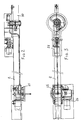
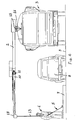
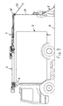
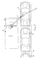
- the sweeping aiding device which has been generally indicated by the reference number 1, comprises a semiautomatic two articulated-joint arm, comprising a first arm segment 2 fixed at the middle region of the street sweeper 3 above the front portion of the tilting casing 4 thereof, through a first articulated joint 11.
- the above mentioned arm is of a self-moving type, i.e. it can be driven in a plane parallel to the ground, and arranged at a level greater than the maximum height of the sweeper.
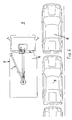
- the sweeping operation is performed by using pressurized water delivered from the street sweeping machine and, to that end, the sweeping aiding device ends with a sheath 13 supplying and supporting a sweeping lance 5.
- Said sweeping lance is driven by a walking operator 6, and allow to displace dirt and waste materials from the sidewalks 7 and from the bottom of the cars or vehicles 8 parked at the central portion of the street 9, from which said dirt and waste materials are collected by the sweeper, which in the meanwhile washes the street surface.
- the articulated arm as is shown, comprises a second segment 10 coupled to the first segment 2 by a second articulated joint 12.
- the two arm segments 2 and 10 in the maximally extended condition thereof, have a length larger than six meters, but a specifically designed system for winding and automatically recovering the sheath 13 allows the operator to move away, if necessary, by other three meters from the sweeper.
- the lance 5 supporting sheath 13 slides, at the end portion of the arm, in a special supporting element, of a joystick type, which automatically drives the arm segment, thereby providing an operator tracking length reserve, independently from the movement direction of the operator.
- the walking operator can perform the dirt and waste material removal operation, without considering the position of the sweeper arm.
- the sheath 13 ends with an electric connector and a water quick fitting, allowing, as the sweeping aiding device is in an idle condition above the sweeper, to disconnect the lance 5 for storing it at any other desired location.
- the supporting sheath 13 will be automatically wound within the arm segment 10 and will be bracketed on a side of the casing or box 4.
- the sheath 13 is wound, by a specifically designed winding system, inside the second segment 10 on a cable holder chain 19 coupled to the aiding shoes 20, which can slide at the top in a polyethylene guiding element 21.
- the sheath 13 projects from the second arm segment 10 through the end portion 18 comprising a control system for controlling the position and movement of said sheath, said control system comprising two potentiometers 23 and 24, each of which is provided with small rollers 25, arranged in respective orthogonal planes, thereby to transmit an electric signal to the control central unit controlling the servomotors 26 and 27 which respectively drive the first and second articulated joints.
- said potentiometers can detect or sense the operator moving speed, so as to properly control the servomotors of the articulated arm to properly track or follow the moving operator.
- a spotlight element having a halogen lamp, mounted on the end portion 18 of the second arm segment 10, will allow the sweeper to also operate in a night period, by diffusely illuminating from the top the working region.
- the two arm segments are compasses-like closed, and are bracketed on the sweeper 3 by an automatic safety locking system.
- the sweeping aiding device will be held inside the sweeper perimeter thereby meeting the maximum height values provided by the Street Code.
- the sweeping aiding device is adapted to indifferently operate on both sides of the sweeper.
- a selector or switch element, arranged on the cab button panel of the sweeper will allow to select the working side and then, the system controlling softer will prevent any further movements on the other side of the sweeper.
- the rotary movements of the two arm segments are motor driven.
- Torque limiting elements together with damping rubber section elements, arranged on the sides of the arms, will protect the equipment from accidental impacts.
- the device bearing construction 15 is coupled, by a removable coupling means, to a fixing or attachment plate 16, rigid with the sweeper casing or box 4.
- said sweeping aiding device attachment plate 16 is removably coupled, by a coupling bracket, to the front portion of the casing 4 of the sweeper 3.
- the bearing construction can be subjected to the following loads:
- the lance gripper 17 of the lance has integrated therein an on/off joystick electric control to allow the operator to adjust, through a knob control valve, the flow rate of the water being sprayed from the lance 5.
- the device further comprises an independent electric panel, meeting the related CE standards, provided for driving and controlling the sweeper; it comprises: a PLC for controlling the operating and safety logic circuits; I/O cards for managing the transmitted signals; and the electric motor drives.
- the device comprises moreover an independent pushbutton panel, mounted on the sweeper cab, and including the following control pushbuttons: on/off selector; emergency pushbutton; arm extending and withdrawing selector or switch; a selector for operating either at the right or at the left of the truck; a small panel for necessary alarms; an alarm reset pushbutton; and a lighting system on/off selector or switch.
- the driver and walking operator can continuously communicate through a radio-wave interphone system, with an earphone for the walking operator and in a voiced manner for the driver, thereby providing a highly synchronous cooperating of the driver and operator.
- the sweeper can also comprise, onboard, the following provisions, as necessary for operating the sweeping aiding device: electricity 24 V; voltage 24+/-15% Vcc; and useful power 0.85 kW, as necessary for power supplying the arm motors, lighting system and electronic cabinet.
- Pressurized water is advantageously filtered and free of suspensions and has a rated pressure from 60 to 100 bars (adjustable), a maximum pressure of 110 bars and a maximum flowrate of 900 dm 3 /h, for water supplying the water spraying lance.
- the sweeping aiding device can also perform, by small modifications, even a cleaning function, by using an air blower, having a 24 Vcc electric motor, to be coupled to the sheath in place of the sweeping lance, and can also be electrically supplied by the sheath.
- the device can also be applied on a tank truck and can be used for washing streets and sidewalks, since it would have available great amounts of water.
- the device according to the invention can also be applied to a salt delivery truck, thereby delivering salt on the sidewalks and under the parked vehicles, under snow and ice condition.
- the invention provides a sweeping aiding device allowing to sweep and wash streets and sidewalks even in regions occupied by parked vehicles, aiding the operator through the use of a safe, efficient, noiseless and easily manoeuvrable system.
- the used materials, as well as the contingent size and shapes can be any, depending on requirements.
Landscapes
- Engineering & Computer Science (AREA)
- Architecture (AREA)
- Civil Engineering (AREA)
- Structural Engineering (AREA)
- Cleaning In General (AREA)
- Machines For Laying And Maintaining Railways (AREA)
- Automatic Cycles, And Cycles In General (AREA)
- Harvester Elements (AREA)
- Cleaning Of Streets, Tracks, Or Beaches (AREA)
- Brushes (AREA)
Claims (20)
- Dispositif d'aide au nettoyage (1) devant être appliqué aux nettoyeuses municipales, ledit dispositif comprenant un bras articulé (2, 10), qui peut être couplé à une nettoyeuse (3), ledit bras articulé (2, 10) étant un bras articulé servocontrôlé semi-automatique comprenant un premier segment de bras (2) devant être fixé au milieu de ladite nettoyeuse (3), au-dessus d'une portion avant d'une carrosserie basculante (4) de celle-ci, par l'intermédiaire d'une première rotule articulée (11), ledit bras articulé (2, 10) étant auto-mobile dans un plan parallèle au sol, agencé à un niveau supérieur à la hauteur maximum de ladite nettoyeuse (3), ledit bras articulé (2, 10) comprenant un second segment de bras (10) couplé au premier segment de bras (10), par l'intermédiaire d'une seconde rotule articulée (12), caractérisé en ce que lesdits deux segments de bras (2, 10) dans un état d'extension maximum, ont une longueur supérieure à six mètres, et en ce que le dispositif d'aide au nettoyage comprend en outre un tuyau enroulable (13) portant, au niveau d'une portion de son extrémité, une lance de nettoyage (5) conçue pour fournir de l'eau sous pression et pour être tenue par un opérateur à pied (6), un système de rangement et d'enroulage automatique étant fourni pour enrouler ledit tuyau (13) pour permettre audit opérateur (6) de s'éloigner ladite nettoyeuse (3) de trois mètres supplémentaires, ledit tuyau (13) étant supporté, de manière coulissante, au niveau de la portion d'extrémité du bras dans un élément de type joystick entraînant automatiquement les segments de bras (2, 10), en fournissant ainsi une longueur de réserve pour permettre audit opérateur (6) de suivre facilement ladite nettoyeuse (3) selon n'importe quelle direction.
- Dispositif selon la revendication 1, caractérisé en ce que ledit tuyau (13) se termine par un connecteur électrique et un raccord rapide sur les conduites d'eau, ce qui permet, lorsque ledit dispositif est dans un état de repos sur la nettoyeuse (3), de déconnecter ladite lance (5) et de la stocker dans n'importe quel autre emplacement souhaité, ledit tuyau (13) étant automatiquement enroulé dans ledit second segment de bras (10) et étant ensuite placé sur un crochet sur une paroi latérale de la carrosserie de la nettoyeuse (4).
- Dispositif selon la revendication 1, caractérisé en ce que ledit tuyau (13) est enroulable par ledit système d'enroulage à l'intérieur du second segment de bras (10), sur une chaîne de tenue de câble (19) associée à des patins coulissants 20 qui peuvent coulisser sur leur partie supérieure dans un élément de guidage en polyéthylène (21).
- Dispositif selon la revendication 1, caractérisé en ce que ledit second segment de bras (10), a une section ovale, dans laquelle des conduites de câbles électriques (22) sont agencées.
- Dispositif selon la revendication 1 caractérisé en ce que ledit tuyau (13) fait saillie à partir dudit second segment de bras (10), à travers sa portion d'extrémité comprenant un système de commande permettant de commander la position et le mouvement dudit tuyau (13), ledit système de commande comprenant deux potentiomètres (23, 24), chacun incluant des rouleaux (25) agencés dans des plans respectivement orthogonaux, pour transmettre un signal électrique à une unité centrale de commande commandant le fonctionnement des servomoteurs (26, 27), afin d'entraîner respectivement la première rotule articulée (11) et la seconde rotule articulée (12), et grâce à quoi, alors que ledit opérateur à pieds (6) se déplace dans n'importe quelle direction, il entraîne ledit tuyau (13) dans une direction définie de manière non équivoque, qui est précisément définie par les mouvements rotatifs des deux dits potentiomètres (23, 24).
- Dispositif selon la revendication 5, caractérisé en ce que lesdits potentiomètres (23, 24) sont conçus pour détecter la vitesse de déplacement de l'opérateur, de façon à faire fonctionner lesdits servomoteurs (26, 27) du bras articulé (2, 10) pour suivre le mouvement de l'opérateur.
- Dispositif selon la revendication 1, caractérisé en ce que ledit dispositif comprend, en outre, un élément d'éclairage incluant une lampe halogène, montée sur la portion d'extrémité du second segment de bras (10), et permettant que la nettoyeuse (3) soit utilisée également la nuit, ledit éclairage illuminant de manière diffuse la région de travail depuis le haut.
- Dispositif selon la revendication 1, caractérisé en ce que, dans leur position de repos ou d'attente, lesdits deux segments de bras articulés (2, 20) doivent être refermés comme des compas et placés sur un crochet sur la nettoyeuse (3), grâce à un système de blocage de sécurité automatique, de telle sorte que, dans cet agencement, la taille dudit dispositif est maintenue à l'intérieur du périmètre de la nettoyeuse, ce qui répond aux valeurs de hauteur maximum indiquées par le Code de la route.
- Dispositif selon la revendication 1, caractérisé en ce que ledit dispositif est conçu pour travailler indifféremment des deux côtés de la nettoyeuse.
- Dispositif selon la revendication 1, caractérisé en ce que ledit dispositif comprend en outre un sélecteur qui doit être agencé sur un tableau à boutons-poussoirs dans la cabine de pilotage, en permettant de sélectionner le côté du travail, pour permettre au logiciel commandant le système d'empêcher tout mouvement de l'autre côté de la nettoyeuse.
- Dispositif selon la revendication 1, caractérisé en ce que lesdits segments de bras (2, 10) sont entraînés en rotation automatiquement, et en ce que ledit dispositif comprend en outre des éléments limitant le couple qui, avec des éléments à section en caoutchouc d'amortissement agencés sur les côtés des bras, protègent le dispositif contre des chocs accidentels.
- Dispositif selon une ou plusieurs des revendications précédentes, caractérisé en ce que ledit dispositif comprend une structure porteuse qui peut être couplée de manière amovible à une plaque de fixation 16 à son tour couplée de manière amovible, par l'intermédiaire d'une console de couplage, à une portion avant de ladite carrosserie de la nettoyeuse (4).
- Dispositif selon la revendication 1, caractérisé en ce que ladite lance (5) a un système de poignée de lance (17) dans lequel est intégrée une commande électrique de joystick de marche/arrêt permettant à l'opérateur d'ajuster par l'intermédiaire d'un pommeau contrôlant une soupape, le débit d'eau à partir de ladite lance.
- Dispositif selon la revendication 1, caractérisé en ce que ledit dispositif comprend en outre un tableau électrique indépendant conçu pour piloter et commander la nettoyeuse (3), ledit tableau comprenant un PLC pour commander le circuit de logique de sécurité et de fonctionnement ; des cartes E/S pour la gestion des signaux et les manettes de commande du moteur électrique.
- Dispositif selon la revendication 1, caractérisé en ce que ledit dispositif comprend, en outre, un tableau à boutons-poussoirs indépendant, agencé dans la cabine de pilotage de la nettoyeuse et incluant les commandes suivantes : interrupteur de sélection marche/arrêt ; bouton-poussoir d'arrêt d'urgence ; sélecteur d'extension et de retrait du bras ; sélecteur permettant au dispositif de fonctionner soit sur la droite soit sur la gauche du camion de nettoyage ; tableau d'alarme ; bouton-poussoir de réinitialisation de l'alarme ; sélecteur de marche/arrêt de l'éclairage.
- Dispositif selon la revendication 1, caractérisé en ce que ledit dispositif comprend, en outre, comme devant être agencé à bord de ladite nettoyeuse (3), les services suivants permettant de faire fonctionner le dispositif d'aide au nettoyage : électricité 24 V ; tension 24 +/- 15 % en Vcc ; puissance utile 0,85 kW pour une alimentation électrique des moteurs du bras, le système d'éclairage et de l'armoire électrique.
- Dispositif selon une ou plusieurs des revendications précédentes, caractérisé en ce que la lance de pulvérisation (5) est conçue pour être alimentée par de l'eau sous pression qui a été filtrée et qui est exempte de suspensions et qui a une pression réglable entre 60 et 100 bars, une pression maximum de 110 bars et un débit maximum de 900 dm3/H.
- Dispositif selon une ou plusieurs des revendications précédentes, caractérisé en ce que ledit dispositif est également conçu pour fournir une fonction de nettoyage en utilisant une soufflante d'air, incluant un moteur électrique de 24 Vcc devant être couplé audit tuyau (13), à la place de ladite lance de nettoyage (5), et qui est alimenté en électricité par ledit tuyau (13).
- Dispositif selon une ou plusieurs des revendications précédentes, caractérisé en ce que ledit dispositif est conçu pour être appliqué sur un camion-citerne ayant de grandes quantités d'eau disponibles, et utilisé pour laver les rues et les trottoirs.
- Dispositif selon une ou plusieurs des revendications précédentes, caractérisé en ce que ledit dispositif est conçu pour être appliqué sur un camion épandeur de sel, pour épandre du sel sur les trottoirs et sous les véhicules en stationnement, dans des conditions climatiques de neige et de glace.
Applications Claiming Priority (2)
| Application Number | Priority Date | Filing Date | Title |
|---|---|---|---|
| ITMI20031459 | 2003-07-16 | ||
| IT001459A ITMI20031459A1 (it) | 2003-07-16 | 2003-07-16 | Dispositivo agevolatore di spazzamento, applicabile in particolare a motospazzatrici utilizzate nei servizi di nettezza urbana |
Publications (3)
| Publication Number | Publication Date |
|---|---|
| EP1500748A2 EP1500748A2 (fr) | 2005-01-26 |
| EP1500748A3 EP1500748A3 (fr) | 2005-08-24 |
| EP1500748B1 true EP1500748B1 (fr) | 2008-02-13 |
Family
ID=33485509
Family Applications (1)
| Application Number | Title | Priority Date | Filing Date |
|---|---|---|---|
| EP03029360A Expired - Lifetime EP1500748B1 (fr) | 2003-07-16 | 2003-12-19 | Dispositif auxiliaire de balayage pour balayeuses de rues |
Country Status (5)
| Country | Link |
|---|---|
| EP (1) | EP1500748B1 (fr) |
| AT (1) | ATE386168T1 (fr) |
| DE (1) | DE60319077T2 (fr) |
| ES (1) | ES2301751T3 (fr) |
| IT (1) | ITMI20031459A1 (fr) |
Families Citing this family (3)
| Publication number | Priority date | Publication date | Assignee | Title |
|---|---|---|---|---|
| ITMI20120079A1 (it) * | 2012-01-25 | 2013-07-26 | Amsa S P A Societa Per Azioni Con Socio Unico | Dispositivo agevolatore di spazzamento a bracci folli, particolarmente per motospazzatrici utilizzabili nei servizi di nettezza urbana. |
| DE102018008269A1 (de) | 2018-04-13 | 2019-10-17 | Hako Gmbh | Straßenkehrmaschine |
| EP4647554A1 (fr) | 2024-05-07 | 2025-11-12 | Ingegneri Associati Production S.r.l. | Dispositif pour faciliter le balayage de balayeuses de rues ou de machines à laver |
Family Cites Families (4)
| Publication number | Priority date | Publication date | Assignee | Title |
|---|---|---|---|---|
| DE2916012A1 (de) * | 1979-04-20 | 1980-10-30 | Porsche Ag | Fahrzeug zum reinigen von verparkten strassen, verkehrsflaechen o.dgl. nach dem servosaugprinzip |
| FR2626023B1 (fr) * | 1988-01-20 | 1994-05-06 | Euronov | Dispositif multifonctionnel de nettoiement et de traitement a distance des surfaces, articles et objets situes en bordure des voies de circulation |
| DE4417126C2 (de) * | 1994-05-16 | 1998-07-09 | Karl Wiedemann | Kanalreinigungsfahrzeug |
| ITMI20011832A1 (it) * | 2001-08-30 | 2003-03-02 | Amsa S P A Azienda Milanese Se | Dispositivo agevolatore di spazzamento, particolarmente per motospazzatrici utilizzate nei servizi di nettezza urbana |
-
2003
- 2003-07-16 IT IT001459A patent/ITMI20031459A1/it unknown
- 2003-12-19 ES ES03029360T patent/ES2301751T3/es not_active Expired - Lifetime
- 2003-12-19 EP EP03029360A patent/EP1500748B1/fr not_active Expired - Lifetime
- 2003-12-19 DE DE60319077T patent/DE60319077T2/de not_active Expired - Lifetime
- 2003-12-19 AT AT03029360T patent/ATE386168T1/de active
Also Published As
| Publication number | Publication date |
|---|---|
| ATE386168T1 (de) | 2008-03-15 |
| ES2301751T3 (es) | 2008-07-01 |
| DE60319077D1 (de) | 2008-03-27 |
| EP1500748A2 (fr) | 2005-01-26 |
| ITMI20031459A1 (it) | 2005-01-17 |
| DE60319077T2 (de) | 2009-02-05 |
| EP1500748A3 (fr) | 2005-08-24 |
Similar Documents
| Publication | Publication Date | Title |
|---|---|---|
| JP7381022B2 (ja) | 自動道路スイーパ、および上記道路スイーパの道路洗浄方法 | |
| US20050102778A1 (en) | Rotary broom attachment for traction vehicles | |
| CN204016192U (zh) | 智能拖地机 | |
| EP1500748B1 (fr) | Dispositif auxiliaire de balayage pour balayeuses de rues | |
| CN112627092B (zh) | 冲洗车 | |
| CA3015581C (fr) | Nettoyant pour planchers de grange | |
| WO2012061888A1 (fr) | Engin de déblayage | |
| CN106760627A (zh) | 一种智能机器人马路垃圾清扫车 | |
| CN112900333B (zh) | 自动行驶的清扫机器 | |
| US10689820B1 (en) | Surface cleaning machine for road construction | |
| EP0467269B1 (fr) | Véhicules de nettoyage | |
| KR100766315B1 (ko) | 보도 물청소장비 | |
| EP1970270B1 (fr) | Dispositif mobile de nettoyage | |
| KR102099219B1 (ko) | 세그웨이 기반의 탑승형 청소기 | |
| EP1288374B1 (fr) | Dispositif d'aide au balayage pour balayeuses | |
| CN110258421A (zh) | 一种市政工程用道路积水处理车 | |
| US7578885B2 (en) | Concrete/asphalt wet washing system | |
| KR200243436Y1 (ko) | 가이드레일 청소차 | |
| US10709104B2 (en) | Barn floor cleaner | |
| CN206299151U (zh) | 智能机器人马路垃圾清扫车 | |
| US4761016A (en) | Automatic vehicle with forwardly mounted tool assembly and steering system for guiding the tool assembly | |
| CN221422481U (zh) | 一种清雪去冰作业装置 | |
| CN222663296U (zh) | 清洗系统 | |
| CN210975677U (zh) | 一种公路路面及里程碑两用清洁装置 | |
| CA2344119C (fr) | Balayeuse de rue |
Legal Events
| Date | Code | Title | Description |
|---|---|---|---|
| PUAI | Public reference made under article 153(3) epc to a published international application that has entered the european phase |
Free format text: ORIGINAL CODE: 0009012 |
|
| AK | Designated contracting states |
Kind code of ref document: A2 Designated state(s): AT BE BG CH CY CZ DE DK EE ES FI FR GB GR HU IE IT LI LU MC NL PT RO SE SI SK TR |
|
| AX | Request for extension of the european patent |
Extension state: AL LT LV MK |
|
| PUAL | Search report despatched |
Free format text: ORIGINAL CODE: 0009013 |
|
| AK | Designated contracting states |
Kind code of ref document: A3 Designated state(s): AT BE BG CH CY CZ DE DK EE ES FI FR GB GR HU IE IT LI LU MC NL PT RO SE SI SK TR |
|
| AX | Request for extension of the european patent |
Extension state: AL LT LV MK |
|
| 17P | Request for examination filed |
Effective date: 20051014 |
|
| AKX | Designation fees paid |
Designated state(s): AT BE BG CH CY CZ DE DK EE ES FI FR GB GR HU IE IT LI LU MC NL PT RO SE SI SK TR |
|
| 17Q | First examination report despatched |
Effective date: 20060810 |
|
| 17Q | First examination report despatched |
Effective date: 20060810 |
|
| GRAP | Despatch of communication of intention to grant a patent |
Free format text: ORIGINAL CODE: EPIDOSNIGR1 |
|
| GRAS | Grant fee paid |
Free format text: ORIGINAL CODE: EPIDOSNIGR3 |
|
| GRAA | (expected) grant |
Free format text: ORIGINAL CODE: 0009210 |
|
| AK | Designated contracting states |
Kind code of ref document: B1 Designated state(s): AT BE BG CH CY CZ DE DK EE ES FI FR GB GR HU IE IT LI LU MC NL PT RO SE SI SK TR |
|
| REG | Reference to a national code |
Ref country code: GB Ref legal event code: FG4D |
|
| REG | Reference to a national code |
Ref country code: CH Ref legal event code: EP |
|
| REG | Reference to a national code |
Ref country code: IE Ref legal event code: FG4D |
|
| REF | Corresponds to: |
Ref document number: 60319077 Country of ref document: DE Date of ref document: 20080327 Kind code of ref document: P |
|
| REG | Reference to a national code |
Ref country code: CH Ref legal event code: NV Representative=s name: BOVARD AG PATENTANWAELTE |
|
| REG | Reference to a national code |
Ref country code: ES Ref legal event code: FG2A Ref document number: 2301751 Country of ref document: ES Kind code of ref document: T3 |
|
| PG25 | Lapsed in a contracting state [announced via postgrant information from national office to epo] |
Ref country code: FI Free format text: LAPSE BECAUSE OF FAILURE TO SUBMIT A TRANSLATION OF THE DESCRIPTION OR TO PAY THE FEE WITHIN THE PRESCRIBED TIME-LIMIT Effective date: 20080213 |
|
| PG25 | Lapsed in a contracting state [announced via postgrant information from national office to epo] |
Ref country code: SI Free format text: LAPSE BECAUSE OF FAILURE TO SUBMIT A TRANSLATION OF THE DESCRIPTION OR TO PAY THE FEE WITHIN THE PRESCRIBED TIME-LIMIT Effective date: 20080213 |
|
| ET | Fr: translation filed | ||
| PG25 | Lapsed in a contracting state [announced via postgrant information from national office to epo] |
Ref country code: SE Free format text: LAPSE BECAUSE OF FAILURE TO SUBMIT A TRANSLATION OF THE DESCRIPTION OR TO PAY THE FEE WITHIN THE PRESCRIBED TIME-LIMIT Effective date: 20080513 Ref country code: CZ Free format text: LAPSE BECAUSE OF FAILURE TO SUBMIT A TRANSLATION OF THE DESCRIPTION OR TO PAY THE FEE WITHIN THE PRESCRIBED TIME-LIMIT Effective date: 20080213 Ref country code: PT Free format text: LAPSE BECAUSE OF FAILURE TO SUBMIT A TRANSLATION OF THE DESCRIPTION OR TO PAY THE FEE WITHIN THE PRESCRIBED TIME-LIMIT Effective date: 20080714 Ref country code: DK Free format text: LAPSE BECAUSE OF FAILURE TO SUBMIT A TRANSLATION OF THE DESCRIPTION OR TO PAY THE FEE WITHIN THE PRESCRIBED TIME-LIMIT Effective date: 20080213 Ref country code: SK Free format text: LAPSE BECAUSE OF FAILURE TO SUBMIT A TRANSLATION OF THE DESCRIPTION OR TO PAY THE FEE WITHIN THE PRESCRIBED TIME-LIMIT Effective date: 20080213 |
|
| PG25 | Lapsed in a contracting state [announced via postgrant information from national office to epo] |
Ref country code: RO Free format text: LAPSE BECAUSE OF FAILURE TO SUBMIT A TRANSLATION OF THE DESCRIPTION OR TO PAY THE FEE WITHIN THE PRESCRIBED TIME-LIMIT Effective date: 20080213 |
|
| PLBE | No opposition filed within time limit |
Free format text: ORIGINAL CODE: 0009261 |
|
| STAA | Information on the status of an ep patent application or granted ep patent |
Free format text: STATUS: NO OPPOSITION FILED WITHIN TIME LIMIT |
|
| 26N | No opposition filed |
Effective date: 20081114 |
|
| PG25 | Lapsed in a contracting state [announced via postgrant information from national office to epo] |
Ref country code: EE Free format text: LAPSE BECAUSE OF FAILURE TO SUBMIT A TRANSLATION OF THE DESCRIPTION OR TO PAY THE FEE WITHIN THE PRESCRIBED TIME-LIMIT Effective date: 20080213 Ref country code: BG Free format text: LAPSE BECAUSE OF FAILURE TO SUBMIT A TRANSLATION OF THE DESCRIPTION OR TO PAY THE FEE WITHIN THE PRESCRIBED TIME-LIMIT Effective date: 20080513 |
|
| PG25 | Lapsed in a contracting state [announced via postgrant information from national office to epo] |
Ref country code: MC Free format text: LAPSE BECAUSE OF NON-PAYMENT OF DUE FEES Effective date: 20081231 Ref country code: CY Free format text: LAPSE BECAUSE OF FAILURE TO SUBMIT A TRANSLATION OF THE DESCRIPTION OR TO PAY THE FEE WITHIN THE PRESCRIBED TIME-LIMIT Effective date: 20080213 |
|
| PG25 | Lapsed in a contracting state [announced via postgrant information from national office to epo] |
Ref country code: IE Free format text: LAPSE BECAUSE OF NON-PAYMENT OF DUE FEES Effective date: 20081219 |
|
| PG25 | Lapsed in a contracting state [announced via postgrant information from national office to epo] |
Ref country code: LU Free format text: LAPSE BECAUSE OF NON-PAYMENT OF DUE FEES Effective date: 20081219 Ref country code: HU Free format text: LAPSE BECAUSE OF FAILURE TO SUBMIT A TRANSLATION OF THE DESCRIPTION OR TO PAY THE FEE WITHIN THE PRESCRIBED TIME-LIMIT Effective date: 20080814 |
|
| PG25 | Lapsed in a contracting state [announced via postgrant information from national office to epo] |
Ref country code: TR Free format text: LAPSE BECAUSE OF FAILURE TO SUBMIT A TRANSLATION OF THE DESCRIPTION OR TO PAY THE FEE WITHIN THE PRESCRIBED TIME-LIMIT Effective date: 20080213 |
|
| PG25 | Lapsed in a contracting state [announced via postgrant information from national office to epo] |
Ref country code: GR Free format text: LAPSE BECAUSE OF FAILURE TO SUBMIT A TRANSLATION OF THE DESCRIPTION OR TO PAY THE FEE WITHIN THE PRESCRIBED TIME-LIMIT Effective date: 20080514 |
|
| REG | Reference to a national code |
Ref country code: CH Ref legal event code: PFA Owner name: AMSA S.P.A. AZIENDA MILANESE SERVIZI AMBIENTALI Free format text: AMSA S.P.A. AZIENDA MILANESE SERVIZI AMBIENTALI#VIA OLGETTINA, 25#20132 MILANO (IT) -TRANSFER TO- AMSA S.P.A. AZIENDA MILANESE SERVIZI AMBIENTALI#VIA OLGETTINA, 25#20132 MILANO (IT) |
|
| PGFP | Annual fee paid to national office [announced via postgrant information from national office to epo] |
Ref country code: CH Payment date: 20121228 Year of fee payment: 10 |
|
| PGFP | Annual fee paid to national office [announced via postgrant information from national office to epo] |
Ref country code: AT Payment date: 20121219 Year of fee payment: 10 |
|
| PGFP | Annual fee paid to national office [announced via postgrant information from national office to epo] |
Ref country code: BE Payment date: 20121228 Year of fee payment: 10 |
|
| PGFP | Annual fee paid to national office [announced via postgrant information from national office to epo] |
Ref country code: NL Payment date: 20121219 Year of fee payment: 10 |
|
| BERE | Be: lapsed |
Owner name: AMSA S.P.A. AZIENDA MILANESE SERVIZI AMBIENTALI Effective date: 20131231 |
|
| REG | Reference to a national code |
Ref country code: NL Ref legal event code: V1 Effective date: 20140701 |
|
| REG | Reference to a national code |
Ref country code: CH Ref legal event code: PL |
|
| REG | Reference to a national code |
Ref country code: AT Ref legal event code: MM01 Ref document number: 386168 Country of ref document: AT Kind code of ref document: T Effective date: 20131219 |
|
| PG25 | Lapsed in a contracting state [announced via postgrant information from national office to epo] |
Ref country code: LI Free format text: LAPSE BECAUSE OF NON-PAYMENT OF DUE FEES Effective date: 20131231 Ref country code: CH Free format text: LAPSE BECAUSE OF NON-PAYMENT OF DUE FEES Effective date: 20131231 Ref country code: NL Free format text: LAPSE BECAUSE OF NON-PAYMENT OF DUE FEES Effective date: 20140701 Ref country code: BE Free format text: LAPSE BECAUSE OF NON-PAYMENT OF DUE FEES Effective date: 20131231 |
|
| PG25 | Lapsed in a contracting state [announced via postgrant information from national office to epo] |
Ref country code: AT Free format text: LAPSE BECAUSE OF NON-PAYMENT OF DUE FEES Effective date: 20131219 |
|
| REG | Reference to a national code |
Ref country code: FR Ref legal event code: PLFP Year of fee payment: 13 |
|
| REG | Reference to a national code |
Ref country code: FR Ref legal event code: PLFP Year of fee payment: 14 |
|
| REG | Reference to a national code |
Ref country code: FR Ref legal event code: PLFP Year of fee payment: 15 |
|
| PGFP | Annual fee paid to national office [announced via postgrant information from national office to epo] |
Ref country code: GB Payment date: 20221214 Year of fee payment: 20 Ref country code: FR Payment date: 20221214 Year of fee payment: 20 |
|
| PGFP | Annual fee paid to national office [announced via postgrant information from national office to epo] |
Ref country code: ES Payment date: 20230125 Year of fee payment: 20 |
|
| PGFP | Annual fee paid to national office [announced via postgrant information from national office to epo] |
Ref country code: IT Payment date: 20221223 Year of fee payment: 20 Ref country code: DE Payment date: 20230102 Year of fee payment: 20 |
|
| P01 | Opt-out of the competence of the unified patent court (upc) registered |
Effective date: 20230309 |
|
| P02 | Opt-out of the competence of the unified patent court (upc) changed |
Effective date: 20230414 |
|
| REG | Reference to a national code |
Ref country code: DE Ref legal event code: R071 Ref document number: 60319077 Country of ref document: DE |
|
| REG | Reference to a national code |
Ref country code: ES Ref legal event code: FD2A Effective date: 20231227 |
|
| REG | Reference to a national code |
Ref country code: GB Ref legal event code: PE20 Expiry date: 20231218 |
|
| PG25 | Lapsed in a contracting state [announced via postgrant information from national office to epo] |
Ref country code: GB Free format text: LAPSE BECAUSE OF EXPIRATION OF PROTECTION Effective date: 20231218 |
|
| PG25 | Lapsed in a contracting state [announced via postgrant information from national office to epo] |
Ref country code: ES Free format text: LAPSE BECAUSE OF EXPIRATION OF PROTECTION Effective date: 20231220 |
|
| PG25 | Lapsed in a contracting state [announced via postgrant information from national office to epo] |
Ref country code: GB Free format text: LAPSE BECAUSE OF EXPIRATION OF PROTECTION Effective date: 20231218 Ref country code: ES Free format text: LAPSE BECAUSE OF EXPIRATION OF PROTECTION Effective date: 20231220 |