EP1500540A1 - Open roof construction for a vehicle - Google Patents
Open roof construction for a vehicle Download PDFInfo
- Publication number
- EP1500540A1 EP1500540A1 EP04105057A EP04105057A EP1500540A1 EP 1500540 A1 EP1500540 A1 EP 1500540A1 EP 04105057 A EP04105057 A EP 04105057A EP 04105057 A EP04105057 A EP 04105057A EP 1500540 A1 EP1500540 A1 EP 1500540A1
- Authority
- EP
- European Patent Office
- Prior art keywords
- link
- ribs
- guide head
- roof construction
- open
- Prior art date
- Legal status (The legal status is an assumption and is not a legal conclusion. Google has not performed a legal analysis and makes no representation as to the accuracy of the status listed.)
- Granted
Links
Images


Classifications
-
- B—PERFORMING OPERATIONS; TRANSPORTING
- B60—VEHICLES IN GENERAL
- B60J—WINDOWS, WINDSCREENS, NON-FIXED ROOFS, DOORS, OR SIMILAR DEVICES FOR VEHICLES; REMOVABLE EXTERNAL PROTECTIVE COVERINGS SPECIALLY ADAPTED FOR VEHICLES
- B60J7/00—Non-fixed roofs; Roofs with movable panels, e.g. rotary sunroofs
- B60J7/02—Non-fixed roofs; Roofs with movable panels, e.g. rotary sunroofs of sliding type, e.g. comprising guide shoes
- B60J7/024—Non-fixed roofs; Roofs with movable panels, e.g. rotary sunroofs of sliding type, e.g. comprising guide shoes characterised by the height regulating mechanism of the sliding panel
-
- B—PERFORMING OPERATIONS; TRANSPORTING
- B60—VEHICLES IN GENERAL
- B60J—WINDOWS, WINDSCREENS, NON-FIXED ROOFS, DOORS, OR SIMILAR DEVICES FOR VEHICLES; REMOVABLE EXTERNAL PROTECTIVE COVERINGS SPECIALLY ADAPTED FOR VEHICLES
- B60J7/00—Non-fixed roofs; Roofs with movable panels, e.g. rotary sunroofs
- B60J7/02—Non-fixed roofs; Roofs with movable panels, e.g. rotary sunroofs of sliding type, e.g. comprising guide shoes
- B60J7/022—Sliding roof trays or assemblies
Definitions
- the invention relates to an open roof construction for a vehicle in accordance with the preamble of the independent claims.
- Open roof constructions of this kind are known in various versions thereof.
- the object of the invention is to provide an open roof construction which embodies an improved construction of the guide head.
- the invention comprises the characterizing features as defined in one or more of of the independent claims.
- Advantageous embodiments of the invention constitute the subject matter of the subclaims.
- the invention provides a guide head for the guideways which is remarkable for a smooth movement of the guide head along the link ribs.
- the engagement between guide head and link ribs allows minor misalignments without this leading to an accumulation of shearing forces. Production tolerances can be increased without this leading to undesirable play or endangering the functioning of the mechanism in any other manner.
- negative play will develop, which will quickly lead to in the required running fit as a result of the use of plastic material. Shearing forces are more precisely determined and wear characteristics are improved. The wear-in times are reduced.
- the drawings show a fixed roof 1 of a vehicle, such as a passenger car, which is provided with a roof opening 2 for receiving an open roof construction.
- the open roof construction includes a closure element 3 for selectively closing or at least partially releasing the roof opening 2.
- the closure element 3 is a rigid panel, in particular a transparent panel of glass or plastic material, but also other closure elements such as slats or a flexible cover are conceivable.
- a sliding-tilt roof is used, wherein panel 3 can be moved from the closed position in roof opening 2 (Figs. 4, 5), on the one hand to an upwardly and rearwardly sloping ventilating position (Fig. 1) and on the other hand downwards (Fig. 5) and subsequently rearwards to a position under the fixed roof 1.
- a spoiler roof or a tilt roof or the like are possible, however, such as a spoiler roof or a tilt roof or the like.
- panel 3 is fitted with an operating mechanism 4 at both edges extending in the longitudinal direction of the open roof construction, which operating mechanisms each include a link slide 5 in this embodiment, which is slidably accommodated in a guideway of a guide rail 6.
- Said guide rail 6 is mounted on or forms part of a stationary part (not shown), for example a frame, which is attached to the fixed roof 1 of the vehicle.
- the guide rails 6 extend along the longitudinally extending edges of the roof opening 2 and possibly rearwards thereof.
- Part of the operating mechanism 4 is made up of a link 7, which is attached to the underside of panel 3, near the respective longitudinal edge, and that to a stiffening frame 8 thereof.
- a link 7 At its front end link 7 is fitted with a sliding shoe 9, which is slidably accommodated in associated grooves in guide rail 6, and which also functions as the front hinge for panel 3.
- Link slide 5 comprises two pairs of sliding shoes 10, which project laterally and which guide link slide 5 upon its movement in vertical direction in guide rail 6.
- Both link slide 5 and link plate 7 include guideways in the form of laterally projecting ribs 11, 12, wherein ribs 11 are formed on the lower edge of link plate 7 and extend away from each other, whilst ribs 12 are formed on the upper side of vertical walls 13, 14 of the link slide and extend towards each other.
- Link slide 5 and link plate 7 are formed of die-cut and flanged metal plates.
- Link ribs 11, 12 are formed thereon by encapsulating flanges formed on the edge of the metal plates of link plate 7 and link slide 5 in plastic by means of an injection moulding technique.
- a guide head 15 is in engagement with all ribs 11 and 12, and to that end it engages between the vertical walls 13, 14 of link slide 5 and round link plate 7.
- the interspace between the ribs 12 of link slide 5 is larger than the spacing between the outside surfaces of the two ribs 11 of link plate 7, so that link plate 7 can at least partially be accommodated between walls 13, 14 of link slide 5 in a lowermost position of panel 3.
- Guide head 15 is formed on the free end of an arm 16, which is pivotally connected by means of a pivot 17, to a driving slide 18 (Fig. 1), which is drivingly connected to a drive unit, such as an electric motor, a hand crank or the like, via a pressure-rigid driving cable or the like.
- a drive unit such as an electric motor, a hand crank or the like
- Link slide 5 is stationary during said pivoting.
- the driving slide is locked in position with respect to link slide 5, after which the entire operating mechanism 4 and panel 3 will move rearwards as one unit upon further rearward movement of the driving slide.
- Guide head 15 comprises a lower portion, which extends between vertical walls 13 and 14 of link slide 5 and which engages ribs 12 of link slide 5 from the inside.
- guide head 15 includes a pair of opposed grooves 19 facing away from each other, in which the ribs 12 can be slidably accommodated, so that guide head 15 can slide along ribs 12 and follow the path defined by ribs 12.
- the upper part of guide head 15 is adapted for engaging round the ribs 11 of link plate 7, and to that end guide head 15 includes two opposed grooves 20 facing towards each other, whose bottom walls continue via a central portion 21, whilst the upper walls of grooves 20 are formed by cams 22, which leave a space between them for passing link plate 7.
- the grooves do not have straight upper and lower walls in their longitudinal direction, but the upper and lower walls of grooves 19 and 20 diverge widely from a central portion.
- the ribs 11 and 12 can be received in grooves 19 and 20, respectively, at different angles, such that there is no play in at least one locationin grooves 19, 20, which location can vary in dependence on the angle between guide head 15 and the rib 11, 12 in question.
- the height of the ribs 11 and 12 can vary along the length thereof in dependence on the angle which the guide head 15 includes with the ribs 11, 12 in question at a specific location.
- the upper and lower surfaces of ribs 11, 12 extend substantially horizontally in transverse direction.
- Fig. 4 furthermore shows that the upper wall of the grooves 20 and the lower wall of cams 22 does not extend horizontally in transverse direction, either, but slopes upwards from the lateral opening of grooves 20, in this case at an angle of approx. 2 - 10 ⁇ with respect to the horizontal. Also the bottom walls of grooves 20 slope slightly upwards from central portion 21. The height of grooves 20 is thereby such that ribs 11 are accommodated in grooves 20 with some play in vertical direction at some distance from the lateral opening.
- a spring element 23 is provided, which includes a central lip 24 and two outer lips 25, which are interconnected and which consist of curved parts of spring steel.
- Central lip 24 is positioned between the central portion 21 of guide head 15 and the underside of ribs 11, whilst the outer lips 25 is positioned between the respective upper wall of grooves 19 and the upper side of ribs 12.
- the convex portion of lips 24, 25 abuts against the respective rib 11, 12.
- the spring force eliminates any play between guide head 15 and ribs 11, 12, whilst a certain tolerance is provided by the manner in which ribs 11, 12 are accommodated in grooves 20, 19.
- link plate 7 a certain slope of link plate 7, for example caused by a varying convexity of the closure element 3, is allowable on account of the oblique upper walls of grooves 20 and the space at the lower side of grooves 20 and the sloping lower walls thereof. Also in lateral direction sufficient play is present between ribs 11 and grooves 20 so as to offset any tolerances. According to the invention larger production tolerances are allowable without affecting the functioning of the operating mechanism. Also when the ribs 12 do not run entirely synchronously to link slide 5 in longitudinal direction, for example due to a slight shift of the two parts of which the link slide 5 is built up, this can be offset without any problem, without excessive frictional forces, by the guide head.
- a factor that plays a role thereby is that the slope of the ribs 12 with respect to the guide rail 6 is not very large, so that a movement in longitudinal direction of the two ribs 12 with respect to each other will not result in large differences in height in a specific cross-section.
- Fig. 5 shows an alternative embodiment of the open roof construction according to the invention, wherein spring element 23 has been left out and an elevation 26 has been formed in the central portion 21 of guide head 15, which elevation presses against the underside of ribs 11 and against which the underside of ribs 11 can abut at slightly varying angles so as to offset any obliqueness of link plate 7. Due to the construction of ribs 11, 12 and guide head 15, a rattle-free guidance without excessive frictional forces, with guide head 15 being worn in quickly, can be achieved also in those case where no spring element 23 is used. This is made possible by the line contacts and the negative play between ribs 11, 12 and the guide head.
- the ribs are preferably made of POM with molybdenum sulphide as an additive, which is conducive to smooth running.
- the driving element can also be implemented with other types of open roof constructions, such as tilt roofs and spoiler roofs, louvred roofs and the like.
- open roof constructions such as tilt roofs and spoiler roofs, louvred roofs and the like.
- the link slide may be stationary and actually form part of the stationary part of the open roof construction.
Landscapes
- Engineering & Computer Science (AREA)
- Mechanical Engineering (AREA)
- Body Structure For Vehicles (AREA)
- Vehicle Interior And Exterior Ornaments, Soundproofing, And Insulation (AREA)
Abstract
Description
- The invention relates to an open roof construction for a vehicle in accordance with the preamble of the independent claims.
- Open roof constructions of this kind are known in various versions thereof.
- The object of the invention is to provide an open roof construction which embodies an improved construction of the guide head.
- In order to accomplish that objective, the invention comprises the characterizing features as defined in one or more of of the independent claims. Advantageous embodiments of the invention constitute the subject matter of the subclaims.
- The invention provides a guide head for the guideways which is remarkable for a smooth movement of the guide head along the link ribs. The engagement between guide head and link ribs allows minor misalignments without this leading to an accumulation of shearing forces. Production tolerances can be increased without this leading to undesirable play or endangering the functioning of the mechanism in any other manner. In case of incorrect alignment of the link ribs in the longitudinal direction of the panel, negative play will develop, which will quickly lead to in the required running fit as a result of the use of plastic material. Shearing forces are more precisely determined and wear characteristics are improved. The wear-in times are reduced.
- The invention will now be explained in more detail with reference to the drawings, which schematically show an exemplary embodiment of the invention.
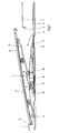
- Fig. 1 is a longitudinal sectional view of the embodiment of the open roof construction according to the invention, showing the closure element in an open ventilating position.
- Fig. 2 is a larger-scale perspective view of an operating mechanism on one side of the open roof construction of Fig. 1, showing the closure element in the closed position.
- Fig. 3 is a perspective, exploded view of the operating mechanism of Fig. 2.
- Fig. 4 is a larger-scale view, partially in cross-section, of the open roof construction of Fig. 1 along line IV-IV in Fig. 2.
- Fig. 5 is a sectional view corresponding to Fig. 4 of an alternative embodiment of the operating mechanism of the open roof construction according to the invention.
-
- The open roof construction as shown in the drawings constitutes the subject matter of further copending patent applications of the same date, whose contents are incorporated herein by reference thereto.
- The drawings show a
fixed roof 1 of a vehicle, such as a passenger car, which is provided with a roof opening 2 for receiving an open roof construction. The open roof construction includes aclosure element 3 for selectively closing or at least partially releasing theroof opening 2. In this embodiment theclosure element 3 is a rigid panel, in particular a transparent panel of glass or plastic material, but also other closure elements such as slats or a flexible cover are conceivable. In the illustrated embodiment a sliding-tilt roof is used, whereinpanel 3 can be moved from the closed position in roof opening 2 (Figs. 4, 5), on the one hand to an upwardly and rearwardly sloping ventilating position (Fig. 1) and on the other hand downwards (Fig. 5) and subsequently rearwards to a position under thefixed roof 1. Also other embodiments are possible, however, such as a spoiler roof or a tilt roof or the like. - In order to enable the movements of
panel 3,panel 3 is fitted with anoperating mechanism 4 at both edges extending in the longitudinal direction of the open roof construction, which operating mechanisms each include alink slide 5 in this embodiment, which is slidably accommodated in a guideway of aguide rail 6. Saidguide rail 6 is mounted on or forms part of a stationary part (not shown), for example a frame, which is attached to thefixed roof 1 of the vehicle. Theguide rails 6 extend along the longitudinally extending edges of the roof opening 2 and possibly rearwards thereof. - Part of the
operating mechanism 4 is made up of alink 7, which is attached to the underside ofpanel 3, near the respective longitudinal edge, and that to astiffening frame 8 thereof. At itsfront end link 7 is fitted with asliding shoe 9, which is slidably accommodated in associated grooves inguide rail 6, and which also functions as the front hinge forpanel 3.Link slide 5 comprises two pairs ofsliding shoes 10, which project laterally and whichguide link slide 5 upon its movement in vertical direction inguide rail 6. - Both
link slide 5 andlink plate 7 include guideways in the form of laterally projectingribs ribs 11 are formed on the lower edge oflink plate 7 and extend away from each other, whilstribs 12 are formed on the upper side ofvertical walls Link slide 5 andlink plate 7 are formed of die-cut and flanged metal plates.Link ribs link plate 7 andlink slide 5 in plastic by means of an injection moulding technique. Aguide head 15 is in engagement with allribs vertical walls link slide 5 andround link plate 7. The interspace between theribs 12 oflink slide 5 is larger than the spacing between the outside surfaces of the tworibs 11 oflink plate 7, so thatlink plate 7 can at least partially be accommodated betweenwalls link slide 5 in a lowermost position ofpanel 3. -
Guide head 15 is formed on the free end of anarm 16, which is pivotally connected by means of apivot 17, to a driving slide 18 (Fig. 1), which is drivingly connected to a drive unit, such as an electric motor, a hand crank or the like, via a pressure-rigid driving cable or the like. By moving theguide head 15, which acts as a wedge betweenlink slide 5 andlink plate 7, with respect toguideways link plate 7 and thuspanel 3 will be pivoted aboutpivot 9.Link slide 5 is stationary during said pivoting. In the lower pivoted position ofpanel 3 the driving slide is locked in position with respect tolink slide 5, after which theentire operating mechanism 4 andpanel 3 will move rearwards as one unit upon further rearward movement of the driving slide. - The construction of the guide head, which is preferably made of aluminium, is clearly shown in Figs. 3 and 4.
Guide head 15 comprises a lower portion, which extends betweenvertical walls link slide 5 and which engagesribs 12 oflink slide 5 from the inside. To this end,guide head 15 includes a pair ofopposed grooves 19 facing away from each other, in which theribs 12 can be slidably accommodated, so thatguide head 15 can slide alongribs 12 and follow the path defined byribs 12. The upper part ofguide head 15 is adapted for engaging round theribs 11 oflink plate 7, and to thatend guide head 15 includes twoopposed grooves 20 facing towards each other, whose bottom walls continue via acentral portion 21, whilst the upper walls ofgrooves 20 are formed bycams 22, which leave a space between them for passinglink plate 7. - As is shown in Figs. 1 and 3, the grooves do not have straight upper and lower walls in their longitudinal direction, but the upper and lower walls of
grooves ribs grooves locationin grooves guide head 15 and therib ribs guide head 15 includes with theribs ribs - Fig. 4 furthermore shows that the upper wall of the
grooves 20 and the lower wall ofcams 22 does not extend horizontally in transverse direction, either, but slopes upwards from the lateral opening ofgrooves 20, in this case at an angle of approx. 2 - 10□ with respect to the horizontal. Also the bottom walls ofgrooves 20 slope slightly upwards fromcentral portion 21. The height ofgrooves 20 is thereby such thatribs 11 are accommodated ingrooves 20 with some play in vertical direction at some distance from the lateral opening. In order to prevent rattling ofguide head 15round ribs spring element 23 is provided, which includes acentral lip 24 and twoouter lips 25, which are interconnected and which consist of curved parts of spring steel.Central lip 24 is positioned between thecentral portion 21 ofguide head 15 and the underside ofribs 11, whilst theouter lips 25 is positioned between the respective upper wall ofgrooves 19 and the upper side ofribs 12. The convex portion oflips respective rib guide head 15 andribs ribs grooves - In particular in the case of link plate 7 a certain slope of
link plate 7, for example caused by a varying convexity of theclosure element 3, is allowable on account of the oblique upper walls ofgrooves 20 and the space at the lower side ofgrooves 20 and the sloping lower walls thereof. Also in lateral direction sufficient play is present betweenribs 11 andgrooves 20 so as to offset any tolerances. According to the invention larger production tolerances are allowable without affecting the functioning of the operating mechanism. Also when theribs 12 do not run entirely synchronously to linkslide 5 in longitudinal direction, for example due to a slight shift of the two parts of which thelink slide 5 is built up, this can be offset without any problem, without excessive frictional forces, by the guide head. A factor that plays a role thereby is that the slope of theribs 12 with respect to theguide rail 6 is not very large, so that a movement in longitudinal direction of the tworibs 12 with respect to each other will not result in large differences in height in a specific cross-section. - Fig. 5 shows an alternative embodiment of the open roof construction according to the invention, wherein
spring element 23 has been left out and anelevation 26 has been formed in thecentral portion 21 ofguide head 15, which elevation presses against the underside ofribs 11 and against which the underside ofribs 11 can abut at slightly varying angles so as to offset any obliqueness oflink plate 7. Due to the construction ofribs guide head 15, a rattle-free guidance without excessive frictional forces, withguide head 15 being worn in quickly, can be achieved also in those case where nospring element 23 is used. This is made possible by the line contacts and the negative play betweenribs - The invention is not limited to the above-described embodiments as shown in the drawing, which can be varied in several ways without departing from the scope of the invention.
- Thus the driving element can also be implemented with other types of open roof constructions, such as tilt roofs and spoiler roofs, louvred roofs and the like. In the case of tilt roofs, for example, the link slide may be stationary and actually form part of the stationary part of the open roof construction.
Claims (10)
- An open roof construction for a vehicle having an opening (2) in its fixed roof (1), comprising a stationary part to be fixed to the roof, which includes at least one guide rail (6) extending in the longitudinal direction of the open roof construction, an adjustable closure element (3) supported by said stationary part, which is adjustable between a closed position, in which it closes the roof opening, and an open position, in which it releases the roof opening at least partially, as well as an operating mechanism (4) for adjustably supporting a vertically the closure element (3), which operating mechanism includes a driving element (18) capable of movement in said guide rail for driving a vertically adjustable part (16) having a guide head (15) present thereon, and furthermore comprising a link plate (7) mounted under said closure element, which is provided with a guideway in the form of link ribs (11) projecting from the link plate on either side thereof, around which the guide head engages, wherein said guide head is provided with two opposed grooves (20) being open in a direction towards each other, which function to receive the associated link ribs, characterized in that said grooves (20) taper off towards their lateral openings, at least on the upper side, in such a manner that each link rib (11) fits therein with some play at some distance from the lateral opening of the associated groove (20).
- An open roof construction according to claim 1, wherein the upper sides of the grooves (20) extend obliquely in the direction of the lateral opening of the grooves, whilst the link ribs (11) have an at least substantially horizontal upper surface.
- An open roof construction according to claim 1 or 2, wherein said grooves (20) diverge towards both ends, seen from a central portion.
- An open roof construction according to any one of the preceding claims, wherein an elevation is formed on the guide head (15) in a central portion (21) of the guide head between the grooves (20), which elevation abuts against the underside of the link plate (7), in particular the link ribs (11) thereof.
- An open roof construction according to claim 4, wherein said elevation on the guide head (15) is made up of a spring element (23).
- An open roof construction according to any one of the preceding claims, including a second guideway comprising link ribs (12), which is present on the part (5) that is connected to the stationary part, wherein said guide head (15) is in engagement both with the first and with the second guideway.
- An open roof construction according to claim 5 and 6, wherein said spring element (23) is provided both between said guide head (15) and said first guideway (11) and between said guide head (15) and said second guideway (12).
- An open roof construction according to claim 6 or 7, wherein the second guideway connected to the stationary part includes two spaced-apart link ribs (12) facing towards each other, wherein the spacing between said ribs is preferably larger than the joint width of the link ribs (11) of the link plate (7), and wherein preferably the guide head (15) fits between the link ribs (12) of the second guideway and includes grooves (19) facing away from each other, into which the link ribs of the second guideway extend.
- An open roof construction according to any one of the claims 5 - 8, wherein said operating mechanism (4) is arranged for moving the closure element (3), such as a rigid panel, in vertical as well as in longitudinal direction, to which end the portion including the second guideway (12) is in the form of a link slide (5) which is capable of sliding movement in said guide rail.
- An open roof construction An open roof construction for a vehicle having an opening (2) in its fixed roof (1), comprising a stationary part to be fixed to the roof, which includes at least one guide rail (6) extending in the longitudinal direction of the open roof construction, an adjustable closure element (3) supported by said stationary part, which is adjustable between a closed position, in which it closes the roof opening, and an open position, in which it releases the roof opening at least partially, as well as an operating mechanism (4) for adjustably supporting a vertically the closure element (3), which operating mechanism includes a driving element (18) capable of movement in said guide rail for driving a part (16) having a guide head (15) present thereon, and furthermore comprising a link plate (7) mounted under said panel, which is provided with a in the form of at least one link rib (11), and preferably with link ribs (11) projecting from either side of the link plate, around which the guide head engages, characterized in that said link plate is formed of sheet metal, on one edge of which a flange is formed, which is in encapsulated in plastic by means of an injection moulding technique so as to form said link ribs (11).
Applications Claiming Priority (3)
| Application Number | Priority Date | Filing Date | Title |
|---|---|---|---|
| NL1012646 | 1999-07-20 | ||
| NL1012646A NL1012646C2 (en) | 1999-07-20 | 1999-07-20 | Open roof construction for a vehicle. |
| EP00202266A EP1070614B1 (en) | 1999-07-20 | 2000-06-28 | Open roof construction for a vehicle |
Related Parent Applications (2)
| Application Number | Title | Priority Date | Filing Date |
|---|---|---|---|
| EP00202266A Division EP1070614B1 (en) | 1999-07-20 | 2000-06-28 | Open roof construction for a vehicle |
| EP00202266.3 Division | 2000-06-28 |
Publications (2)
| Publication Number | Publication Date |
|---|---|
| EP1500540A1 true EP1500540A1 (en) | 2005-01-26 |
| EP1500540B1 EP1500540B1 (en) | 2010-04-14 |
Family
ID=19769598
Family Applications (2)
| Application Number | Title | Priority Date | Filing Date |
|---|---|---|---|
| EP00202266A Expired - Lifetime EP1070614B1 (en) | 1999-07-20 | 2000-06-28 | Open roof construction for a vehicle |
| EP04105057A Expired - Lifetime EP1500540B1 (en) | 1999-07-20 | 2000-06-28 | Open roof construction for a vehicle |
Family Applications Before (1)
| Application Number | Title | Priority Date | Filing Date |
|---|---|---|---|
| EP00202266A Expired - Lifetime EP1070614B1 (en) | 1999-07-20 | 2000-06-28 | Open roof construction for a vehicle |
Country Status (5)
| Country | Link |
|---|---|
| US (1) | US6325453B1 (en) |
| EP (2) | EP1070614B1 (en) |
| JP (1) | JP4722262B2 (en) |
| DE (2) | DE60015446T2 (en) |
| NL (1) | NL1012646C2 (en) |
Families Citing this family (21)
| Publication number | Priority date | Publication date | Assignee | Title |
|---|---|---|---|---|
| NL1013050C2 (en) | 1999-09-15 | 2001-03-16 | Inalfa Ind Bv | Open roof construction for a vehicle. |
| NL1013051C2 (en) | 1999-09-15 | 2001-03-16 | Inalfa Ind Bv | Sliding and sliding shoe for a movement mechanism of an open roof construction for a vehicle, as well as such an open roof construction. |
| NL1013053C2 (en) | 1999-09-15 | 2001-03-16 | Inalfa Ind Bv | Open roof construction for a vehicle. |
| DE10144756C2 (en) * | 2001-09-11 | 2003-12-11 | Webasto Vehicle Sys Int Gmbh | Guide arrangement for a roof element of an openable vehicle roof |
| DE60221716T2 (en) * | 2002-04-12 | 2008-04-30 | Inalfa Roof Systems Group B.V. | ROOF ARRANGEMENT FOR ONE VEHICLE |
| DE60213202T2 (en) * | 2002-05-03 | 2007-07-19 | Inalfa Roof Systems Group B.V. | Openable roof construction for a vehicle and method for operating an associated closing element |
| US6695398B2 (en) * | 2002-06-13 | 2004-02-24 | Webasto Sunroofs, Inc. | Spoiler sunroof mechanism |
| DE10233257B4 (en) * | 2002-07-23 | 2004-12-02 | Arvinmeritor Gmbh | Guide arrangement for motor vehicle sunroofs |
| DE102004037797B3 (en) | 2004-08-03 | 2005-12-22 | Webasto Ag | Guiding device for a movable roof element of an openable vehicle roof |
| DE102005032437A1 (en) * | 2005-07-09 | 2007-01-11 | Webasto Ag | Vehicle roof with a movable roof part |
| DE102006058524B4 (en) * | 2006-12-12 | 2008-11-20 | Webasto Ag | Storage arrangement for a slider in a guide channel of a guide rail |
| JP4858570B2 (en) | 2009-04-27 | 2012-01-18 | アイシン精機株式会社 | Sunroof device for vehicle |
| EP2305500B1 (en) * | 2009-10-05 | 2013-09-25 | Inalfa Roof Systems Group B.V. | Open roof construction for a vehicle |
| US8297692B2 (en) * | 2009-11-20 | 2012-10-30 | AISIN Technical Center of America, Inc. | Tiltable sun roof for vehicles |
| US8807643B2 (en) * | 2011-09-29 | 2014-08-19 | Tesla Motors, Inc. | Sunroof mechanism linkage with continuous one part guide track |
| JP6158653B2 (en) * | 2013-09-19 | 2017-07-05 | ベバスト ジャパン株式会社 | Vehicle sunroof device |
| JP6330558B2 (en) * | 2014-07-31 | 2018-05-30 | アイシン精機株式会社 | Sunroof device |
| DE102016201578A1 (en) * | 2016-02-02 | 2017-08-03 | Bos Gmbh & Co. Kg | Sunroof system for a motor vehicle |
| EP3647094B1 (en) | 2018-11-05 | 2022-10-26 | Inalfa Roof Systems Group B.V. | Roof system for a vehicle |
| EP3792091B1 (en) | 2019-09-10 | 2022-06-15 | Inalfa Roof Systems Group B.V. | Roof assembly for a vehicle and a method of assembling |
| JP7114823B2 (en) * | 2020-02-18 | 2022-08-08 | 八千代工業株式会社 | sunroof device |
Citations (5)
| Publication number | Priority date | Publication date | Assignee | Title |
|---|---|---|---|---|
| US4417763A (en) * | 1980-05-30 | 1983-11-29 | Rockwell International Corporation | Sliding-tilting-roof for motor vehicles |
| DE3813049A1 (en) * | 1988-04-19 | 1989-11-02 | Webasto Ag Fahrzeugtechnik | Sliding shoe, in particular for sliding roofs of vehicles |
| DE4227452A1 (en) * | 1991-08-29 | 1993-03-25 | Vermeulen Hollandia Octrooien | Joining together metal and plastic parts - by positioning e.g. aluminium@ casting in mould and e.g. injecting thermoplastic polymer to fill space and shrink onto lugs when cool |
| DE4336222C1 (en) * | 1993-10-23 | 1994-11-24 | Webasto Karosseriesysteme | Sliding shoe for a panel of a vehicle roof which can be opened |
| DE19514585A1 (en) * | 1995-04-20 | 1996-10-24 | Gubesch Gmbh | Sliding element for slideway part of sliding and tilting roof of vehicle |
Family Cites Families (30)
| Publication number | Priority date | Publication date | Assignee | Title |
|---|---|---|---|---|
| FR2474971A1 (en) | 1980-01-31 | 1981-08-07 | Renault | DEVICE FOR MANEUVERING A SUNROOF OF A MOTOR VEHICLE |
| NL8006480A (en) | 1980-11-28 | 1982-06-16 | Vermeulen Hollandia Octrooien | SLIDING ROOF FOR A VEHICLE. |
| DE3221487C2 (en) | 1982-06-07 | 1989-12-14 | Rockwell Golde Gmbh, 6000 Frankfurt | Cable routing for motor vehicle sunroofs |
| JPS6071327A (en) | 1983-09-29 | 1985-04-23 | Johnan Seisakusho Co Ltd | Opening and closing method for car sun roof and device thereof |
| EP0143589B1 (en) | 1983-11-25 | 1989-01-18 | Britax Weathershields Limited | Opening roof for a motor vehicle |
| DE3417098A1 (en) | 1984-05-09 | 1985-11-14 | Webasto-Werk W. Baier GmbH & Co, 8035 Gauting | VEHICLE SUNROOF |
| DE3444522A1 (en) | 1984-10-02 | 1986-04-10 | Webasto-Werk W. Baier GmbH & Co, 8035 Gauting | SLIDING LIFTING ROOF |
| DE3442600A1 (en) | 1984-11-22 | 1986-05-28 | Daimler-Benz Ag, 7000 Stuttgart | Sliding and tilt-up roof |
| JPS61278422A (en) | 1985-06-04 | 1986-12-09 | Oi Seisakusho Co Ltd | Sunroofing device for vehicle |
| DE3529118C1 (en) | 1985-08-14 | 1990-01-25 | Adam Opel Ag, 6090 Ruesselsheim, De | |
| DE3532679C1 (en) | 1985-09-13 | 1986-11-27 | Adam Opel AG, 6090 Rüsselsheim | Guide bolts in a sunroof arrangement |
| DE3537964C1 (en) | 1985-10-25 | 1987-02-19 | Rockwell Golde Gmbh | Cable guide for motor vehicle sliding roofs |
| DE3603314A1 (en) | 1986-02-04 | 1987-08-06 | Weinsberg Karosseriewerke | Tilt-and-slide sunroof for vehicles |
| NL8701492A (en) | 1987-06-25 | 1989-01-16 | Vermeulen Hollandia Octrooien | OPEN ROOF CONSTRUCTION FOR A VEHICLE. |
| DE3725727C1 (en) * | 1987-08-04 | 1988-10-13 | Rockwell Golde Gmbh, 6000 Frankfurt, De | |
| JPH01148916A (en) * | 1987-12-05 | 1989-06-12 | Kitada Sukeele Kk | Quantitative weighing apparatus |
| DE3910894C3 (en) * | 1988-04-05 | 2000-12-14 | Aisin Seiki | Movement mechanism for a lid of a vehicle roof cutout |
| NL8801359A (en) | 1988-05-27 | 1988-08-01 | Vermeulen Hollandia Octrooien | OPEN ROOF CONSTRUCTION FOR A VEHICLE. |
| NL8803010A (en) | 1988-12-08 | 1990-07-02 | Vermeulen Hollandia Octrooien | SLIDING ROOF FOR A VEHICLE. |
| DE3908645C1 (en) * | 1989-03-16 | 1990-06-13 | Rockwell Golde Gmbh, 6000 Frankfurt, De | |
| DE3930756A1 (en) | 1989-09-14 | 1991-03-28 | Webasto Ag Fahrzeugtechnik | Sliding and tilting sunroof operating mechanism - has two levers, fixed at one end to each other and extending in same direction |
| JPH04297323A (en) | 1991-01-29 | 1992-10-21 | Mazda Motor Corp | Openable roof structure for vehicle |
| NL9100972A (en) | 1991-06-06 | 1993-01-04 | Vermeulen Hollandia Octrooien | LIFT-SLIDING ROOF FOR A VEHICLE. |
| NL9101386A (en) * | 1991-08-13 | 1993-03-01 | Vermeulen Hollandia Octrooien | MOTOR VEHICLE WITH AN OPEN ROOF CONSTRUCTION. |
| DE9116412U1 (en) | 1991-10-30 | 1992-12-24 | Locher, Gebhard, Sarnthein, Südtirol | Door handle arrangement |
| JP2719291B2 (en) * | 1992-12-25 | 1998-02-25 | 株式会社大井製作所 | Automotive window panel lifting device |
| JP3269189B2 (en) * | 1993-07-13 | 2002-03-25 | アイシン精機株式会社 | Sunroof device for vehicles |
| DE4405742C1 (en) | 1994-02-23 | 1995-05-04 | Wahl Peter Gmbh & Co | Slotted guide link for sliding panels on tilt-and-slide roof constructions for motor vehicles |
| DE19521278C1 (en) | 1995-06-10 | 1996-08-14 | Webasto Karosseriesysteme | Guide slideway for cover of sliding and lifting roof |
| JP3505307B2 (en) | 1996-01-08 | 2004-03-08 | ベバスト ジャパン株式会社 | Slide tilt roof device |
-
1999
- 1999-07-20 NL NL1012646A patent/NL1012646C2/en not_active IP Right Cessation
-
2000
- 2000-06-28 EP EP00202266A patent/EP1070614B1/en not_active Expired - Lifetime
- 2000-06-28 EP EP04105057A patent/EP1500540B1/en not_active Expired - Lifetime
- 2000-06-28 DE DE60015446T patent/DE60015446T2/en not_active Expired - Lifetime
- 2000-06-28 DE DE60044214T patent/DE60044214D1/en not_active Expired - Lifetime
- 2000-07-14 US US09/616,172 patent/US6325453B1/en not_active Expired - Lifetime
- 2000-07-18 JP JP2000217922A patent/JP4722262B2/en not_active Expired - Lifetime
Patent Citations (5)
| Publication number | Priority date | Publication date | Assignee | Title |
|---|---|---|---|---|
| US4417763A (en) * | 1980-05-30 | 1983-11-29 | Rockwell International Corporation | Sliding-tilting-roof for motor vehicles |
| DE3813049A1 (en) * | 1988-04-19 | 1989-11-02 | Webasto Ag Fahrzeugtechnik | Sliding shoe, in particular for sliding roofs of vehicles |
| DE4227452A1 (en) * | 1991-08-29 | 1993-03-25 | Vermeulen Hollandia Octrooien | Joining together metal and plastic parts - by positioning e.g. aluminium@ casting in mould and e.g. injecting thermoplastic polymer to fill space and shrink onto lugs when cool |
| DE4336222C1 (en) * | 1993-10-23 | 1994-11-24 | Webasto Karosseriesysteme | Sliding shoe for a panel of a vehicle roof which can be opened |
| DE19514585A1 (en) * | 1995-04-20 | 1996-10-24 | Gubesch Gmbh | Sliding element for slideway part of sliding and tilting roof of vehicle |
Also Published As
| Publication number | Publication date |
|---|---|
| NL1012646C2 (en) | 2001-01-23 |
| EP1070614B1 (en) | 2004-11-03 |
| DE60044214D1 (en) | 2010-05-27 |
| DE60015446T2 (en) | 2005-10-27 |
| JP4722262B2 (en) | 2011-07-13 |
| DE60015446D1 (en) | 2004-12-09 |
| EP1070614A1 (en) | 2001-01-24 |
| JP2001047867A (en) | 2001-02-20 |
| EP1500540B1 (en) | 2010-04-14 |
| US6325453B1 (en) | 2001-12-04 |
Similar Documents
| Publication | Publication Date | Title |
|---|---|---|
| EP1070614B1 (en) | Open roof construction for a vehicle | |
| US5020849A (en) | Sliding-lifting roof for automobiles | |
| US6018913A (en) | Sliding window with improved closure | |
| EP3176017B1 (en) | An open roof construction for a vehicle | |
| EP1070616B1 (en) | Open roof construction for a vehicle | |
| CN104340029B (en) | Top assembly and the vehicle for including this top assembly | |
| EP3173271B1 (en) | An open roof construction for a vehicle | |
| EP1084881B1 (en) | Open roof construction for a vehicle | |
| EP1314600B1 (en) | Vehicle and open roof construction | |
| EP1046529B1 (en) | Open roof construction for a vehicle | |
| EP2305500B1 (en) | Open roof construction for a vehicle | |
| EP0908342B1 (en) | Open roof construction for a vehicle | |
| EP0955194B1 (en) | Open roof construction for a vehicle | |
| US4895410A (en) | Sliding and lifting roofs | |
| CN102341256A (en) | Vehicle roof with drive carriage for roof elements | |
| EP1488945B1 (en) | Open roof construction for a vehicle | |
| JP2000335246A (en) | Opening roof structure for vehicles | |
| EP1331119A1 (en) | Vehicle with sliding and venting sunroof | |
| EP1046530A1 (en) | Open roof construction for a vehicle | |
| EP1625960B1 (en) | Roof assembly for a vehicle | |
| JP2965991B2 (en) | Vehicle sunroof device | |
| CN113286717A (en) | Drive system for a movable roof part of a roof system of a motor vehicle |
Legal Events
| Date | Code | Title | Description |
|---|---|---|---|
| PUAI | Public reference made under article 153(3) epc to a published international application that has entered the european phase |
Free format text: ORIGINAL CODE: 0009012 |
|
| AC | Divisional application: reference to earlier application |
Ref document number: 1070614 Country of ref document: EP Kind code of ref document: P |
|
| AK | Designated contracting states |
Kind code of ref document: A1 Designated state(s): DE FR GB |
|
| 17P | Request for examination filed |
Effective date: 20050725 |
|
| AKX | Designation fees paid |
Designated state(s): DE FR GB |
|
| GRAP | Despatch of communication of intention to grant a patent |
Free format text: ORIGINAL CODE: EPIDOSNIGR1 |
|
| GRAS | Grant fee paid |
Free format text: ORIGINAL CODE: EPIDOSNIGR3 |
|
| GRAA | (expected) grant |
Free format text: ORIGINAL CODE: 0009210 |
|
| AC | Divisional application: reference to earlier application |
Ref document number: 1070614 Country of ref document: EP Kind code of ref document: P |
|
| AK | Designated contracting states |
Kind code of ref document: B1 Designated state(s): DE FR GB |
|
| REG | Reference to a national code |
Ref country code: GB Ref legal event code: FG4D |
|
| REF | Corresponds to: |
Ref document number: 60044214 Country of ref document: DE Date of ref document: 20100527 Kind code of ref document: P |
|
| PLBE | No opposition filed within time limit |
Free format text: ORIGINAL CODE: 0009261 |
|
| STAA | Information on the status of an ep patent application or granted ep patent |
Free format text: STATUS: NO OPPOSITION FILED WITHIN TIME LIMIT |
|
| 26N | No opposition filed |
Effective date: 20110117 |
|
| GBPC | Gb: european patent ceased through non-payment of renewal fee |
Effective date: 20100714 |
|
| PG25 | Lapsed in a contracting state [announced via postgrant information from national office to epo] |
Ref country code: GB Free format text: LAPSE BECAUSE OF NON-PAYMENT OF DUE FEES Effective date: 20100714 |
|
| PGFP | Annual fee paid to national office [announced via postgrant information from national office to epo] |
Ref country code: FR Payment date: 20130726 Year of fee payment: 14 |
|
| REG | Reference to a national code |
Ref country code: FR Ref legal event code: ST Effective date: 20150227 |
|
| PG25 | Lapsed in a contracting state [announced via postgrant information from national office to epo] |
Ref country code: FR Free format text: LAPSE BECAUSE OF NON-PAYMENT OF DUE FEES Effective date: 20140630 |
|
| PGFP | Annual fee paid to national office [announced via postgrant information from national office to epo] |
Ref country code: DE Payment date: 20160623 Year of fee payment: 17 |
|
| REG | Reference to a national code |
Ref country code: DE Ref legal event code: R119 Ref document number: 60044214 Country of ref document: DE |
|
| PG25 | Lapsed in a contracting state [announced via postgrant information from national office to epo] |
Ref country code: DE Free format text: LAPSE BECAUSE OF NON-PAYMENT OF DUE FEES Effective date: 20180103 |