EP1500525A2 - Rigid axle for a vehicle, in particular a leading or trailing retractable axle for trucks or busses - Google Patents
Rigid axle for a vehicle, in particular a leading or trailing retractable axle for trucks or busses Download PDFInfo
- Publication number
- EP1500525A2 EP1500525A2 EP04015015A EP04015015A EP1500525A2 EP 1500525 A2 EP1500525 A2 EP 1500525A2 EP 04015015 A EP04015015 A EP 04015015A EP 04015015 A EP04015015 A EP 04015015A EP 1500525 A2 EP1500525 A2 EP 1500525A2
- Authority
- EP
- European Patent Office
- Prior art keywords
- axle
- axle body
- rigid
- vehicle
- rigid axle
- Prior art date
- Legal status (The legal status is an assumption and is not a legal conclusion. Google has not performed a legal analysis and makes no representation as to the accuracy of the status listed.)
- Granted
Links
Images

Classifications
-
- B—PERFORMING OPERATIONS; TRANSPORTING
- B60—VEHICLES IN GENERAL
- B60B—VEHICLE WHEELS; CASTORS; AXLES FOR WHEELS OR CASTORS; INCREASING WHEEL ADHESION
- B60B35/00—Axle units; Parts thereof ; Arrangements for lubrication of axles
- B60B35/02—Dead axles, i.e. not transmitting torque
- B60B35/08—Dead axles, i.e. not transmitting torque of closed hollow section
-
- B—PERFORMING OPERATIONS; TRANSPORTING
- B60—VEHICLES IN GENERAL
- B60B—VEHICLE WHEELS; CASTORS; AXLES FOR WHEELS OR CASTORS; INCREASING WHEEL ADHESION
- B60B35/00—Axle units; Parts thereof ; Arrangements for lubrication of axles
- B60B35/02—Dead axles, i.e. not transmitting torque
- B60B35/06—Dead axles, i.e. not transmitting torque cranked
Definitions
- the invention relates to a rigid axle for a vehicle with generic features of specified in the preamble of claim 1 Art.
- the invention is based on a rigid axle with a type of axle body as from GB 2258850 B known.
- Such rigid axles come with associated handlebars, springs and Dampers and a lift device in standard trucks of the applicant as Lead axle for use.
- the Starrachsharm this is made of a tube with a circular cross-section and 121 mm diameter and 12.5 mm wall thickness cold bent.
- the necessary tools are in particular because of the necessary high forming forces extremely expensive and also the required quality, in particular roundness over the whole Length takes its toll. An ovalization at certain bending points is almost unavoidable.
- the welds, with which the bearing blocks or consoles for the subsequent attachment of the handlebar, suspension and damper organs down the strength.
- the ground clearance of the vehicle is at a pipe diameter of about 120 mm in Area of the axle body of the live axle very tight.
- the illustrated embodiment is a solid axle of a vehicle, here one Liftable leading or trailing axle of a truck or bus, the zu adjacent to a driven axle and traversed by a drive source 1, which the driven axis leads.
- the rigid axle has an axle body 2, which in his Central area is dented down to there from the drive shaft 1 at a distance crossed above and also - without touching them - be lifted or lifted to can.
- the axle body 2 of the live axle is built and made of three prefabricated Parts are made of a forged or cast one of a kind Joches designed middle part 3 and two side pieces 4, 5 formed by pipe sections, the are welded to the middle part 3.
- the middle part 3 is made in one piece from high-strength steel material produced. It has massive plate-shaped flanges 6, 7 at its two ends, whose peripheral shape and size correspond to those of the side parts 4, 5 to be welded, and their pads are arranged vertically parallel to each other. Between his two Flanges 6, 7, the middle part 3 either a double-T-section with above and given below transverse webs 10, 11 and a vertical web 12 in between - see Fig. 3 - or a downwardly open rectangular cross section, but also a closed rectangular cross section is possible with cast version.
- This console forms the base or one Means for the articulation of an upper wishbone and a holder, on which one for lifting and sinks (lifts) of the rigid axle serving lift bellows is supported above.
- This Lifting bellows supported on a frame-fixed holder.
- the Liftbalg acts vertically between the clamping points of the frame-fixed and achsterrorismfesten holder.
- the wishbone is doing between two Beingendig given to the console 20 bearing cheeks 21 z. B. over a Pratzengesch connected to the console 20.
- the achsête holder is laterally externally attachable to the console 20 and has the shape of a gallows.
Landscapes
- Engineering & Computer Science (AREA)
- Mechanical Engineering (AREA)
- Vehicle Body Suspensions (AREA)
Abstract
Die Erfindung betrifft eine Starrachse eines Fahrzeugs, insbesondere liftbare Vor- oder Nachlaufachse eines Lastkraftwagens oder Omnibusses. Der Achskörper (2) dieser Starrachse ist in seinem Mittelbereich nach unten ausgebuchtet und wird in diesen Bereich von einer zu einer benachbarten Achse führenden Antriebswelle (1) mit Abstand überquert. Außerdem ist der Achskörper (2) über untere Längsträger und einen oberen Dreieckslenker am Fahrgestellrahmen des Fahrzeugs angelenkt sowie über Federn und Dämpfer gegenüber letzterem abgestützt. Erfindungsgemäß ist der Achskörper gebaut und setzt sich aus drei vorgefertigten Teilen zusammen, und zwar aus einem geschmiedeten oder gegossenen, nach Art eines Joches gestalteten Mittelteil (3) und zwei durch Rohrstücke gebildeten Seitenteilen (4, 5), die an den Enden des Mittelteils (3) angeschweißt sind.The invention relates to a solid axle of a vehicle, in particular liftable leading or trailing axle of a truck or bus. The axle body (2) of this rigid axle is bulged downwards in its central region and is traversed at a distance in this area by a drive shaft (1) leading to an adjacent axle. In addition, the axle body (2) is articulated on the lower side rail and an upper wishbone on the chassis frame of the vehicle and supported by springs and dampers against the latter. According to the invention, the axle body is constructed and consists of three prefabricated parts, namely a forged or molded, designed in the manner of a yoke middle part (3) and two side pieces (4, 5) formed by pieces of pipe, which at the ends of the middle part ( 3) are welded.
Description
Die Erfindung betrifft eine Starrachse für ein Fahrzeug mit gattungsgemäßen Merkmalen der im Oberbegriff des Anspruchs 1 angegebenen Art.The invention relates to a rigid axle for a vehicle with generic features of specified in the preamble of claim 1 Art.
Die Erfindung geht aus von einer Starrachse mit einer Bauart des Achskörpers wie aus der GB 2258850 B bekannt. Solche Starrachsen kommen mit zugehörigen Lenkern, Federn und Dämpfern und einer Lifteinrichtung in serienmäßigen Lastkraftwagen der Anmelderin als Vorlaufachse zur Anwendung. Der Starrachskörper hierfür wird aus einem Rohr mit Kreisquerschnitt und 121 mm Durchmesser sowie 12,5 mm Wandstärke kalt gebogen. Ersichtlicherweise ist das Biegen eines solchermaßen dimensionierten Rohres aufwendig und kompliziert, die nötigen Werkzeuge sind insbesondere wegen der notwendig hohen Umformkräfte äußerst teuer und auch die geforderte Qualität, insbesondere Rundheit über die ganze Länge fordert ihren Tribut. Ein Ovalisieren an bestimmten Biegestellen ist nahezu nicht vermeidbar. Außerdem setzen die Schweißnähte, mit denen die Lagerböcke bzw. Konsolen für die spätere Anbringung der Lenker, Federungs- und Dämpferorgane die Festigkeit herab. Auch ist die Bodenfreiheit des Fahrzeugs bei einem Rohr-Durchmesser von über 120 mm im Bereich des Achskörpers der Starrachse sehr knapp bemessen.The invention is based on a rigid axle with a type of axle body as from GB 2258850 B known. Such rigid axles come with associated handlebars, springs and Dampers and a lift device in standard trucks of the applicant as Lead axle for use. The Starrachskörper this is made of a tube with a circular cross-section and 121 mm diameter and 12.5 mm wall thickness cold bent. Evidently the bending of such a dimensioned pipe is complicated and complicated, The necessary tools are in particular because of the necessary high forming forces extremely expensive and also the required quality, in particular roundness over the whole Length takes its toll. An ovalization at certain bending points is almost unavoidable. In addition, the welds, with which the bearing blocks or consoles for the subsequent attachment of the handlebar, suspension and damper organs down the strength. Also, the ground clearance of the vehicle is at a pipe diameter of about 120 mm in Area of the axle body of the live axle very tight.
Es ist daher Aufgabe der Erfindung, für eine Starrachse der gattungsgemäßen Art eine andere als die vorstehend erwähnte Bauart zu schaffen, die eine günstigere, billigere und prozesssichere Herstellung des Starrachskörpers ermöglicht und eine Reihe weiterer Vorteile erbringt.It is therefore an object of the invention, for a rigid axle of the generic type another than the aforementioned type, which is cheaper, cheaper and more process reliable Manufacture of the rigid body allows and a number of other advantages he brings.
Diese Aufgabe ist bei einer Starrachse der gattungsgemäßen Art erfindungsgemäß durch einen Starrachskörper mit den im Kennzeichen des Anspruchs 1 angegebenen Merkmalen gelöst.This task is inventively in a rigid axle of the generic type a rigid axle with the features specified in the characterizing part of claim 1 solved.
Vorteilhafte Ausgestaltungen und Details des erfindungsgemäßen Starrachskörpers sind in den Unteransprüchen gekennzeichnet. Advantageous embodiments and details of the rigid body according to the invention are in characterized the dependent claims.
Die Vorteile der Erfindung sind des besseren Verständnisses wegen erst am Ende der Beschreibung angegeben, in der die Erfindung anhand eines in der Zeichnung dargestellten Ausführungsbeispiels näher erläutert ist.The advantages of the invention are of better understanding because only at the end of the description in which the invention with reference to a shown in the drawing Embodiment is explained in more detail.
In der Zeichnung zeigen:
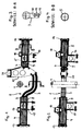
- Fig. 1
- ein Ausführungsbeispiel des erfindungsgemäßen Achskörpers samt Anbauten in Ansicht von hinten,
- Fig. 2
- den Achskörper von Fig. 1 in Draufsicht,
- Fig. 3
- den Schnitt A-A durch den Achskörper von Fig. 1
- Fig. 4
- den Schnitt B-B durch den Achskörper von Fig. 1, und
- Fig. 5
- die Teile des Achskörpers von Fig. 1 und die an diesen anzubauenden Teile in Einzeldarstellung vor ihrem Zusammenbau.
- Fig. 1
- An embodiment of the invention Achskörpers including attachments in rear view,
- Fig. 2
- the axle body of Fig. 1 in plan view,
- Fig. 3
- the section AA through the axle body of Fig. 1st
- Fig. 4
- the section BB through the axle body of Fig. 1, and
- Fig. 5
- the parts of the axle body of Fig. 1 and the parts to be mounted on these parts in an individual representation before their assembly.
Dem dargestellten Ausführungsbeispiel liegt eine Starrachse eines Fahrzeugs, hier einer
liftbaren Vor- oder Nachlaufachse eines Lastkraftwagens oder Omnibusses zugrunde, die zu
einer angetriebenen Achse benachbart und von einer Antriebsquelle 1 überquert ist, die zu
der angetriebenen Achse hinführt. Die Starrachse weist einen Achskörper 2 auf, der in seinem
Mittelbereich nach unten ausgebuchtet ist, um dort von der Antriebswelle 1 mit Abstand
oben überquert und auch - ohne diese zu berühren - angehoben bzw. geliftet werden zu
können.The illustrated embodiment is a solid axle of a vehicle, here one
Liftable leading or trailing axle of a truck or bus, the zu
adjacent to a driven axle and traversed by a drive source 1, which
the driven axis leads. The rigid axle has an
Erfindungsgemäß ist der Achskörper 2 der Starrachse gebaut und aus drei vorgefertigten
Teilen zusammengesetzt, und zwar einem geschmiedeten oder gegossenen, nach Art eines
Joches gestalteten Mittelteil 3 sowie zwei durch Rohrstücke gebildeten Seitenteilen 4, 5, die
am Mittelteil 3 angeschweißt sind. Das Mittelteil 3 ist einstückig aus hochfestem Stahlmaterial
hergestellt. Es weist an seinen beiden Enden massive plattenförmige Flansche 6, 7 auf,
deren Umfangsform und -größe jener der anzuschweißenden Seitenteile 4, 5 entspricht und
deren Anschlussflächen vertikal parallel zueinander angeordnet sind. Zwischen seinen beiden
Flanschen 6, 7 hat das Mittelteil 3 entweder einen Doppel-T-Querschnitt mit oben und
unten gegebenen Querstegen 10, 11 und einem Vertikalsteg 12 dazwischen - siehe Fig. 3 -
oder einen nach unten offenen Rechteck-Querschnitt, aber auch ein geschlossener Rechteck-Querschnitt
ist bei Guss-Ausführung möglich. According to the
Die beiden durch Rohrstücke aus, z. B. hochfestem, Stahlmaterial gebildeten Seitenteile 4, 5
des Achskörpers 2 weisen ebenso wie die Flansche 6, 7 außen am Mittelteil 3 vorzugsweise
einen kreisrunden Querschnitt auf, siehe Fig. 4.The two by pipe pieces, z. B. high-strength, steel material formed
An jedem der beiden Seitenteile 4, 5 des Achskörpers 2 ist im Fall der dargestellten Beispiels
- endseitig außen ein
Anschlussflansch - an einer Stelle des Umfangs ein
Haltebock - an anderer Stelle des Umfangs ein
Abstützplateau
- on the outside, a
connection flange - welded at one point of the circumference of a
holding bracket - at another point of the circumference a Abstützplateau 17, 18 is welded, on which an air spring is mounted supported.
Am Mittelteil 3 des Achskörpers 2 sind im Fall des dargestellten Beispiels Anlageflächen 19
für das durch Anschweißen oder Anschrauben (wie dargestellt) erfolgende Anschließen einer
nach oben abragenden Konsole 20 vorgesehen. Diese Konsole bildet die Basis oder ein
Mittel für das Anlenken eines oberen Dreiecklenkers und eines Halters, an dem ein zum Heben
und Senken (Liften) der Starrachse dienender Liftbalg oben abgestützt ist. Unten ist dieser
Liftbalg an einem rahmenfesten Halter abgestützt. Der Liftbalg wirkt vertikal zwischen
den Einspannstellen des rahmenfesten und achskörperfesten Halters. Der Dreieckslenker ist
dabei zwischen zwei obenendig an der Konsole 20 gegebenen Lagerwangen 21 z. B. über
ein Pratzengelenk an der Konsole 20 anschließbar. Der achskörperseitige Halter ist seitlich
außen an der Konsole 20 befestigbar und hat die Form eines Galgens.At the
Aufgrund dieser erfindungsgemäßen Bauart des Achskörpers ergeben sich für diesen gegenüber
einem gebogenen Achskörper der aus der GB 2258850 B bekannten Bauart folgende
Vorteile:
- Höhere Fertigungs-Prozesssicherheit für den
Achskörper 2 mit Rohr-Ø > ca. 130 mm, - kein Festigkeitsverlust hinsichtlich Ovalität in Rohrbögen (besonders bei Rohr-Ø > ca. 130 mm),
- mehr Bodenfreiheit und verringertes Achskörpergewicht durch entsprechende Gestaltung
des Querschnitts im Achskörper-
Mittelteil 3, - höhere Anzahl von Gleichteilen (die Halterungen für die Anlenkung der Achse können z. B. von einer nicht gekröpften Achse mit gleichem Rohr- Ø verwendet werden),
- im Bereich des Achskörper-
Mittelteils 3 besteht Befestigungsmöglichkeit für Halter/Konsole mittels Schraubverbindung.
- Entfall von aufwändigen Anpassungsarbeiten der Anschweißteile (höhere Prozesssicherheit in der Fertigung) → geringere Herstellkosten
- höhere Festigkeit durch:
- o Umstieg von Rohr-Ø 121x12.5 auf Rohr-Ø 150x10
- o Wegfall von festigkeitsmindernden Rohrbögen
- o Wegfall von versagenskritischen Schweißnähten innerhalb von Rohrbögen (Lagerbock- und Dreieckslenkerkonsolen-Schweißnähte)
- bessere rechnerische Beurteilung der Festigkeit durch Entfall der Schweißnaht an der Dreieckslenkerkonsole
- leichte Austauschbarkeit der Dreieckslenkerkonsole im Reparaturfall und Baukasten-Bauweise
- die Bodenfreiheit erhöht sich um ca. 10 mm
- viele Gleichteile mit einer geraden Nachlaufachse mit gleichem Achsrohr- Ø = 150x10.
- Higher manufacturing process reliability for the
axle body 2 with pipe diameter> approx. 130 mm, - no loss of strength with regard to ovality in pipe bends (especially with pipe Ø> approx. 130 mm),
- more ground clearance and reduced axle body weight by appropriate design of the cross section in the axle body
middle part 3, - higher number of identical parts (the brackets for the articulation of the axle can be used for example by a non-cranked axle with the same pipe Ø),
- in the region of the axle body
middle part 3 there is a possibility of attachment for holder / console by means of a screw connection.
- Elimination of time-consuming adaptation work of the weld-on parts (higher process reliability in production) → lower production costs
- higher strength due to:
- o Switch from pipe Ø 121x12.5 to pipe Ø 150x10
- o Elimination of strength-reducing pipe bends
- o Elimination of failure-critical welds within pipe bends (bearing block and wishbone welds)
- better computational assessment of the strength by elimination of the weld on the wishbone console
- easy interchangeability of the wishbone console in case of repair and modular design
- the ground clearance increases by approx. 10 mm
- many identical parts with a straight trailing axle with the same axle tube Ø = 150x10.
- 11
- Antriebswelledrive shaft
- 22
- Achskörperaxle body
- 33
- Mittelteil von 2Middle part of 2
- 44
- Seitenteil links von 2Side panel left of 2
- 55
- Seitenteil rechts von 2Side part right of 2
- 66
- Flansch links an 3Flange left to 3
- 77
- Flansch rechts an 3Right flange at 3
- 88th
- Anschlussfläche an 6Connection surface to 6
- 99
- Anschlussfläche an 7Connection area at 7
- 1010
- Quersteg oben an 3Crossbar at the top of 3
- 1111
- Quersteg unten an 3Crossbar below at 3
- 1212
- Vertikalsteg an 3Vertical bridge on 3
- 1313
- Anschlussflansch an 4Connection flange to 4
- 1414
- Anschlussflansch an 5Connection flange at 5
- 1515
- Haltebock an 4Bracket at 4
- 1616
- Haltebock an 5Bracket at 5
- 1717
- Abstützplateau an 4Support plateau at 4
- 1818
- Abstützplateau an 5Support plateau at 5
- 1919
- Anlageflächen an 3 für 20Investment areas at 3 for 20
- 2020
- Konsole an 3Console to 3
- 2121
- Lagerwangen oben an 20Bearing cheeks at the top of 20
Claims (6)
Applications Claiming Priority (2)
| Application Number | Priority Date | Filing Date | Title |
|---|---|---|---|
| DE10333760 | 2003-07-24 | ||
| DE2003133760 DE10333760A1 (en) | 2003-07-24 | 2003-07-24 | Rigid axle of a vehicle, in particular liftable leading or trailing axle of a truck or buses |
Publications (3)
| Publication Number | Publication Date |
|---|---|
| EP1500525A2 true EP1500525A2 (en) | 2005-01-26 |
| EP1500525A3 EP1500525A3 (en) | 2007-09-19 |
| EP1500525B1 EP1500525B1 (en) | 2009-08-26 |
Family
ID=33483048
Family Applications (1)
| Application Number | Title | Priority Date | Filing Date |
|---|---|---|---|
| EP20040015015 Expired - Lifetime EP1500525B1 (en) | 2003-07-24 | 2004-06-25 | Rigid axle for a vehicle, in particular a leading or trailing retractable axle for trucks or busses |
Country Status (2)
| Country | Link |
|---|---|
| EP (1) | EP1500525B1 (en) |
| DE (2) | DE10333760A1 (en) |
Cited By (3)
| Publication number | Priority date | Publication date | Assignee | Title |
|---|---|---|---|---|
| CN102700364A (en) * | 2011-03-16 | 2012-10-03 | 曼卡车和巴士股份公司 | Fixed axle assembly in a vehicle, in particular in a vehicle, in particular a commercial vehicle |
| EP3168060A3 (en) * | 2015-11-11 | 2017-06-21 | Dana Heavy Vehicle Systems Group, LLC | Lightweight pusher/tag axle |
| US10239371B2 (en) | 2015-11-11 | 2019-03-26 | Dana Heavy Vehicle Systems Group, Llc | Lightweight pusher/tag axle |
Families Citing this family (2)
| Publication number | Priority date | Publication date | Assignee | Title |
|---|---|---|---|---|
| BR102016024276A2 (en) | 2016-10-18 | 2018-05-02 | Kll Equipamentos Para Transporte Ltda. | DROP SUPPORT AND AXLE ASSEMBLY DEVICE |
| US12208645B2 (en) | 2022-03-31 | 2025-01-28 | Caterpillar Inc. | Front axle for mining machines |
Citations (2)
| Publication number | Priority date | Publication date | Assignee | Title |
|---|---|---|---|---|
| GB2258850B (en) | 1990-05-18 | 1993-06-30 | Phoenix Truck & Trailer Equipm | Axle beam |
| DE19920670A1 (en) | 1999-05-05 | 2000-11-23 | Man Nutzfahrzeuge Ag | Axle body for leading, trailing or lifting axles for commercial motor vehicles, has body centre sections of leading and trailing axles and of lifting axles connected to axle stubs for steered axles and non-steered axles |
Family Cites Families (2)
| Publication number | Priority date | Publication date | Assignee | Title |
|---|---|---|---|---|
| US6158750A (en) * | 1998-05-29 | 2000-12-12 | Fluidrive, Inc. | Lift axle assembly |
| US6398236B1 (en) * | 1999-07-16 | 2002-06-04 | Holland Neway International, Inc. | Lift axle suspension with axle reservoir |
-
2003
- 2003-07-24 DE DE2003133760 patent/DE10333760A1/en not_active Withdrawn
-
2004
- 2004-06-25 DE DE200450009950 patent/DE502004009950D1/en not_active Expired - Lifetime
- 2004-06-25 EP EP20040015015 patent/EP1500525B1/en not_active Expired - Lifetime
Patent Citations (2)
| Publication number | Priority date | Publication date | Assignee | Title |
|---|---|---|---|---|
| GB2258850B (en) | 1990-05-18 | 1993-06-30 | Phoenix Truck & Trailer Equipm | Axle beam |
| DE19920670A1 (en) | 1999-05-05 | 2000-11-23 | Man Nutzfahrzeuge Ag | Axle body for leading, trailing or lifting axles for commercial motor vehicles, has body centre sections of leading and trailing axles and of lifting axles connected to axle stubs for steered axles and non-steered axles |
Cited By (5)
| Publication number | Priority date | Publication date | Assignee | Title |
|---|---|---|---|---|
| CN102700364A (en) * | 2011-03-16 | 2012-10-03 | 曼卡车和巴士股份公司 | Fixed axle assembly in a vehicle, in particular in a vehicle, in particular a commercial vehicle |
| CN102700364B (en) * | 2011-03-16 | 2016-03-30 | 曼卡车和巴士股份公司 | Rigid bridge assembly in vehicle and analog bracket |
| EA025963B1 (en) * | 2011-03-16 | 2017-02-28 | Ман Трак Унд Бас Аг | Fixed axle assembly in a vehicle, in particular in a commercial vehicle |
| EP3168060A3 (en) * | 2015-11-11 | 2017-06-21 | Dana Heavy Vehicle Systems Group, LLC | Lightweight pusher/tag axle |
| US10239371B2 (en) | 2015-11-11 | 2019-03-26 | Dana Heavy Vehicle Systems Group, Llc | Lightweight pusher/tag axle |
Also Published As
| Publication number | Publication date |
|---|---|
| DE10333760A1 (en) | 2005-02-17 |
| DE502004009950D1 (en) | 2009-10-08 |
| EP1500525A3 (en) | 2007-09-19 |
| EP1500525B1 (en) | 2009-08-26 |
Similar Documents
| Publication | Publication Date | Title |
|---|---|---|
| DE19909945C1 (en) | Subframe for a motor vehicle | |
| EP1293364A2 (en) | Lateral arm for a wheel suspension | |
| DE102008061190A1 (en) | Axle suspension for a vehicle axle | |
| EP2284065A1 (en) | Front axle carrier, in particular for a motor vehicle | |
| DE2260045C3 (en) | Suspension for a sprung rigid additional wheel axle for motor vehicles | |
| DE10110495B4 (en) | Axle binding for spring-loaded vehicle axles | |
| DE19624242A1 (en) | Vehicle front wheel suspension with rigid axle | |
| DE102020129504A1 (en) | Chassis construction for a utility vehicle | |
| DE69306902T2 (en) | Suspension arm for a motor vehicle | |
| DE19809281A1 (en) | Chassis of a heavy commercial vehicle | |
| EP1500525B1 (en) | Rigid axle for a vehicle, in particular a leading or trailing retractable axle for trucks or busses | |
| EP1318036A2 (en) | Process for manufacturing a cross-beam | |
| EP0940319B1 (en) | Chassis of a heavy utility vehicle | |
| DE102006041664A1 (en) | Carrier arrangement for attachment of rear axle arrangement of lorry to vehicle frame, has cross member carrier part extending in distance to axial arrangement approximately to height of frame longitudinal carriers of vehicle frame | |
| EP3472029A1 (en) | Chassis assembly and land vehicle | |
| DE3526272A1 (en) | Axle bracket for commercial vehicles | |
| DE19631975B4 (en) | Motor vehicle axle | |
| DE102005055586A1 (en) | Four-point link for connecting a rigid axle to the frame of a vehicle, in particular a commercial vehicle | |
| DE102006047511A1 (en) | Axle system for vehicle, has axle carrier which is so connected with steering gear housing whereby axle carrier and steering gear housing together take all guided forces and internal forces | |
| EP0940322B1 (en) | Chassis for a heavy-duty utility vehicle | |
| DE102014223832A1 (en) | axle | |
| DE10122998A1 (en) | Twist beam axle and method for producing a cross member | |
| EP0940324A1 (en) | Chassis for a heavy-duty utility vehicle | |
| DE102015004858A1 (en) | Handlebar for rigid axles of commercial vehicles | |
| EP0940325A1 (en) | Chassis for a heavy-duty utility vehicle |
Legal Events
| Date | Code | Title | Description |
|---|---|---|---|
| PUAI | Public reference made under article 153(3) epc to a published international application that has entered the european phase |
Free format text: ORIGINAL CODE: 0009012 |
|
| AK | Designated contracting states |
Kind code of ref document: A2 Designated state(s): AT BE BG CH CY CZ DE DK EE ES FI FR GB GR HU IE IT LI LU MC NL PL PT RO SE SI SK TR |
|
| AX | Request for extension of the european patent |
Extension state: AL HR LT LV MK |
|
| PUAL | Search report despatched |
Free format text: ORIGINAL CODE: 0009013 |
|
| AK | Designated contracting states |
Kind code of ref document: A3 Designated state(s): AT BE BG CH CY CZ DE DK EE ES FI FR GB GR HU IE IT LI LU MC NL PL PT RO SE SI SK TR |
|
| AX | Request for extension of the european patent |
Extension state: AL HR LT LV MK |
|
| 17P | Request for examination filed |
Effective date: 20070830 |
|
| AKX | Designation fees paid |
Designated state(s): DE FR GB IT NL SE |
|
| 17Q | First examination report despatched |
Effective date: 20081104 |
|
| GRAP | Despatch of communication of intention to grant a patent |
Free format text: ORIGINAL CODE: EPIDOSNIGR1 |
|
| GRAS | Grant fee paid |
Free format text: ORIGINAL CODE: EPIDOSNIGR3 |
|
| GRAA | (expected) grant |
Free format text: ORIGINAL CODE: 0009210 |
|
| AK | Designated contracting states |
Kind code of ref document: B1 Designated state(s): DE FR GB IT NL SE |
|
| REG | Reference to a national code |
Ref country code: GB Ref legal event code: FG4D Free format text: NOT ENGLISH |
|
| REF | Corresponds to: |
Ref document number: 502004009950 Country of ref document: DE Date of ref document: 20091008 Kind code of ref document: P |
|
| REG | Reference to a national code |
Ref country code: SE Ref legal event code: TRGR |
|
| PLBE | No opposition filed within time limit |
Free format text: ORIGINAL CODE: 0009261 |
|
| STAA | Information on the status of an ep patent application or granted ep patent |
Free format text: STATUS: NO OPPOSITION FILED WITHIN TIME LIMIT |
|
| 26N | No opposition filed |
Effective date: 20100527 |
|
| REG | Reference to a national code |
Ref country code: NL Ref legal event code: TD Effective date: 20110420 |
|
| REG | Reference to a national code |
Ref country code: FR Ref legal event code: CD |
|
| REG | Reference to a national code |
Ref country code: DE Ref legal event code: R081 Ref document number: 502004009950 Country of ref document: DE Owner name: MAN TRUCK BUS AG, DE Free format text: FORMER OWNER: MAN NUTZFAHRZEUGE AG, 80995 MUENCHEN, DE Effective date: 20110518 Ref country code: DE Ref legal event code: R081 Ref document number: 502004009950 Country of ref document: DE Owner name: MAN TRUCK & BUS AG, DE Free format text: FORMER OWNER: MAN NUTZFAHRZEUGE AG, 80995 MUENCHEN, DE Effective date: 20110518 |
|
| REG | Reference to a national code |
Ref country code: FR Ref legal event code: PLFP Year of fee payment: 13 |
|
| REG | Reference to a national code |
Ref country code: FR Ref legal event code: PLFP Year of fee payment: 14 |
|
| REG | Reference to a national code |
Ref country code: FR Ref legal event code: PLFP Year of fee payment: 15 |
|
| REG | Reference to a national code |
Ref country code: DE Ref legal event code: R081 Ref document number: 502004009950 Country of ref document: DE Owner name: MAN TRUCK & BUS SE, DE Free format text: FORMER OWNER: MAN TRUCK & BUS AG, 80995 MUENCHEN, DE |
|
| PGFP | Annual fee paid to national office [announced via postgrant information from national office to epo] |
Ref country code: SE Payment date: 20230317 Year of fee payment: 20 |
|
| PGFP | Annual fee paid to national office [announced via postgrant information from national office to epo] |
Ref country code: NL Payment date: 20230626 Year of fee payment: 20 Ref country code: FR Payment date: 20230622 Year of fee payment: 20 Ref country code: DE Payment date: 20230627 Year of fee payment: 20 |
|
| PGFP | Annual fee paid to national office [announced via postgrant information from national office to epo] |
Ref country code: IT Payment date: 20230620 Year of fee payment: 20 Ref country code: GB Payment date: 20230620 Year of fee payment: 20 |
|
| REG | Reference to a national code |
Ref country code: DE Ref legal event code: R071 Ref document number: 502004009950 Country of ref document: DE |
|
| REG | Reference to a national code |
Ref country code: NL Ref legal event code: MK Effective date: 20240624 |
|
| PG25 | Lapsed in a contracting state [announced via postgrant information from national office to epo] |
Ref country code: GB Free format text: LAPSE BECAUSE OF EXPIRATION OF PROTECTION Effective date: 20240624 |
|
| REG | Reference to a national code |
Ref country code: GB Ref legal event code: PE20 Expiry date: 20240624 |
|
| REG | Reference to a national code |
Ref country code: SE Ref legal event code: EUG |
|
| PG25 | Lapsed in a contracting state [announced via postgrant information from national office to epo] |
Ref country code: GB Free format text: LAPSE BECAUSE OF EXPIRATION OF PROTECTION Effective date: 20240624 |