EP1500426A1 - Flüssigkeitsverdünnungsvorrichtung - Google Patents
Flüssigkeitsverdünnungsvorrichtung Download PDFInfo
- Publication number
- EP1500426A1 EP1500426A1 EP03708643A EP03708643A EP1500426A1 EP 1500426 A1 EP1500426 A1 EP 1500426A1 EP 03708643 A EP03708643 A EP 03708643A EP 03708643 A EP03708643 A EP 03708643A EP 1500426 A1 EP1500426 A1 EP 1500426A1
- Authority
- EP
- European Patent Office
- Prior art keywords
- passage
- connect
- jet
- negative pressure
- diluent
- Prior art date
- Legal status (The legal status is an assumption and is not a legal conclusion. Google has not performed a legal analysis and makes no representation as to the accuracy of the status listed.)
- Withdrawn
Links
Images




Classifications
-
- B—PERFORMING OPERATIONS; TRANSPORTING
- B01—PHYSICAL OR CHEMICAL PROCESSES OR APPARATUS IN GENERAL
- B01F—MIXING, e.g. DISSOLVING, EMULSIFYING OR DISPERSING
- B01F25/00—Flow mixers; Mixers for falling materials, e.g. solid particles
- B01F25/30—Injector mixers
- B01F25/31—Injector mixers in conduits or tubes through which the main component flows
- B01F25/312—Injector mixers in conduits or tubes through which the main component flows with Venturi elements; Details thereof
-
- B—PERFORMING OPERATIONS; TRANSPORTING
- B01—PHYSICAL OR CHEMICAL PROCESSES OR APPARATUS IN GENERAL
- B01F—MIXING, e.g. DISSOLVING, EMULSIFYING OR DISPERSING
- B01F23/00—Mixing according to the phases to be mixed, e.g. dispersing or emulsifying
- B01F23/40—Mixing liquids with liquids; Emulsifying
- B01F23/48—Mixing liquids with liquids; Emulsifying characterised by the nature of the liquids
- B01F23/483—Mixing liquids with liquids; Emulsifying characterised by the nature of the liquids using water for diluting a liquid ingredient, obtaining a predetermined concentration or making an aqueous solution of a concentrate
-
- B—PERFORMING OPERATIONS; TRANSPORTING
- B01—PHYSICAL OR CHEMICAL PROCESSES OR APPARATUS IN GENERAL
- B01F—MIXING, e.g. DISSOLVING, EMULSIFYING OR DISPERSING
- B01F23/00—Mixing according to the phases to be mixed, e.g. dispersing or emulsifying
- B01F23/40—Mixing liquids with liquids; Emulsifying
- B01F23/45—Mixing liquids with liquids; Emulsifying using flow mixing
- B01F23/451—Mixing liquids with liquids; Emulsifying using flow mixing by injecting one liquid into another
-
- B—PERFORMING OPERATIONS; TRANSPORTING
- B01—PHYSICAL OR CHEMICAL PROCESSES OR APPARATUS IN GENERAL
- B01F—MIXING, e.g. DISSOLVING, EMULSIFYING OR DISPERSING
- B01F25/00—Flow mixers; Mixers for falling materials, e.g. solid particles
- B01F25/30—Injector mixers
- B01F25/31—Injector mixers in conduits or tubes through which the main component flows
- B01F25/312—Injector mixers in conduits or tubes through which the main component flows with Venturi elements; Details thereof
- B01F25/3124—Injector mixers in conduits or tubes through which the main component flows with Venturi elements; Details thereof characterised by the place of introduction of the main flow
- B01F25/31242—Injector mixers in conduits or tubes through which the main component flows with Venturi elements; Details thereof characterised by the place of introduction of the main flow the main flow being injected in the central area of the venturi, creating an aspiration in the circumferential part of the conduit
-
- B—PERFORMING OPERATIONS; TRANSPORTING
- B01—PHYSICAL OR CHEMICAL PROCESSES OR APPARATUS IN GENERAL
- B01F—MIXING, e.g. DISSOLVING, EMULSIFYING OR DISPERSING
- B01F35/00—Accessories for mixers; Auxiliary operations or auxiliary devices; Parts or details of general application
- B01F35/71—Feed mechanisms
- B01F35/717—Feed mechanisms characterised by the means for feeding the components to the mixer
- B01F35/71805—Feed mechanisms characterised by the means for feeding the components to the mixer using valves, gates, orifices or openings
- B01F35/718051—Feed mechanisms characterised by the means for feeding the components to the mixer using valves, gates, orifices or openings being adjustable
-
- B—PERFORMING OPERATIONS; TRANSPORTING
- B01—PHYSICAL OR CHEMICAL PROCESSES OR APPARATUS IN GENERAL
- B01F—MIXING, e.g. DISSOLVING, EMULSIFYING OR DISPERSING
- B01F2101/00—Mixing characterised by the nature of the mixed materials or by the application field
- B01F2101/4505—Mixing ingredients comprising detergents, soaps, for washing, e.g. washing machines
-
- B—PERFORMING OPERATIONS; TRANSPORTING
- B01—PHYSICAL OR CHEMICAL PROCESSES OR APPARATUS IN GENERAL
- B01F—MIXING, e.g. DISSOLVING, EMULSIFYING OR DISPERSING
- B01F35/00—Accessories for mixers; Auxiliary operations or auxiliary devices; Parts or details of general application
- B01F35/10—Maintenance of mixers
- B01F35/145—Washing or cleaning mixers not provided for in other groups in this subclass; Inhibiting build-up of material on machine parts using other means
-
- Y—GENERAL TAGGING OF NEW TECHNOLOGICAL DEVELOPMENTS; GENERAL TAGGING OF CROSS-SECTIONAL TECHNOLOGIES SPANNING OVER SEVERAL SECTIONS OF THE IPC; TECHNICAL SUBJECTS COVERED BY FORMER USPC CROSS-REFERENCE ART COLLECTIONS [XRACs] AND DIGESTS
- Y10—TECHNICAL SUBJECTS COVERED BY FORMER USPC
- Y10T—TECHNICAL SUBJECTS COVERED BY FORMER US CLASSIFICATION
- Y10T137/00—Fluid handling
- Y10T137/8593—Systems
- Y10T137/87571—Multiple inlet with single outlet
- Y10T137/87587—Combining by aspiration
- Y10T137/87603—Plural motivating fluid jets
-
- Y—GENERAL TAGGING OF NEW TECHNOLOGICAL DEVELOPMENTS; GENERAL TAGGING OF CROSS-SECTIONAL TECHNOLOGIES SPANNING OVER SEVERAL SECTIONS OF THE IPC; TECHNICAL SUBJECTS COVERED BY FORMER USPC CROSS-REFERENCE ART COLLECTIONS [XRACs] AND DIGESTS
- Y10—TECHNICAL SUBJECTS COVERED BY FORMER USPC
- Y10T—TECHNICAL SUBJECTS COVERED BY FORMER US CLASSIFICATION
- Y10T137/00—Fluid handling
- Y10T137/8593—Systems
- Y10T137/87571—Multiple inlet with single outlet
- Y10T137/87587—Combining by aspiration
- Y10T137/87619—With selectively operated flow control means in inlet
- Y10T137/87627—Flow control means is located in aspirated fluid inlet
-
- Y—GENERAL TAGGING OF NEW TECHNOLOGICAL DEVELOPMENTS; GENERAL TAGGING OF CROSS-SECTIONAL TECHNOLOGIES SPANNING OVER SEVERAL SECTIONS OF THE IPC; TECHNICAL SUBJECTS COVERED BY FORMER USPC CROSS-REFERENCE ART COLLECTIONS [XRACs] AND DIGESTS
- Y10—TECHNICAL SUBJECTS COVERED BY FORMER USPC
- Y10T—TECHNICAL SUBJECTS COVERED BY FORMER US CLASSIFICATION
- Y10T137/00—Fluid handling
- Y10T137/8593—Systems
- Y10T137/87571—Multiple inlet with single outlet
- Y10T137/87652—With means to promote mixing or combining of plural fluids
- Y10T137/8766—With selectively operated flow control means
Definitions
- the present invention relates to a liquid dilution device to dilute a special liquid. More particularly, it relates to a liquid dilution device in which a jet for adjusting a dilution factor can be cleaned.
- the conventional liquid dilution device includes inside a body, a diluent passage for allowing passage of water (tap water), a negative pressure generate section formed in order to generate negative pressure somewhere along the diluent passage, and a liquid introduce passage connected at one end to the negative generate section and connected at the other end to a special liquid tank.
- a liquid such as water or the like
- negative pressure is generated at the negative pressure generate section.
- the special liquid is introduced from a special liquid tank into the diluent passage, and the special liquid is mixed with the water flowing in the diluent passage and thus is diluted.
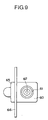
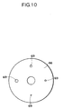
- a liquid dilution device of the related art provided with a dilution factor switching means is shown in Fig. 8 and Fig. 9, and the dilution factor switching means is shown in Fig. 10.
- One diluent passage 61 is formed inside the body 60, for introducing a diluent such as water.
- the diluent passage 61 includes a venturi section 62 formed at some midstream as a negative pressure generate section, and a diffusion section 63 formed at a downstream side of this venturi section 62 as a negative pressure generate section having a diameter larger than that of the venturi section 62.
- a connect passage 64 which connects the diffusion section 63 to the outer side of the body 60 is formed.
- a disk 66 as the dilution factor switching means, which is sandwiched by the body 60 and a holding member 65, is provided on the outer side of the body 60 at the side of an opening section of the connect passage 64.
- the disk 66 is rotatably attached to the body 60 and the holding member 65 through a bearing 68, centering around a shaft (bolt) 67 which is a fixing means for fixing the holding member 65 to the body 60.
- a plurality of jets 69 are formed at the disk 66 on the same radius from a rotation center position.
- a liquid introduce device 70 is provided on the opposite side of the body 60 to sandwich the disk 66. Then, the liquid introduce device 70 is fixed to the body 60.
- the liquid introduce device 70 includes a first body 71 and a second body 72.
- Aliquid supply passage 73 connecting to a special liquid tank, not shown in the figure, is formed inside the first body 71 and the second body 72.
- the liquid supply passage 73 is connected to the diluent passage 61 through the jet 69 formed in the disk 66 and the connect passage 64 of the body 60.
- a ring-shaped seal member 74 is attached at a position of the body 60 facing the disk 66 and surrounding the connect passage 64.
- the ring-shaped seal member 74 is for preventing leakage of water from a joint surface of the body 60 and disk 66 passing through the diluent passage 61 and the connect passage 64.
- a ring-shaped seal member 75 is attached at a position of the first body 71 of the liquid introduce device 70 facing the disk 66 and surrounding the liquid supply passage 73.
- the ring-shaped seal member 75 is for preventing leakage of a special liquid from a joint surface of the first body 71 of the liquid introduce device 70 and the disk 66 passing through the liquid supply passage 73.
- An elastic member 76 is provided at a position of the body 60 facing the disk 66 and being far from the seal member 74.
- An elastic member 77 is provided at a position of the holding member 65 facing the disk 66 and with some distance from the seal member 75.
- the connect passage 64 of the body 60 and the liquid supply passage 73 of the liquid introduce device 70 are connected through the jet 69.
- the special liquid is introduced from the liquid supply passage 73 into the diluent passage 61 by negative pressure generated in a diffusion section 63 of the diluent passage 61.
- the dilution factor switching means 66 having the plurality of jets 69 for adjusting flow amount, when a certain time passes after the jet 69 is once used, there arises a problem that the desired dilution factor cannot be obtained because the special liquid may dry out and stick to the jet 69, or the jet 69 may be choked.
- the present invention was devised in the light of the abovementioned problem.
- the object of the present invention is to provide a liquid dilution device which can prevent a jet for adjusting flow amount of the special liquid from adjusting changes or choking.
- a liquid dilution device of the present invention comprises a main body, a diluent passage formed in the main body, a negative pressure generate section formed in some midstream of the diluent passage, a first connect passage formed in the main body and connected to the negative pressure generate section, a special liquid supply passage to supply special liquid to the diluent passage through the first connect passage, a rinse liquid supply passage formed in the main body being different from the diluent passage, a negative pressure generate section formed in some midstream of the rinse liquid supply passage, a cylindrical dial disposed to be free to pivot outside the main body, a plurality of jets disposed on a specific circumference of the dial to connect the first connect passage to the special liquid supply passage, an outer body disposed outside the dial to cover the jet, an outer connect passage formed at the facing position of the dial and the outer body to be connected with the other jet than the jet which connects the first connect passage to the special liquid supply passage, a rinse liquid introduce passage connected at one side to a position which negative pressure is smaller than
- the liquid dilution device of the present invention further comprises a slot formed at the inner wall of the dial respectively, extending from the position near each jet to a position with some distance, and a cylindrical second seal member attached at a position surrounding the second connect passage of the main body, wherein the second seal member contacts invariably to the inner wall of the dial around a position at which one of the other jets is held, and the second connect passage connects to the inner connect passage via the slot corresponding to the jet at the position surrounded by the second seal member, only when each jet is at a specific position.
- the liquid dilution device of the present invention further comprises a cylindrical first seal member attached at a position surrounding the first connect passage of the main body, wherein the first seal member contacts invariably to the inner wall of the dial around a position at which the jet which connects the first connect passage with the special liquid supply passage is held, and the connection between the first connect passage and the inner connect passage is intercepted even through the slot.
- a liquid dilution device of the present invention comprises a main body, a diluent passage formed in the main body, a negative pressure generate section formed in some midstream of the diluent passage, a first connect passage formed in the main body and connected to the negative pressure generate section, a special liquid supply passage to supply special liquid to the diluent passage through the first connect passage, a cylindrical dial disposed to be free to pivot outside the main body, a plurality of jets disposed on a specific circumference of the dial to connect the first connect passage to the special liquid supply passage, an outer body disposed outside the dial to cover the jet, an outer connect passage formed at the facing position of the dial and the outer body, to be connected with the other jet than the jet which connects the first connect passage to the special liquid supply passage, an inner connect passage formed at the facing position of the dial and the main body, to be connected with the other jet, a first introduce passage connecting a relatively small negative pressure position in the diluent passage to the outer connect passage, and a second introduce passage connecting
- Fig. 1 is a sectional view showing an embodiment of the liquid dilution device of the present invention.
- Fig. 2 is a sectional view at A-A in Fig. 1.
- Fig. 3 is a sectional view of a main part of a position where a jet introduces a special liquid.
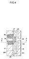
- Fig. 4 is a sectional view of a main part of a position where a jet is rinsed.
- Fig. 5 is a sectional view at B-B in Fig. 4.
- Fig. 6 is a sectional view showing another embodiment of the liquid dilution device of the present invention.
- Fig. 7 is a sectional view at C-C in Fig. 6.
- Fig. 8 is a sectional view of a liquid dilution device of the related art.
- Fig. 9 is a plain view of the liquid dilution device shown in Fig. 8.
- Fig. 10 is a front view of a dilution factor switching means used for the liquid
- Fig. 1 is a sectional view showing an embodiment of the liquid dilution device of the present invention.
- Fig. 2 is a sectional view at A-A in Fig. 1.
- a diluent main passage 11 is formed inside a main body 10 to introduce a liquid, such as water, i.e. a diluent.
- the diluent main passage 11 branches into a diluent passage 12 and a rinse liquid supply passage 13 at some midstream.
- a venturi section 14 as a negative pressure generate section is formed at some midstream of the diluent passage 12.
- a first connect passage 15 is formed in the main body 10 to connect the venturi section 14 to the outside of the main body 10.
- one diluent passage 12 and one rinse liquid supply passage 13 are formed in the main body 10.
- a cylindrical dial (a switching means) 18 having a large diameter section 16 and a small diameter section 17 is rotatably provided to the outer side of the main body 10.
- the central axis for rotation of the dial 18 is set so as to be parallel to the direction of the flow of water or the like in the diluent main passage 11, the diluent passage 12 and the rinse liquid supply passage 13.
- a plurality of jets 19a, 19b, 19c are disposed to connect the inside and the outside of the small diameter section 17.
- the plurality of jets 19a, 19b, 19c are set to be respectively varying in diameter. Three jets are disposed in Fig. 2, but it is not limited to three if the number of jets is two or more.
- a cylindrical outer body 20 is fixed to the main body 10 by a fixing means (not shown in figures).
- the cylindrical outer body 20 covers the outside of the small diameter section 17 of the dial 18.
- An oil seal 21 is provided between an upper inner wall of the cylindrical outer body 20 and an upper outer wall of the small diameter section 17 of the dial 18.
- an oil seal 22 is provided between an outer wall of the main body 10 and an inner wall of the large diameter section 16 of the dial 18.
- a liquid introduce device 26 which has a first body 23 and a second body 24 outside and has a special liquid supply passage 25 inside is fixed outside the outer body 20 by a fix means 27. Specifically, the first body 23 of the liquid introduce device 26 is fixed to the outer body 20 by the fix means 27.
- the special liquid supply passage 25 is connected to a special liquid tank (not shown in figures), and the special liquid is introduced to the special liquid supply passage 25 from the special liquid tank. In the state that the outer body 20 is fixed to the liquid introduce device 26, the special liquid supply passage 25 of the liquid introduce device 26 is connected to the first connect passage 15 of the main body 10 through a jet 19a disposed at the dial 18.
- a seal member 28 is disposed at the connecting position of the first body 23 and the dial 18.
- the seal member 28 is to prevent leakage of the special liquid to the outside when passing from the special liquid supply passage 25 of the liquid introduce device 26 to the jet 19a (the first connect passage 15 of the main body 10).
- the seal member 28 is set to contact the outer surface of the dial 18 invariably wherever the dial rotates and positions.
- a cylindrical outer connect passage 29 is formed between the inner wall of the outer body 20 and the outer wall of the cylindrical dial 18 at the facing position thereof.
- the outer connect passage 29 is connected to all the jets 19 b, 19c (called “the other jets” hereinafter) except the jet 19a which locates at a position to connect the special liquid supply passage 25 and the first connect passage 15.
- the seal member 28 prevents connection between the outer connect passage 29 and the special liquid supply passage 25 (the jet 19a) of the liquid introduce device 26. It is preferable to dispose the cylindrical outer connect passage 29 at the outer wall of the dial 18. However, it is also possible to dispose it at the inner wall of the outer body 20.
- a cylindrical inner connect passage 30 is formed at the facing position of the inner wall of the dial 18 and the outer wall of the main body 10. It is preferable to dispose the inner connect passage 30 at the outer wall of the main body 10. However, it is also possible to dispose it at the inner wall of the dial 18.
- a first seal member 31 is disposed at the outer wall of the main body 10 to prevent connection of the inner connect passage 30 with the jet 19a and the first connect passage 15.
- a ring-shaped top end project section 32 is formed at the first seal member 31. The ring-shaped top end project section 32 of the first seal member 31 is set to contact the inner wall of the dial 18 invariably. In this manner, connection of the jet 19a locating at the position to connect the special liquid supply passage 25 and the first connect passage 15 with the outer connect passage 29 is prevented by the seal member 28, and connection of that with the inner connect passage 30 is prevented by the first seal member 31.
- a venturi section 33 as the negative pressure generate section is formed at some midstream of the rinse liquid supply passage 13 which is formed in the main body 10.
- a second connect passage 34 to connect the venturi section 33 and the inner connect passage 30 is formed in the main body 10.
- the jet 19b one of the jets except the jet 19a
- the jet 19b is set to position on the extension line of the second connect passage 34. In this manner, the second connect passage 34 directly connects to the jet 19b.
- a rinse liquid introduce passage 35 connects the outer connect passage 29 with a position where the negative pressure is not larger than that of the venturi section 33 of the rinse liquid supply passage 13 (for example, a downstream position than the venturi section 33).
- the rinse liquid introduce passage 35 is formed in both the main body 10 and the outer body 20, it is not limited to this structure.
- a cylindrical second seal member 36 is attached to the outer wall of the main body 10 to prevent the connection of the inner connect passage 30 with the jet 19b or the second connect passage 34.
- a ring-shaped top end project section 37 is formed at the second seal member 36. The ring-shaped top end project section 37 is set to contact invariably to the inner wall of the dial 18 around the position to hold the jet 19b.
- a slot 38 is formed at the inner wall of the dial 18 extending from a position near the jet 19a, 19b, 19c to a position far away (for example, to the bottom end).
- the slot corresponding to the jet 19a is 38a
- the slot corresponding to the jet 19b is 38b. (The slot corresponding to the jet 19c is not shown in figures.)
- the inner connect passage 30 when the jet 19b is at the position to be connected with the second connect passage 34, the inner connect passage 30 is not to be connected with the jet 19b and the second connect passage 34 due to the contact of the second seal member 36 and the inner wall of the dial 18. However, since the upper end of the slot 38b reaches inside the ring-shaped top end project section 37 of the second seal member 36, the inner connect passage 30 connects to the second connect passage 34. As shown in Fig. 2, the jet 19c connects to the inner connect passage 30. Therefore, the jet 19c connects to the second connect passage 34 through the slot 38b.
- the ring-shaped top end project section 32 of the first seal member 31 contacts to the inner wall of the dial 18, and there is no connection of the inner connect passage 30 with the jet 19a and the first connect passage 15.
- the diameter of the ring-shaped top end project section 32 is formed to be smaller than that of the ring-shaped top end project section 37 of the second seal member 36.
- the slot 38b for the jet 19b reaches inside the ring-shaped top end project section 37 of the second seal member 36.
- the diameter of the ring-shaped top end project section 32 of the first seal member 31 is formed to be smaller than that of the ring-shaped top end project section 37 of the second seal member 36, so that the slot 38a for the jet 19a does not reach inside the ring-shaped top end project section 32 of the first seal member 31. Therefore, even when one of the other jets 19b is at the position to be connected to the first connect passage 15, the slot 38b corresponding to the jet 19b at the position does not connect with the jet 19b and the first connect passage 15.
- the dial 18 is rotated to select a jet (for example, 19a) which has a diameter that matches a desired dilution factor out of the jets 19a, 19b, 19c respectively varying in diameter.
- the selected jet 19a is lined up with the first connect passage 15 of the main body 10 and the special liquid supply passage 25 of the liquid introduce device 26.
- tap water for example, is introduced into the diluent main passage 11, the tap water is discharged outside through the diluent passage 12. In this case, negative pressure is generated at the venturi section 14 of the diluent passage 12.
- the negative pressure reaches the special liquid supply passage 25 of the liquid introduce device 26, and the special liquid is introduced to the diluent passage 12 through the jet 19a and the first connect passage 15.
- the special liquid is mixed with the tap water in the diluent passage 12, and the desired dilution factor of the special liquid can be obtained.
- it is possible to change the dilution factor of the special liquid by selecting a desired jet out of the other jets 19a, 19b, 19c respectively varying in diameter.
- the special liquid such as a chemical liquid or detergent flows through the jet 19a which connects the special liquid supply passage 25 of the liquid introduce device 26 to the first connect passage 15 of the main body 10. Therefore, the jet 19a which is used continuously has little possibility of the special liquid sticking due to drying. However, the special liquid may dry out and stick to the other jets 19b, 19c which were used before and is not used this time. Therefore, there is a possibility that the jets 19b, 19c are choked and the dilution factor deviates at the time of use thereafter.
- the tap water flows through the jets 19b, 19c to rinse simultaneously the jets 19b, 19c except the jet 19a through which the special liquid flows.
- tap water for example, is introduced into the diluent main passage 11
- the tap water flows into the rinse liquid supply passage 13 as well as the diluent passage 12.
- the tap water flows into the rinse liquid introduce passage 35 which connects to the downstream of the venturi section 33 of the rinse liquid supply passage 13.
- the rinse liquid introduce passage 35 connects to the outer connect passage 29, and the outer connect passage 29 connects to the jets 19b, 19c except the jet 19a.
- the jet 19b connects to the venturi section 33 through the second connect passage 34.
- the jet 19c connects to the venturi section 33 through the inner connect passage 30, the slot 38b corresponding to the jet 19b, and the second connect passage 34.
- the venturi section 33 of the rinse liquid supply passage 13 connects to the position, to which the rinse liquid introduce passage 35 is connected in the rinse liquid supply passage 13, through the jets 19b, 19c.
- the second seal member 36 is attached to the outer wall of the main body 10, and the second seal member 36 is arranged to contact invariably to the inner wall of the dial 18 around the position to hold the jet 19b. Then, only when the jet 19b is at the specific position (the position which is on the extension line of the second connect passage 34), the second connect passage 34 connects to the inner connect passage 30 (and the other jet 19c) through the slot 38b corresponding to the jet 19b. If the second connect passage 34, the inner connect passage 30 and all the other jets 19b, 19c are connected without disposing the second seal member 36, there is a possibility that the special liquid flows into the second connect passage 34 through the inner connect passage 30 when the dial 18 stops at some rotating midpoint. The second seal member 36 is disposed to prevent such a phenomenon.
- the diameters of the jets 19a, 19b, 19c are determined in consideration with the total water amount and the dilution factor of the special liquid.
- Fig. 6 is a sectional view showing another embodiment of the liquid dilution device of the present invention.
- Fig. 7 is a sectional view at C-C in Fig. 6.
- the same numerical shows the same member as the first embodiment.
- all the other jets 19b, 19c except the jet 19a through which the special liquid flows are continuously rinsed, and the choking at the jets 19b, 19c can be prevented.
- the second embodiment comprises the diluent passage 12 in which the venturi section 14 is formed, the outer connect passage 29, and the inner connect passage 30. Further, by the seal member 28, the connection between the passage of the special liquid from the special liquid supply passage 25 of the liquid introduce device 26 to the jet 19a (to the first connect passage 15 of the main body 10) and the outer connect passage 29 is intercepted. Furthermore, by the first seal member 31, connection of the inner connect passage 30 with the jet 19a and the first connect passage 15 is intercepted.
- the rinse liquid supply passage 13 which is formed in the first embodiment is not adopted. It is also possible not to dispose the rinse liquid supply passage 13 at the main body 10. Further, the second seal member 36 is not disposed at the main body 10.
- the first position 40 of the diluent passage 12 is the position with relatively small negative pressure (a relatively small negative pressure position).
- the second position 41 of the diluent passage 12 is the position with relatively large negative pressure (a relatively large negative pressure position).
- the first position which is the relatively small negative pressure position connects to the outer connect passage 29 through a first introduce passage 42.
- the second position 41 which is the relatively large negative pressure position connects to the inner connect passage 30 through a second introduce passage 43.
- All the other jets 19b, 19c connect to the outer connect passage 29 at one side, and connect to the inner connect passage 30 at the other side.
- the first position 40 of the diluent passage 12 connects to the second position 41 of the diluent passage 12 through the first introduce passage 42, the outer connect passage 29, the jets 19b, 19c, the inner connect passage 30, and the second introduce passage 43.
- the tap water when tap water, for example, is introduced into the diluent main passage 11, the tap water is discharged outside through the diluent passage 12. At that time, negative pressure is generated at the venturi section 14 of the diluent passage 12. The negative pressure reaches the special liquid supply passage 25 of the liquid introduce device 26. Then, the special liquid is introduced from the special liquid supply passage 25 to the diluent passage 12 through the jets 19b, 19c, and the first connect passage 15. In this manner, the special liquid is mixed with the tap water in the diluent passage 12. This is the same as the first embodiment.
- the first embodiment and the second embodiment are explained with tap water as the liquid to which the special liquid is mixed.
- tap water is not limited to tap water.
- the first position 40 of the diluent passage 12 to connect to the first introduce passage 42 and the second position 41 of the diluent passage 12 to connect to the second introduce passage 43 are located at the upstream of the venturi section 14 of the diluent passage 12.
- the first position 40 of the diluent passage 12 to connect to the first introduce passage 42 and the second position 41 of the diluent passage 12 to connect to the second introduce passage 43 are located at the downstream of the venturi section 14 of the diluent passage 12, all the other jets 19b, 19c can be rinsed.
Landscapes
- Chemical & Material Sciences (AREA)
- Chemical Kinetics & Catalysis (AREA)
- Accessories For Mixers (AREA)
- Nozzles (AREA)
Applications Claiming Priority (3)
| Application Number | Priority Date | Filing Date | Title |
|---|---|---|---|
| JP2002127108 | 2002-04-26 | ||
| JP2002127108A JP4197887B2 (ja) | 2002-04-26 | 2002-04-26 | 液体希釈装置 |
| PCT/JP2003/003168 WO2003090915A1 (en) | 2002-04-26 | 2003-03-17 | Liquid diluting device |
Publications (2)
| Publication Number | Publication Date |
|---|---|
| EP1500426A1 true EP1500426A1 (de) | 2005-01-26 |
| EP1500426A4 EP1500426A4 (de) | 2006-11-15 |
Family
ID=29267636
Family Applications (1)
| Application Number | Title | Priority Date | Filing Date |
|---|---|---|---|
| EP03708643A Withdrawn EP1500426A4 (de) | 2002-04-26 | 2003-03-17 | Flüssigkeitsverdünnungsvorrichtung |
Country Status (5)
| Country | Link |
|---|---|
| US (1) | US7108014B2 (de) |
| EP (1) | EP1500426A4 (de) |
| JP (1) | JP4197887B2 (de) |
| TW (1) | TW200400849A (de) |
| WO (1) | WO2003090915A1 (de) |
Families Citing this family (3)
| Publication number | Priority date | Publication date | Assignee | Title |
|---|---|---|---|---|
| SE525983C2 (sv) * | 2003-10-13 | 2005-06-07 | Metso Paper Inc | Blandningsanordning för inblandning av ett vätskeformigt medium i ett annat vätskeformigt medium |
| ITVI20090212A1 (it) * | 2009-08-06 | 2011-02-07 | Cristanini Spa | Miscelatore a effetto venturi ad alta efficienza |
| CN114458935B (zh) * | 2022-02-21 | 2025-11-25 | 佛山市孚泺自控技术有限公司 | 疏水装置、疏水阀及加热设备 |
Family Cites Families (14)
| Publication number | Priority date | Publication date | Assignee | Title |
|---|---|---|---|---|
| USRE25037E (en) * | 1961-09-12 | brazier | ||
| US2751974A (en) * | 1952-06-02 | 1956-06-26 | Eclipse Fuel Eng Co | Venturi type proportional mixer with means for adjusting the effective cross sectional areas of the adjacent small extremities of the outwardly flared exhaust and inwardl tapered intake passages thereof |
| US2948296A (en) * | 1958-03-24 | 1960-08-09 | Powers Regulator Co | Variable constant flow device |
| US2953160A (en) * | 1958-08-20 | 1960-09-20 | Akron Brass Mfg Co Inc | Bypass proportioner |
| US3090564A (en) * | 1961-02-21 | 1963-05-21 | Robert A Gilmour | Spraying device with dilution control |
| US3191869A (en) * | 1961-11-07 | 1965-06-29 | Gilmour Mfg Co | Spraying device having restricted orifice and expansion chamber construction |
| US3762439A (en) * | 1971-12-06 | 1973-10-02 | Parkland International Inc | Fluid mixing valve assembly |
| US4368757A (en) * | 1980-09-29 | 1983-01-18 | Sioux Steam Cleaner Corporation | Cleaning apparatus and method |
| JP3349166B2 (ja) | 1992-01-24 | 2002-11-20 | 古河電気工業株式会社 | 回路基板 |
| US5230368A (en) * | 1992-08-18 | 1993-07-27 | Shop Vac Corporation | Chemical intake system |
| JP3149166B2 (ja) | 1999-02-25 | 2001-03-26 | 株式会社ミクニ | 薬液希釈装置 |
| JP2002301347A (ja) * | 2001-01-30 | 2002-10-15 | Mikuni Corp | 液体希釈装置 |
| JP3747169B2 (ja) * | 2001-01-30 | 2006-02-22 | 株式会社ミクニ | 液体希釈装置 |
| JP2003154245A (ja) | 2001-11-26 | 2003-05-27 | Mikuni Corp | 液体希釈装置 |
-
2002
- 2002-04-26 JP JP2002127108A patent/JP4197887B2/ja not_active Expired - Fee Related
-
2003
- 2003-03-17 US US10/511,764 patent/US7108014B2/en not_active Expired - Fee Related
- 2003-03-17 WO PCT/JP2003/003168 patent/WO2003090915A1/ja not_active Ceased
- 2003-03-17 EP EP03708643A patent/EP1500426A4/de not_active Withdrawn
- 2003-03-24 TW TW92106519A patent/TW200400849A/zh unknown
Also Published As
| Publication number | Publication date |
|---|---|
| WO2003090915A1 (en) | 2003-11-06 |
| TW200400849A (en) | 2004-01-16 |
| JP2003320236A (ja) | 2003-11-11 |
| US20050217744A1 (en) | 2005-10-06 |
| EP1500426A4 (de) | 2006-11-15 |
| US7108014B2 (en) | 2006-09-19 |
| JP4197887B2 (ja) | 2008-12-17 |
Similar Documents
| Publication | Publication Date | Title |
|---|---|---|
| US5725002A (en) | Dish washing machine having interchangeable top and bottom spray arms | |
| US20100269938A1 (en) | Water-carrying domestic appliance having a water-distribution mechanism | |
| US8978674B2 (en) | Water-bearing domestic appliance with a water diverter | |
| US6547966B2 (en) | In-line basket filter for a spray spout assembly | |
| CN101379330A (zh) | 用于水处理系统的具有累积流量传感器的旁通阀 | |
| US10946395B2 (en) | Shower head | |
| US7108014B2 (en) | Liquid diluting device | |
| US6929033B2 (en) | Liquid dilution device | |
| US6789571B2 (en) | Liquid dilution device | |
| KR101230502B1 (ko) | 혼합밸브 | |
| US4344452A (en) | Water feed valve with sprinkling holes | |
| JP3642892B2 (ja) | 処理液吐出ノズルおよび基板処理装置 | |
| US20070080241A1 (en) | Aerator sleeve attachment | |
| US20080060709A1 (en) | Adjustable water-dispersing device for a faucet | |
| CN221205333U (zh) | 一种加强洗结构及洗碗机 | |
| JPH0617954A (ja) | バルブ | |
| CN218763584U (zh) | 喷嘴结构及吸油烟机 | |
| CN113578546B (zh) | 出水装置及厨房花洒 | |
| CN113827160B (zh) | 清洗机用洗涤容器及清洗机 | |
| KR100481802B1 (ko) | 티에스 밸브 | |
| KR950013462A (ko) | 식기세척기의 우유병 세척장치 | |
| JPH11153231A (ja) | 薬液供給バルブおよび薬液供給装置 | |
| CN116919288A (zh) | 用于洗碗机的喷淋器和洗碗机 | |
| CN118896170A (zh) | 多路阀、包含阀的载水家用装置以及用于操作家用装置的方法 | |
| JP2002301347A (ja) | 液体希釈装置 |
Legal Events
| Date | Code | Title | Description |
|---|---|---|---|
| PUAI | Public reference made under article 153(3) epc to a published international application that has entered the european phase |
Free format text: ORIGINAL CODE: 0009012 |
|
| 17P | Request for examination filed |
Effective date: 20041104 |
|
| AK | Designated contracting states |
Kind code of ref document: A1 Designated state(s): AT BE BG CH CY CZ DE DK EE ES FI FR GB GR HU IE IT LI LU MC NL PT RO SE SI SK TR |
|
| A4 | Supplementary search report drawn up and despatched |
Effective date: 20061017 |
|
| STAA | Information on the status of an ep patent application or granted ep patent |
Free format text: STATUS: THE APPLICATION IS DEEMED TO BE WITHDRAWN |
|
| 18D | Application deemed to be withdrawn |
Effective date: 20070116 |