EP1500363A1 - Handgriff eines Haushaltsgeräts - Google Patents
Handgriff eines Haushaltsgeräts Download PDFInfo
- Publication number
- EP1500363A1 EP1500363A1 EP04015417A EP04015417A EP1500363A1 EP 1500363 A1 EP1500363 A1 EP 1500363A1 EP 04015417 A EP04015417 A EP 04015417A EP 04015417 A EP04015417 A EP 04015417A EP 1500363 A1 EP1500363 A1 EP 1500363A1
- Authority
- EP
- European Patent Office
- Prior art keywords
- handle
- handle according
- container
- connecting portion
- bodies
- Prior art date
- Legal status (The legal status is an assumption and is not a legal conclusion. Google has not performed a legal analysis and makes no representation as to the accuracy of the status listed.)
- Granted
Links
- 239000007788 liquid Substances 0.000 claims description 5
- 229910052751 metal Inorganic materials 0.000 claims description 4
- 239000002184 metal Substances 0.000 claims description 4
- 239000011796 hollow space material Substances 0.000 abstract 1
- 230000003014 reinforcing effect Effects 0.000 abstract 1
- 238000005452 bending Methods 0.000 description 4
- 238000001746 injection moulding Methods 0.000 description 3
- 238000004519 manufacturing process Methods 0.000 description 2
- 239000007787 solid Substances 0.000 description 2
- 230000007704 transition Effects 0.000 description 2
- XLYOFNOQVPJJNP-UHFFFAOYSA-N water Substances O XLYOFNOQVPJJNP-UHFFFAOYSA-N 0.000 description 2
- 229910000838 Al alloy Inorganic materials 0.000 description 1
- 229910000861 Mg alloy Inorganic materials 0.000 description 1
- XAGFODPZIPBFFR-UHFFFAOYSA-N aluminium Chemical compound [Al] XAGFODPZIPBFFR-UHFFFAOYSA-N 0.000 description 1
- 238000005266 casting Methods 0.000 description 1
- 230000001419 dependent effect Effects 0.000 description 1
- 238000011161 development Methods 0.000 description 1
- 230000018109 developmental process Effects 0.000 description 1
- 230000000694 effects Effects 0.000 description 1
- 238000005485 electric heating Methods 0.000 description 1
- 230000008093 supporting effect Effects 0.000 description 1
Images


Classifications
-
- A—HUMAN NECESSITIES
- A47—FURNITURE; DOMESTIC ARTICLES OR APPLIANCES; COFFEE MILLS; SPICE MILLS; SUCTION CLEANERS IN GENERAL
- A47J—KITCHEN EQUIPMENT; COFFEE MILLS; SPICE MILLS; APPARATUS FOR MAKING BEVERAGES
- A47J45/00—Devices for fastening or gripping kitchen utensils or crockery
- A47J45/06—Handles for hollow-ware articles
- A47J45/08—Heat-insulating handles
-
- A—HUMAN NECESSITIES
- A47—FURNITURE; DOMESTIC ARTICLES OR APPLIANCES; COFFEE MILLS; SPICE MILLS; SUCTION CLEANERS IN GENERAL
- A47J—KITCHEN EQUIPMENT; COFFEE MILLS; SPICE MILLS; APPARATUS FOR MAKING BEVERAGES
- A47J27/00—Cooking-vessels
- A47J27/21—Water-boiling vessels, e.g. kettles
- A47J27/21008—Water-boiling vessels, e.g. kettles electrically heated
- A47J27/21058—Control devices to avoid overheating, i.e. "dry" boiling, or to detect boiling of the water
- A47J27/21066—Details concerning the mounting thereof in or on the water boiling vessel
- A47J27/21075—Details concerning the mounting thereof in or on the water boiling vessel relating to the boiling sensor or to the channels conducting the steam thereto
Definitions
- the present invention relates to a handle for a household appliance or a Handle of a household appliance, in particular for a container for liquids, with the features of the preamble of claim 1.
- Household appliances in the form of containers for liquids are in different Forms known, for example, as planteoliergefäße, as a kettle, as decanters or similar.
- a handle is usually at an upper portion of the vessel attached and runs in a vertical direction, allowing the vessel to pour out the can be handled therein liquid or held.
- the handle may optionally have another attachment point in a middle or lower region of the Identify vessel, which is not absolutely necessary. With only one The upper portion of the container-mounted handle must have this sufficient Have stiffness, even with a filled container or vessel no deformation to show.
- the upper attachment point must be sufficiently stable, so that the handle can not bend there. This concerns in particular handles Plastic.
- Such plantesisoliergefäße with a handle at both ends with the pot is screwed, for example, from DE 14 542 27 A1, DE 19 011 51 U1 and from DE 19 015 14 U1 known.
- Heat insulating vessels where the handle only in an upper area is attached to a container, so that the handle is a free have lower end, are, for example, from DE 72 122 42 U1 and DE 84 119 95th U1 known.
- These known handles are each formed in one piece and can be made either solid or partially hollow.
- the handle often consists of a handle base, which is usually integral with the container formed, for example. Is molded in a single casting.
- a handle top usually as a cover is formed and, for example, may have a semicircular cross-section.
- a simple pre-assembly is usually not possible in such an embodiment, so that the Components must be mounted individually.
- a one-piece handle of a household appliance with a C-shaped handle part, which in one reinforced gripping area and at an upper and a lower end is attached to the household appliance, is further known from DE 196 38 662 A1.
- Of the Handle is hollow and substantially closed in the gripping area.
- the handle part is through a first and a second part body formed, which are interconnected and are hinged together.
- the present invention is based on the object, a handle for a Household appliance, in particular for a container for liquids available place, which has a high dimensional stability in weight-saving design.
- An inventive handle for a household appliance has a substantially closed and hollow handle part, which is provided with stiffening struts. Especially with a fastening of the handle on the container with only one Junction occur when handling a heavy, eg. With water filled container high loads, which due to the struts not too lead to a greater deflection of the handle.
- the handle consists of two Handle halves or part bodies, each having an inner brace, so that the both handle halves in the interconnected state a stable handle for Form handling of the container.
- the two-part design is necessary because otherwise the bracing hardly or only with considerable effort in the Hollow body of the handle part could be introduced.
- the two handle halves can be made in particular of plastic or light metal injection molding exist and locked in the interconnected state stably with each other.
- Through the inner bracing and the form-fitting and non-positively with each other latchable connection of the two handle halves is formed a very stable handle structure, even with filled containers and with a version of the handle with relatively thin Wall thicknesses can not lead to deformation.
- the production of the two Part body injection molding allows only the trouble-free design of the inner Struts, since in this way hardly undercuts of the mold are necessary. Due to the positive and non-positive connection of the two handle halves of the cavity formed of the handle part, which has the desired dimensional stability during operation.
- the handle can be screwed at the junction in particular with the container and / or be locked.
- a further embodiment of the invention can provide that the handle has a longer connecting portion extending along the Container wall leads down and preferably flush with this and closes with the Container wall is connectable. This connection section can be used in particular Inserting the handle inserted into a corresponding recess on the container wall be so that the handle rests flush mounted on the container wall in the assembled state.
- the connecting portion can in two ways as the handle in the same way be executed, wherein the two parts preferably by Klips- or latching connections positively and non-positively connected to one another.
- a Transition between handle and connecting section can be a further stiffening of the handle can be achieved, so that its dimensional stability is given at all times.
- connecting portion forms a support the handle against the outer wall of the container.
- the inventive design of the handle allows its manufacture and Pre-assembly as a complete sub-assembly or as a module, possibly one more may have electrical switch together with its wiring.
- the two Handle halves are joined together by means of locking hooks made of plastic, whereby Also, the wiring of the switch positioned in the region of the connection section What can be supported, for example, with the help of suitable eyelets.
- the result formed sub-assembly "handle” is using hooks on the container wall hung and possibly locked there.
- a counterpart inside the container can then bolted to the handle, preferably at the top Junction, whereby a stable connection is made, the one Has positive connection and a positive connection between the container and handle.
- the Handle halves are also under higher load due to the interlocking geometric shapes are not mutually displaceable.
- the handle according to the invention for a household appliance is shown in Figures 1 to 4 am Example of a handle for a kettle 8 explained in more detail.
- a Kettle 8 according to Figure 1 usually has a top openable and provided with an upper spout can or carafe-like container 10 from Plastic on which at least one handle 12 is attached, which is a vertical Has longitudinal direction.
- the handle 12 is at least with an upper one End 14 attached to an upper portion 16 of the container 10.
- the handle 12 can optionally be attached to the container 10 with its lower end 18.
- the handle 12 normally off Plastic, is both the junction 20 of the upper mounting on Container 10 as well as in particular the upper curved portion 22 of a partial exposed to considerable bending load. This bending load is the handle 12 exposed in particular with a full container 10.
- the handle 12 Since the handle 12 is usually not solid, but closed and hollow is formed, it consists in the illustrated embodiment of two in vertical Direction divided part bodies 121 and 122, which positively and non-positively with each other are connectable. In interconnected part bodies 121, 122, the handle 12th a closed structure with inner cavity 123 on.
- Figure 2 illustrates in one Top view from above the vertically divisible handle 12, the upper curved portion 22 may optionally have a switch 24 with which an electric Heating device (not shown) in the lower inner region of the container 10 is activated can be.
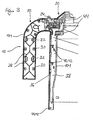
- Figure 3 illustrates a longitudinal section of the handle 12 along the section line III-III of FIG. 2. Shown here is a plan view of the first partial body 121, from which in FIG this view, the second body part 122 is removed.
- the inner one Cavity 123 preferably stiffened by means of braces 26.
- These struts 26 may for example be formed like a grid, as illustrated in Figure 3 is.
- the struts 26 preferably extend over the entire length of the Handle 12 and the two part body 121 and 122nd
- each receptacle 32 is each designed so that the corresponding latching hook 30 engage in a form-fitting manner and then it can engage there.
- the pictures 32 and latching hooks 30 are respectively at the adjacent longitudinal edges of Part body 121, 122 arranged, with a latching hook 30 each in a small Distance a shot 32 follows.
- the thus connectable second partial body 122 thus has the same number of receptacles 32 and latching hooks 30, so that a dimensionally stable connection between the two partial bodies 121 and 122 is made possible.
- the handle 12 may have a connecting portion 36 which at mounted handle 12 is flush with the container wall 101.
- the Connecting portion 36 may also have a vertical course, so that he forms a support against the container wall 101.
- the Connecting portion 36 equally divided in the vertical direction as well as the Handle 12 itself, so that both part bodies 121, 122 each consist of a handle half and a connecting portion half.
- connection between handle 12 and container 10 is good with reference to FIG recognizable.
- the fastening means are each as Locking receptacles 40 formed in the corresponding hook 42 of the Connecting portion 36 can engage detent.
- the upper End 14 of the handle 12 additionally by means of at least one screw 44 on Container 10 to be attached.
- This screw 44 is preferably of the Container inside set and fixed, so that the handle 12 in optically advantageous Way can be connected to the container 10, without any from the outside Connecting or screwing points are visible.
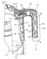
- Figure 4 illustrates in a perspective partial section the connection between the two part bodies 121, 122 of the handle 12 and its fixation on the container 10th In the area of the receiving trough 38, the container wall 101 is curved inwards, so that the connecting portion 36 of the handle 12 is largely flush with the outer Can close container wall 101.
- Recognizable are also the over the entire cavity 123 of the handle 12th extending struts 26 in the form of interconnected and intertwined transitional framework or grid-like webs.
- the stability of the particularly highly loaded on bending joint 20 is on the one hand by the downwardly supporting effect of the connecting portion 36 and further ensured by the stable screw 44.
- the braces 26 extend for reasons of better bending stiffness preferably into the Area of the switch 24, wherein for this possibly corresponding recesses in the Struts are to be provided.
- Container 10 and handle 12 may be made of plastic, for example. By means of Injection molding can be processed. However, the handle 12 may also be off Metal, for example. Of light metal such as an aluminum and / or magnesium alloy exist, which can achieve particularly advantageous design effects.
- the handle according to the invention is particularly suitable for use within a device series with largely the same stylistic devices. Possibly. can he Handle even be used for different devices of such a series.
Landscapes
- Engineering & Computer Science (AREA)
- Food Science & Technology (AREA)
- Details Of Rigid Or Semi-Rigid Containers (AREA)
- Cookers (AREA)
Abstract
Description
- 8
- Wasserkocher
- 10
- Behälter
- 101
- Behälterwand
- 12
- Handgriff
- 121
- erster Teilkörper
- 122
- zweiter Teilkörper
- 123
- Hohlraum
- 14
- oberes Ende
- 16
- oberer Bereich
- 18
- freies Ende
- 20
- Verbindungsstelle
- 22
- gekrümmter Abschnitt
- 24
- Schalter
- 26
- Verstrebung
- 30
- Rasthaken
- 32
- Aufnahme
- 36
- Verbindungsabschnitt
- 38
- Aufnahmemulde
- 40
- Rastaufnahme
- 42
- Haken
- 44
- Verschraubung
Claims (12)
- Handgriff eines Haushaltsgeräts bzw. für ein Haushaltsgerät, insbesondere für einen Behälter (10) für Flüssigkeiten, der eine vertikale Längserstreckungsrichtung und ein im Wesentliches hohles, geschlossenes und in vertikaler Richtung geteiltes Griffteil aufweist, das einen ersten Teilkörper (121) und einen zweiten Teilkörper (122) umfasst, die miteinander verbindbar sind, und der zumindest mit einem oberen Ende (14) an einer äußeren Behälterwand (101) befestigt ist, dadurch gekennzeichnet, dass der innere Hohlraum (103) des Griffteils versteifende Verstrebungen (26) aufweist.
- Handgriff nach Anspruch 1, dadurch gekennzeichnet, dass die beiden Teilkörper (121, 122) fest miteinander verrastbar sind.
- Handgriff nach Anspruch 1 oder 2, dadurch gekennzeichnet, dass die beiden Teilkörper (121, 122) über wenigstens zwei Rastverbindungen miteinander verrastbar sind.
- Handgriff nach einem der voranstehenden Ansprüche, dadurch gekennzeichnet, dass jeweils ein Rasthaken (30) eines Teilkörpers (121 bzw. 122) in eine damit korrespondierende Aufnahme (32) des jeweils anderen Teilkörpers (122 bzw. 121) formschlüssig eingreift.
- Handgriff nach einem der voranstehenden Ansprüche, dadurch gekennzeichnet, dass die beiden Teilkörper (121, 122) im miteinander verrasteten Zustand formschlüssig und kraftschlüssig miteinander verbunden sind.
- Handgriff nach einem der voranstehenden Ansprüche, dadurch gekennzeichnet, dass die beiden Teilkörper (121, 122) jeweils über wenigstens eine Schraubverbindung (44) an der äußeren Behälterwand (101) fixierbar sind.
- Handgriff nach einem der voranstehenden Ansprüche, dadurch gekennzeichnet, dass der Handgriff (12) mit seinem oberen Ende (14) an der äußeren Behälterwand (101) fixierbar ist und ein unteres freies Ende (18) aufweist.
- Handgriff nach einem der voranstehenden Ansprüche, dadurch gekennzeichnet, dass die beiden Teilkörper (121, 122) jeweils einen Verbindungsabschnitt (36) aufweisen, und dass diese im montierten Zustand des Handgriffs (12) formschlüssig ineinander greifen.
- Handgriff nach Anspruch 8, dadurch gekennzeichnet, dass der längliche Verbindungsabschnitt (36) bündig mit der Außenwand (101) des Behälters (10) verbindbar ist.
- Handgriff nach Anspruch 8 oder 9, dadurch gekennzeichnet, dass der Verbindungsabschnitt (36) eine vertikale Längserstreckungsrichtung aufweist.
- Handgriff nach einem der Ansprüche 8 bis 10, dadurch gekennzeichnet, dass der Verbindungsabschnitt (36) eine Abstützung des Handgriffs (12) gegen die Behälterwand (101) bildet.
- Handgriff nach einem der voranstehenden Ansprüche, dadurch gekennzeichnet, dass der Handgriff (12) aus Kunststoff oder aus Leichtmetall besteht.
Applications Claiming Priority (2)
| Application Number | Priority Date | Filing Date | Title |
|---|---|---|---|
| DE2003133125 DE10333125A1 (de) | 2003-07-21 | 2003-07-21 | Handgriff eines Haushaltsgeräts |
| DE10333125 | 2003-07-21 |
Publications (2)
| Publication Number | Publication Date |
|---|---|
| EP1500363A1 true EP1500363A1 (de) | 2005-01-26 |
| EP1500363B1 EP1500363B1 (de) | 2007-06-27 |
Family
ID=33482994
Family Applications (1)
| Application Number | Title | Priority Date | Filing Date |
|---|---|---|---|
| EP20040015417 Expired - Lifetime EP1500363B1 (de) | 2003-07-21 | 2004-06-30 | Handgriff eines Haushaltsgeräts |
Country Status (3)
| Country | Link |
|---|---|
| EP (1) | EP1500363B1 (de) |
| CN (1) | CN1575704A (de) |
| DE (2) | DE10333125A1 (de) |
Cited By (1)
| Publication number | Priority date | Publication date | Assignee | Title |
|---|---|---|---|---|
| US20220117434A1 (en) * | 2019-01-25 | 2022-04-21 | Lg Electronics Inc. | Electric kettle |
Citations (4)
| Publication number | Priority date | Publication date | Assignee | Title |
|---|---|---|---|---|
| US4982869A (en) * | 1989-11-07 | 1991-01-08 | Robbins Edward S Iii | Pivoting handle type pitcher for thin walled container |
| DE8915936U1 (de) * | 1989-01-31 | 1992-04-16 | ABC-Elektrogeräte Volz, GmbH & Co, 7312 Kirchheim | Glaskanne mit Handgriff |
| EP1051943A1 (de) * | 1999-05-10 | 2000-11-15 | La Termoplastic F.B.M. S.R.L. | Griff für ein Kochgerät |
| EP1177754A1 (de) * | 2000-08-03 | 2002-02-06 | La Termoplastic F.B.M. S.R.L. | Zweiteiliger Handgriff für ein Kochgerät, insbesondere für einen Deckel |
Family Cites Families (4)
| Publication number | Priority date | Publication date | Assignee | Title |
|---|---|---|---|---|
| DE2712273C2 (de) * | 1977-03-21 | 1985-11-28 | Hartolit Adalbert Schmitt, 6983 Kreuzwertheim | Griffbefestigung für Isolierkannen, Isolierflaschen, Isoliergefäße o.dgl. |
| GB2103720B (en) * | 1981-08-10 | 1985-04-11 | Bespak Industries Ltd | Handle assembly for a pressurised dispensing container |
| JPH1075902A (ja) * | 1996-09-03 | 1998-03-24 | Nippon Sanso Kk | 栓付液体容器 |
| DE19638662C2 (de) * | 1996-09-20 | 1999-03-18 | Bosch Siemens Hausgeraete | Handgriff eines Haushaltgerätes |
-
2003
- 2003-07-21 DE DE2003133125 patent/DE10333125A1/de not_active Withdrawn
-
2004
- 2004-06-30 EP EP20040015417 patent/EP1500363B1/de not_active Expired - Lifetime
- 2004-06-30 DE DE200450004176 patent/DE502004004176D1/de not_active Expired - Lifetime
- 2004-07-21 CN CN 200410071681 patent/CN1575704A/zh active Pending
Patent Citations (4)
| Publication number | Priority date | Publication date | Assignee | Title |
|---|---|---|---|---|
| DE8915936U1 (de) * | 1989-01-31 | 1992-04-16 | ABC-Elektrogeräte Volz, GmbH & Co, 7312 Kirchheim | Glaskanne mit Handgriff |
| US4982869A (en) * | 1989-11-07 | 1991-01-08 | Robbins Edward S Iii | Pivoting handle type pitcher for thin walled container |
| EP1051943A1 (de) * | 1999-05-10 | 2000-11-15 | La Termoplastic F.B.M. S.R.L. | Griff für ein Kochgerät |
| EP1177754A1 (de) * | 2000-08-03 | 2002-02-06 | La Termoplastic F.B.M. S.R.L. | Zweiteiliger Handgriff für ein Kochgerät, insbesondere für einen Deckel |
Cited By (2)
| Publication number | Priority date | Publication date | Assignee | Title |
|---|---|---|---|---|
| US20220117434A1 (en) * | 2019-01-25 | 2022-04-21 | Lg Electronics Inc. | Electric kettle |
| US12171360B2 (en) * | 2019-01-25 | 2024-12-24 | Lg Electronics Inc. | Electric kettle |
Also Published As
| Publication number | Publication date |
|---|---|
| EP1500363B1 (de) | 2007-06-27 |
| DE10333125A1 (de) | 2005-02-17 |
| CN1575704A (zh) | 2005-02-09 |
| DE502004004176D1 (de) | 2007-08-09 |
Similar Documents
| Publication | Publication Date | Title |
|---|---|---|
| DE2851987C2 (de) | Stützvorrichtung für Leitern | |
| EP1599113B1 (de) | Türgriff | |
| DE202005001914U1 (de) | Gargefäß | |
| EP2172141B1 (de) | Kochgeschirr mit abnehmbarem Griff- oder Stielelement | |
| EP1226363B1 (de) | Beschlag zur lösbaren befestigung an einem möbelteil | |
| EP0458254A2 (de) | Befestigungsvorrichtung zur Befestigung eines Griffelementes an einem Kochgeschirr | |
| EP2310775B1 (de) | Haushaltsgerät mit einer abdeckung zum abdecken eines lagerwinkels | |
| EP1500363B1 (de) | Handgriff eines Haushaltsgeräts | |
| EP1500355B1 (de) | Handgriff eines Haushaltsgerätes | |
| EP1127760B1 (de) | Betätigungsvorrichtung für eine Feststellbremse | |
| DE10065967B4 (de) | Zugentlastungsgehäuse für elektrische Bauteile | |
| DE20321388U1 (de) | Handgriff eines Haushaltsgeräts | |
| DE202020101657U1 (de) | Garderobenlift | |
| EP1925244B1 (de) | Kochgefäss | |
| DE102007031887A1 (de) | Geschirrkorb mit klappbarer Ablage | |
| WO2019145563A1 (de) | Von hand bewegbarer einkaufswagen | |
| EP1354825B1 (de) | Müllbehälter mit verstärkter Zapfen-Einheit | |
| WO2010015492A1 (de) | Griffbefestigung | |
| DE102007020817B3 (de) | Freischwingerstuhl | |
| DE102016206352A1 (de) | Griff für eine Tür eines Haushaltsgargeräts, Tür für ein Haushaltsgargerät und Haushaltsgargerät | |
| DE102005058106A1 (de) | Untergestell für eine Sanitärwanne | |
| EP1044642A1 (de) | Kochgefäss | |
| EP0442447B1 (de) | Dampfdruckkochtopf | |
| EP2348591B1 (de) | Tragarm | |
| DE3716965C2 (de) |
Legal Events
| Date | Code | Title | Description |
|---|---|---|---|
| PUAI | Public reference made under article 153(3) epc to a published international application that has entered the european phase |
Free format text: ORIGINAL CODE: 0009012 |
|
| AK | Designated contracting states |
Kind code of ref document: A1 Designated state(s): AT BE BG CH CY CZ DE DK EE ES FI FR GB GR HU IE IT LI LU MC NL PL PT RO SE SI SK TR |
|
| AX | Request for extension of the european patent |
Extension state: AL HR LT LV MK |
|
| 17P | Request for examination filed |
Effective date: 20050726 |
|
| AKX | Designation fees paid |
Designated state(s): DE FR GB |
|
| GRAP | Despatch of communication of intention to grant a patent |
Free format text: ORIGINAL CODE: EPIDOSNIGR1 |
|
| GRAS | Grant fee paid |
Free format text: ORIGINAL CODE: EPIDOSNIGR3 |
|
| GRAA | (expected) grant |
Free format text: ORIGINAL CODE: 0009210 |
|
| AK | Designated contracting states |
Kind code of ref document: B1 Designated state(s): DE FR GB |
|
| REG | Reference to a national code |
Ref country code: GB Ref legal event code: FG4D Free format text: NOT ENGLISH |
|
| GBT | Gb: translation of ep patent filed (gb section 77(6)(a)/1977) |
Effective date: 20070705 |
|
| REF | Corresponds to: |
Ref document number: 502004004176 Country of ref document: DE Date of ref document: 20070809 Kind code of ref document: P |
|
| ET | Fr: translation filed | ||
| PLBE | No opposition filed within time limit |
Free format text: ORIGINAL CODE: 0009261 |
|
| STAA | Information on the status of an ep patent application or granted ep patent |
Free format text: STATUS: NO OPPOSITION FILED WITHIN TIME LIMIT |
|
| 26N | No opposition filed |
Effective date: 20080328 |
|
| REG | Reference to a national code |
Ref country code: DE Ref legal event code: R081 Ref document number: 502004004176 Country of ref document: DE Owner name: BSH HAUSGERAETE GMBH, DE Free format text: FORMER OWNER: BSH BOSCH UND SIEMENS HAUSGERAETE GMBH, 81739 MUENCHEN, DE Effective date: 20150407 |
|
| REG | Reference to a national code |
Ref country code: FR Ref legal event code: PLFP Year of fee payment: 12 |
|
| REG | Reference to a national code |
Ref country code: FR Ref legal event code: CD Owner name: BSH HAUSGERATE GMBH Effective date: 20151022 |
|
| REG | Reference to a national code |
Ref country code: FR Ref legal event code: PLFP Year of fee payment: 13 |
|
| PGFP | Annual fee paid to national office [announced via postgrant information from national office to epo] |
Ref country code: GB Payment date: 20160628 Year of fee payment: 13 |
|
| PGFP | Annual fee paid to national office [announced via postgrant information from national office to epo] |
Ref country code: FR Payment date: 20160621 Year of fee payment: 13 |
|
| PGFP | Annual fee paid to national office [announced via postgrant information from national office to epo] |
Ref country code: DE Payment date: 20160630 Year of fee payment: 13 |
|
| REG | Reference to a national code |
Ref country code: DE Ref legal event code: R119 Ref document number: 502004004176 Country of ref document: DE |
|
| GBPC | Gb: european patent ceased through non-payment of renewal fee |
Effective date: 20170630 |
|
| REG | Reference to a national code |
Ref country code: FR Ref legal event code: ST Effective date: 20180228 |
|
| PG25 | Lapsed in a contracting state [announced via postgrant information from national office to epo] |
Ref country code: GB Free format text: LAPSE BECAUSE OF NON-PAYMENT OF DUE FEES Effective date: 20170630 Ref country code: DE Free format text: LAPSE BECAUSE OF NON-PAYMENT OF DUE FEES Effective date: 20180103 |
|
| PG25 | Lapsed in a contracting state [announced via postgrant information from national office to epo] |
Ref country code: FR Free format text: LAPSE BECAUSE OF NON-PAYMENT OF DUE FEES Effective date: 20170630 |