EP1499249B1 - Apparatus for aligning and positioning implants in a body - Google Patents
Apparatus for aligning and positioning implants in a body Download PDFInfo
- Publication number
- EP1499249B1 EP1499249B1 EP03747501A EP03747501A EP1499249B1 EP 1499249 B1 EP1499249 B1 EP 1499249B1 EP 03747501 A EP03747501 A EP 03747501A EP 03747501 A EP03747501 A EP 03747501A EP 1499249 B1 EP1499249 B1 EP 1499249B1
- Authority
- EP
- European Patent Office
- Prior art keywords
- jig
- assembly
- arm
- nail
- support device
- Prior art date
- Legal status (The legal status is an assumption and is not a legal conclusion. Google has not performed a legal analysis and makes no representation as to the accuracy of the status listed.)
- Expired - Lifetime
Links
Images


Classifications
-
- A—HUMAN NECESSITIES
- A61—MEDICAL OR VETERINARY SCIENCE; HYGIENE
- A61B—DIAGNOSIS; SURGERY; IDENTIFICATION
- A61B17/00—Surgical instruments, devices or methods, e.g. tourniquets
- A61B17/16—Bone cutting, breaking or removal means other than saws, e.g. Osteoclasts; Drills or chisels for bones; Trepans
- A61B17/17—Guides or aligning means for drills, mills, pins or wires
- A61B17/1725—Guides or aligning means for drills, mills, pins or wires for applying transverse screws or pins through intramedullary nails or pins
-
- A—HUMAN NECESSITIES
- A61—MEDICAL OR VETERINARY SCIENCE; HYGIENE
- A61B—DIAGNOSIS; SURGERY; IDENTIFICATION
- A61B17/00—Surgical instruments, devices or methods, e.g. tourniquets
- A61B17/16—Bone cutting, breaking or removal means other than saws, e.g. Osteoclasts; Drills or chisels for bones; Trepans
- A61B17/17—Guides or aligning means for drills, mills, pins or wires
- A61B17/1703—Guides or aligning means for drills, mills, pins or wires using imaging means, e.g. by X-rays
-
- A—HUMAN NECESSITIES
- A61—MEDICAL OR VETERINARY SCIENCE; HYGIENE
- A61B—DIAGNOSIS; SURGERY; IDENTIFICATION
- A61B17/00—Surgical instruments, devices or methods, e.g. tourniquets
- A61B17/16—Bone cutting, breaking or removal means other than saws, e.g. Osteoclasts; Drills or chisels for bones; Trepans
- A61B17/17—Guides or aligning means for drills, mills, pins or wires
- A61B17/1739—Guides or aligning means for drills, mills, pins or wires specially adapted for particular parts of the body
- A61B17/1764—Guides or aligning means for drills, mills, pins or wires specially adapted for particular parts of the body for the knee
-
- A—HUMAN NECESSITIES
- A61—MEDICAL OR VETERINARY SCIENCE; HYGIENE
- A61B—DIAGNOSIS; SURGERY; IDENTIFICATION
- A61B17/00—Surgical instruments, devices or methods, e.g. tourniquets
- A61B2017/00831—Material properties
- A61B2017/00902—Material properties transparent or translucent
-
- A—HUMAN NECESSITIES
- A61—MEDICAL OR VETERINARY SCIENCE; HYGIENE
- A61B—DIAGNOSIS; SURGERY; IDENTIFICATION
- A61B90/00—Instruments, implements or accessories specially adapted for surgery or diagnosis and not covered by any of the groups A61B1/00 - A61B50/00, e.g. for luxation treatment or for protecting wound edges
- A61B90/39—Markers, e.g. radio-opaque or breast lesions markers
Definitions
- the present invention relates to an assembly for aligning and positioning implants in a body, and is particularly useful for the positioning and securing of intra-medullary bone fixings such as nails.
- the jig is attached to the protruding (proximal) end of the nail after insertion of the nail into the medullary canal, and typically extends generally parallel to the nail.
- the jig has pre-drilled holes that align with the holes in nail when the jig and the nail are properly attached and aligned. This works quite satisfactorily for the proximal holes to be drilled through the bone, but since the jig is only attached to the nail at one end, and the jig and nail can be quite long (up to around 60cm), it can be very difficult to align the distal holes in the jig with the distal holes in the nail.
- US-A-4976713 and US-A-4803976 show jigs for securing intra-medullary nails.
- an assembly for handling of an implant for a body there is provided an assembly for handling of an implant for a body.
- the assembly comprises a jig for positioning of implants such as fixings for bone nails, plates or other structural support devices inserted into a body.
- the radio-translucent portion can be formed of plastics material, but in preferred embodiments the jig is generally made from rigid materials, so materials such as carbon fibre are preferred.
- the radio-opaque marking can be one or more strips of metal (or other radio-opaque materials such as lead paint) applied to the carbon fibre, or incorporated therein.
- the radio-opaque markings are in the form of parallel lines.
- the markings can preferably be provided on the jig itself, but in some embodiments, the markings can be provided on a separate alignment device or guide that can be connected to the jig, or placed in a defined position relative to it.
- the jig typically has markings or guide holes to indicate positions on the bone to drill holes to receive fixing screws or other implants such as pins or wires.
- the jig can receive drill sleeves to be placed against the bone so that holes can be drilled through the drill sleeves into the bone at a position on the bone that is aligned with the holes in the nail, or which hit a target in the bone e.g. the head of femur.
- the jig may have an alignment adjustment mechanism to adjust the alignment of the jig relative to the patient, and consequently relative to the nail inserted into the medullary canal of the bone in the limb, or other target on the patient.
- the alignment adjustment mechanism can typically comprise a screw-threaded device such as a screw-threaded shaft that can adjust the alignment of the nail and the jig in small increments.
- the shaft can engage within a screw thread on the jig, or a nut, and can terminate in a pad.
- the jig can typically have a hinge to allow movement of an arm of the jig having markings or guide holes to indicate the position of the holes to be drilled through the bone.
- the hinge can be in the form of a true hinge, or in the form of a semi-flexible joint having a degree of resilience.
- the jig may be attached to the nail.
- the jig can be deliberately misaligned with the nail at an initial position, so that the alignment of the jig and the nail must be adjusted by the adjustment mechanism before the correct alignment is achieved.
- the distal end of the jig is inclined towards the nail, and/or out of the plane of the nail.
- the jig is attached at only one end (e.g. the protruding end) of the nail, so that the lateral end of the jig can be moved into the correct alignment with the nail by the adjustment mechanism.
- the jig is attached to one end of an intra-medullary bone fixing such as a nail, and the assembly is viewed through an x-ray image intensifier so that the radio-opaque markings on the jig can be superimposed upon the image of the bone fixing, which is typically also radio-opaque.
- the alignment between the distal end of the jig and the nail located in the medullary canal can then be checked and adjusted by slight movements of the jig relative to the limb of the patient, before the holes are drilled through the bone to insert the fixing screws through the nail.
- the jig comprises a flat member that extends in a single plane that is generally parallel to the nail that is inserted into the medullary canal of the fractured bone.
- the jig can be formed in more than one plane.
- the jig can be generally L-shaped or arcuate (e.g. semi-cylindrical) instead of planar, and can extend circumferentially over different parts of the limb.
- Non-planar embodiments can typically extend around 90-180° (or more, eg up to 360°) of the limb, so that lateral holes can be drilled through the bone at various angles, allowing antero-posterior, medio-lateral and diagonal fixings to be inserted through the bone to connect with corresponding holes in the nail, or with other targets in the patient.
- the implant to be handled is preferably a fixing for an intra-medullary nail, but other implants of a permanent or of a more transitory nature can also be handled with the assembly, such as drill bits, guide wires for drills, screws such as bone screws, k-wires, blade plates and pins such as external fixator pins etc. Certain embodiments of the invention are particularly suitable for correct placing of implants that are not visible on X-rays.
- the assembly is also very useful for image guided surgical procedures, where, for example, a hole must be drilled along a very precise path into e.g. a spinal vertebra, for injection of e.g. hydroxyappatite paste into the bone, and is particularly useful for surgical procedures where there is very little margin for error.
- the path of the drill can be visualised e.g. by X-rays before the hole is drilled, thereby increasing the accuracy of the drilling, and reducing the risks to the patient.
- a method of aligning a jig with a body implant comprising providing a radio-translucent portion of the jig with radio-opaque markings, and assessing alignment of the jig and the body implant by observing the alignment of the body implant relative to the radio-opaque markings.
- the jig can be hand-held or can be adapted to be attached to the body, either to the surface of the body or to a portion of the skeleton.
- the jig can be attached to wires or pins braced against the surface of the bone, or to a frame attached to such wires or pins.
- an intra-medullary nail 10 adapted to be inserted into the medullary canal of a long bone has a proximal end attached to a jig 20, and a distal end with holes 12 to receive fixing screws (not shown).
- the jig 20 has a head portion 20h adapted to attach releasably to the proximal end of the nail 10 by means of a bolt (not shown) driven through the head 20h and into an axial socket on the nail 10.
- the jig 20 also has an arm 20a that is attached to the head 20h by a hinge having a ratchet 24 allowing the angle of the arm 20a to be varied relative to the nail 10.
- the hinge can optionally incorporate a locking mechanism to lock the arm 20a at a predetermined attitude relative to the nail 10, and this arrangement can usefully replace the ratchet mechanism 24.
- the arm 20a of the jig has a pair of holes 22 in the distal end (there could be any number of holes provided).
- the distal holes 22 in the arm 20a align with the distal holes 12 in the nail 10 when the arm 20a is aligned with the nail 10.
- the holes 22 are each adapted to receive a drill sleeve through which a drill bit can be inserted in order to drill a hole through the bone in alignment with the holes 12 in the nail 10.
- the arm 20a is formed from carbon fibre, but another material that is radio-translucent could alternatively be used.
- the arm 20a has metal wires 26 embedded within it, or attached to one of its lateral surfaces.
- the wires 26 are generally disposed in a parallel array along the length of the arm 20a, although it should be noted that other patterns of markers can optionally be used, and parallel arrays are not essential. Since the metal wires are radio-opaque, they are distinguishable when the assembly of the jig and nail are viewed in a x-ray image intensifier, or other x-ray detection device.
- planar metal strips could be embedded within the arm 20a parallel to the axis of the arm.
- the metal strips could be aligned in horizontal planes vertically spaced from each other in the arm. Such strips would appear as narrow lines if the nearest face of arm 20a is oriented exactly perpendicular to the beam from the image intensifier. However, if the arm 20a is misaligned, the strips would appear as thicker rectangles.
- such metal strips provide the advantage of allowing judgement of the rotational alignment of the arm, and hence also of the nail, as well as the axial alignment of the nail.
- planar metal strips could also be arranged in the plane of the axis of the arm and in another plane perpendicular thereto, so that the two sets of lines interconnect with one another.
- the grid of strips can indicate alignment in more than one plane by presenting a minimal cross-section to the viewer, and can indicate misalignment by increased cross-section of the observed grid.
- the intra-medullary nail 10 is inserted into the medullary canal of the patient's limb and the jig 20 attached to its proximal end.
- the arm 20a is placed out of alignment with the nail 10, and the view through the image intensifier is similar to that shown in Fig 4 , where the nail 10 is seen superimposed upon the parallel array of wires 26, and the misalignment between the nail 10 and the jig arm 20a is apparent.
- the arm 20a is then pivoted around the hinge relative to the nail 10 until the parallel array of wires 26 is aligned with the nail 10 in the image intensifier, as shown in Fig 5 .
- the operator can be sure that the holes 22 in the jig are aligned perfectly with the holes 12 in the nail 10. It should be noted that the markings on the arm need only be brought into alignment with a part of the nail, or with other markings on the nail, and that the whole of the nail does not need to be aligned with the markings on the jig, in order to verify its correct position.
- the ratchet 24 is adjusted to fix the angle of the arm 20a relative to the nail 10.
- guide wires K-wires
- a cannulated drill is then inserted over the guide wires to drill holes through the bone.
- the holes preferably extend as far as the cortical bone on the far side of the bone from the jig 20.
- the drill is then removed and cannulated screws are inserted over the guide wires and screwed into the bone to secure the nail 10 to the bone.
- Jig 20 is then detached from the nail 10, and the nail 10 is typically left in the bone until the fracture has healed.
- Fig 2 shows an alternative embodiment of a jig 21 in which the arm 21a is attached to the head 21h by means of a semi-flexible joint 25.
- the arm 21a is again formed from carbon fibre, and has metallic wires 26 similar to the first embodiment shown in Fig 1 .
- the Fig 2 embodiment also has a stabiliser arm 27 with a threaded shaft passing through a plain aperture in the arm 27, and terminating in a padded foot 29.
- the arm 21a is biased out of alignment with the nail 10 so that the two initially adopt relative positions similar to those shown in Fig 4 .
- the foot 29 is placed on top of the patient's limb and a nut 28 adjusted to push the limb of the patient down relative to the arm 21a.
- the nail 10 Since the nail 10 is embedded within the medullary canal of the long bone in the patient's limb, this has the effect of bringing the arm 21a and the nail 10 into alignment.
- the nut 28 is driven up the shaft until the arm 21a and the nail 10 are pulled into the position shown in Fig 5 , where the metal wires 26 can be seen to be in alignment with the nail 10.
- the alignment of the nail 10 and the arm 21 can be verified, and the drill sleeves can be inserted through the holes 22, and holes drilled through the bone with confidence that they are aligned with the holes 12 in the distal end of the nail 10.
- This embodiment has additional advantages over the Fig 1 design, in that the contact between the stabiliser arm 27 and the limb helps to maintain the alignment, and reduces the likelihood of force exerted by the weight of the drill, or force misapplied by the operator, moving the arm 21a out of alignment with the nail 10 during the drilling procedure.
- the deliberate bias of the arm 21a out of alignment with the nail 10 forces the operator to observe the alignment of the nail 10 and the arm 21a until the two are properly aligned with one another.
- the arm 21a is subject to opposing forces exerted by the stabiliser arm 27 on the one hand and the natural bias of the semi-flexible joint 25 on the other, it is less likely to deviate from its position once alignment has been established.
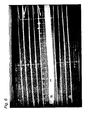
- Fig 6 shows a radiograph of a nail in alignment with a jig according to the invention where the camera is horizontal with respect to the jig.
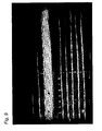
- Fig 7 shows the same arrangement before the jig has been moved into alignment with the nail.
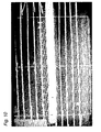
- Figs 8-11 show views of the aligned assembly taken from different camera angles, and confirm that whichever view is selected, the alignment between the nail and the jig is within acceptable tolerances.
- the arm can have (or can comprise) an extension to cover other faces of the limb; the extension can be in the form of an L-shaped or arcuate member being semi-cylindrical in form and typically describing 90°-180° of a circle.
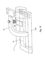
- One exemplary view of an extension can be seen in Fig 12 , which permits holes to be drilled at various angles relative to one another, and is particularly useful for nails that have dorso-ventral and medio-lateral (or other intermediate) fixing holes at the distal ends.
- the arm in the Fig 12 embodiment can be biased downwards and inwards relative to the limb, so that it needs to be moved in more than one plane to align the holes on the extension with the holes on the nail.
- wires/strips in the jigs need not be made from metal; any suitable radio-opaque material could be used instead.
- Figs 13 - 15 show an artero-posterior view of a knee joint into which a pin (not shown) is to be driven.
- Figs 14 and 15 show lateral and plan views of the joint respectively. The pin will be inserted through a hole drilled by a cannulated drill over a K-wire 30.
- the K-wire 30 is attached to a jig 50 having an arm 51, an L-shaped head 52 arranged perpendicular to the arm 51, a clamp 53 for a drill guide 31 or a K-wire 30, and a handle 54.
- the drill guide/K-wire clamp and the arm 51 are parallel to the X-axis shown in Figs 13 and 14 .
- the arm 51 is formed of radio-translucent carbon fibre and incorporates at least one radio-opaque metal wire or strip etc as previously described.
- the arm 51 is rigidly attached to the K-wire.
- the handle 54 is manipulated so that the wire 30 is inserted into the bone to be pinned.
- the angle of insertion of the wire 30 is judged by observing the superimposed image of the strips in the arm 51 against the x-ray image of the bone.
- the angle of insertion can be chosen to place the K-wire 30 or to drill the hole in the most dense parts of the bone. If the wire 30 is going to pass through the upper surface of the bone, the jig 50 can be rotated around the Z-axis, to correct the path of the wire 30. Likewise, if the path will extend through the side of the bone, the jig can be rotated around the Y-axis to correct the path.
- the jig 50 shown in Figs 13 - 15 can be used as a hand held guide without any requirement to attach the jig 50 to any part of the patient's body, to facilitate the accurate placement of guide wires, drills, screws and other fixings, with reference to anatomical landmarks, and not necessarily with reference to other implants in the body, such as bone nails or other implants.
- the jig can help the surgeon to identify the proposed path of insertion of the components or implants to be inserted.
- the arm 51 in this embodiment can also extend around the joint to be viewed, as shown in the dotted lines on Fig 15 , which indicates an optional arm extension portion 51a of carbon fibre that incorporates wires or strips as previously indicated.
- the extension portion 51a is rigidly attached to the arm 51 at 90°, and allows a further view to superimpose the markers on the extension portion 51a on the lateral view of the joint, and enable further adjustment.
- This modified embodiment is especially useful for situations where the position of the components need to be checked in more than one plane, e.g. hip fractures, spinal surgery, internal organs that have been radiologically enhanced with contrast agents.
- the arm may be axially extendible, e.g. by having a telescopically extending portion that can be selectively extended and retracted to adjust the length of arm.
- One or both of the nail 10 and the arm may also have additional holes 12, so that the extension of the arm can be altered to align a selected pair or set of holes 12 and 22.
- Fig 16 shows an additional embodiment similar to the second, but where the arm comprises first and second pieces 40, 41 that slide telescopically relative to one another along the X-axis of the arm.
- the arm terminates in a head 43 that has a radio-translucent window insert 43a of carbon fibre or Perspex TM upon which is inscribed a radio-opaque leaded pattern of bars on each face of the window.
- the head 43 can rotate around the X-axis.
- the patterns of bars on each face of the window insert 43a are offset with respect to one another and arranged to permit transmission of x-rays or light through the window only when the rotational position of the window around the X-axis is not precisely perpendicular to the nail 10.
- the offset patterns on the opposing faces of the window 43 overlap and occlude the window, preventing the transmission of x-rays or light, thereby confirming the correct rotational orientation of the window with respect to axis of the holes 12 in the nail.
- the arm 40 Since the arm 40 has the same resilient hinge arrangement at it's proximal end, the arm can thus be adjusted around the Z-axis. Certain modified embodiments similar to Fig 12 can also be produced with telescopic devices and can therefore be adjustable in three planes, including around the Y-axis.
- the rotational alignment of the head 43 is adjusted by the above method to ensure that the head is in the correct rotational alignment with the axis of the hole 12 in the nail.
- the window insert 43a can be removed from the head 43, and a variable height drill guide 44 can be inserted into the head 43 in its place.
- the drill guide 44 can be adjusted to align the hole on the guide with the hole on the nail and then locked in place on the head 43, before the hole is drilled.
- the lockable ratchet on the arm can be unlocked and the head 43 can be moved from the position shown in Fig 16 to the position shown in dotted lines where the hole on the guide 44 is in axial alignment with the proximal hole 12 on the nail 10.
- the rotational alignment can be checked again if desired, and the proximal hole can be drilled.
- a further modification is shown in which the head 43 is axially extendible and rotationally adjustable around the X-axis as before.
- the head 43 has a window insert 43a but in this embodiment an additional window insert 46a is mounted on an optional gimballed frame 46 that is rotationally adjustable around the Y-axis.
- the patterns of radio-opaque markings applied to the different sides of the windows can be various designs, with the proviso that the two patterns should in this embodiment complement one another to occlude the radiation only when the angle of light striking each window is precisely perpendicular to the plane of the window.
- Different patterns for each of the windows 43a, 46a are shown in Fig 17 .
- the head 43 can be axially moved to a starting position where the axial alignment is verified with the windows out of rotational alignment with the nail so that the radiation can pass through both windows. In this position, the axial positioning in verified by lining up the central marker of the window 43a with the axis of the hole in the nail.
- the head 43 can be rotated around the X-axis to improve the view of the nail 10.
- the ratchet 42 is locked, and the head 43 is rotated around the X-axis until the image of the hole 12 in the nail 10 is occluded through the pattern on the window 43a, indicating that the correct alignment has been achieved around the X-axis.
- the rotational position of the head around the X-axis is optionally locked at this point, and the window insert 43a is optionally removed.
- the gimballed frame 46 is then rotated around the y axis, until the image of the hole 12 in the nail 10 through the pattern of the window 46a is occluded, indicating that the correct alignment around the Y-axis has been achieved.
- the rotational alignment of the head 43 around the X-axis is checked with a first window insert, and the rotational alignment of the gimballed frame 46 around the Y-axis is then checked using a different insert, but in certain embodiments the rotational alignment around the 2 axes can be checked by using the same window insert.
- the head can be locked in position, the window removed and the drill guide 44 inserted in place, for drilling the hole through the bone.
- any x-ray emitter and detection device could alternatively be used to check the alignment of the nail and the jig.
- the apparatus could also be a jig used to correctly align a fracture-securing pin, such as a hip pin.
- the jig would typically be secured to the patient's bone or to the exterior of the body. Viewing the jig and bone through an image intensifier, the position of the jig could then be adjusted to align radio-opaque markings of the jig with the bone or a particular feature on the bone.
- a guide wire could then be inserted through a hole in the jig, and a drill used to drill a hole in the bone for insertion of the pin.
- the use of the guide wire is optional and the pin and/or drill may be cannulated to fit over the guide wire.
Abstract
Description
- The present invention relates to an assembly for aligning and positioning implants in a body, and is particularly useful for the positioning and securing of intra-medullary bone fixings such as nails.
- It is common practice to support fractures in long bones by intra-medullary nails. The nail is inserted into the medullary canal of the long bone, and is held in place by screws that are driven laterally through the bone at each end of the nail. The screws also pass through pre-drilled holes in the end of the intra-medullary nail, thereby reducing or preventing movement of the nail while the fracture is healing. Holes must be bored laterally through the bone in order to insert the screws, and these must be aligned with the pre-drilled holes in the ends of the intra-medullary nail. In order to position and drill the holes accurately in the bone, a jig is commonly employed.
- The jig is attached to the protruding (proximal) end of the nail after insertion of the nail into the medullary canal, and typically extends generally parallel to the nail. The jig has pre-drilled holes that align with the holes in nail when the jig and the nail are properly attached and aligned. This works quite satisfactorily for the proximal holes to be drilled through the bone, but since the jig is only attached to the nail at one end, and the jig and nail can be quite long (up to around 60cm), it can be very difficult to align the distal holes in the jig with the distal holes in the nail.
-
US-A-4976713 andUS-A-4803976 show jigs for securing intra-medullary nails. - According to the present invention which is defined by
claim 1, there is provided an assembly for handling of an implant for a body. - The assembly comprises a jig for positioning of implants such as fixings for bone nails, plates or other structural support devices inserted into a body.
- The radio-translucent portion can be formed of plastics material, but in preferred embodiments the jig is generally made from rigid materials, so materials such as carbon fibre are preferred. The radio-opaque marking can be one or more strips of metal (or other radio-opaque materials such as lead paint) applied to the carbon fibre, or incorporated therein. The radio-opaque markings are in the form of parallel lines. The markings can preferably be provided on the jig itself, but in some embodiments, the markings can be provided on a separate alignment device or guide that can be connected to the jig, or placed in a defined position relative to it.
- The jig typically has markings or guide holes to indicate positions on the bone to drill holes to receive fixing screws or other implants such as pins or wires. In preferred embodiments, the jig can receive drill sleeves to be placed against the bone so that holes can be drilled through the drill sleeves into the bone at a position on the bone that is aligned with the holes in the nail, or which hit a target in the bone e.g. the head of femur.
- The jig may have an alignment adjustment mechanism to adjust the alignment of the jig relative to the patient, and consequently relative to the nail inserted into the medullary canal of the bone in the limb, or other target on the patient. The alignment adjustment mechanism can typically comprise a screw-threaded device such as a screw-threaded shaft that can adjust the alignment of the nail and the jig in small increments. The shaft can engage within a screw thread on the jig, or a nut, and can terminate in a pad.
- The jig can typically have a hinge to allow movement of an arm of the jig having markings or guide holes to indicate the position of the holes to be drilled through the bone. The hinge can be in the form of a true hinge, or in the form of a semi-flexible joint having a degree of resilience.
- For use with intra-medullary nails, the jig may be attached to the nail. In some of these embodiments the jig can be deliberately misaligned with the nail at an initial position, so that the alignment of the jig and the nail must be adjusted by the adjustment mechanism before the correct alignment is achieved. In preferred embodiments, the distal end of the jig is inclined towards the nail, and/or out of the plane of the nail. Typically the jig is attached at only one end (e.g. the protruding end) of the nail, so that the lateral end of the jig can be moved into the correct alignment with the nail by the adjustment mechanism. This gives the advantage that the final aligned position of the jig relative to the nail is only reached after forcing the jig into that aligned position, against the resilience of the jig, which seeks to return the jig to the misaligned initial position. Therefore, the final aligned position is less prone to variation as a result of the opposing forces acting on the jig.
- Typically the jig is attached to one end of an intra-medullary bone fixing such as a nail, and the assembly is viewed through an x-ray image intensifier so that the radio-opaque markings on the jig can be superimposed upon the image of the bone fixing, which is typically also radio-opaque. The alignment between the distal end of the jig and the nail located in the medullary canal can then be checked and adjusted by slight movements of the jig relative to the limb of the patient, before the holes are drilled through the bone to insert the fixing screws through the nail.
- In a simple embodiment of the invention, the jig comprises a flat member that extends in a single plane that is generally parallel to the nail that is inserted into the medullary canal of the fractured bone. However, in certain more complex embodiments, the jig can be formed in more than one plane. For example, the jig can be generally L-shaped or arcuate (e.g. semi-cylindrical) instead of planar, and can extend circumferentially over different parts of the limb. Non-planar embodiments can typically extend around 90-180° (or more, eg up to 360°) of the limb, so that lateral holes can be drilled through the bone at various angles, allowing antero-posterior, medio-lateral and diagonal fixings to be inserted through the bone to connect with corresponding holes in the nail, or with other targets in the patient.
- The implant to be handled is preferably a fixing for an intra-medullary nail, but other implants of a permanent or of a more transitory nature can also be handled with the assembly, such as drill bits, guide wires for drills, screws such as bone screws, k-wires, blade plates and pins such as external fixator pins etc. Certain embodiments of the invention are particularly suitable for correct placing of implants that are not visible on X-rays. The assembly is also very useful for image guided surgical procedures, where, for example, a hole must be drilled along a very precise path into e.g. a spinal vertebra, for injection of e.g. hydroxyappatite paste into the bone, and is particularly useful for surgical procedures where there is very little margin for error. Using the assembly, the path of the drill can be visualised e.g. by X-rays before the hole is drilled, thereby increasing the accuracy of the drilling, and reducing the risks to the patient.
- A method of aligning a jig with a body implant is also shown, the method comprising providing a radio-translucent portion of the jig with radio-opaque markings, and assessing alignment of the jig and the body implant by observing the alignment of the body implant relative to the radio-opaque markings.
- The jig can be hand-held or can be adapted to be attached to the body, either to the surface of the body or to a portion of the skeleton. In some embodiments the jig can be attached to wires or pins braced against the surface of the bone, or to a frame attached to such wires or pins.
-
Fig 1 shows a schematic perspective view of a first jig; -
Fig 2 shows a similar view of a second jig; -
Fig 3 shows a close up view of theFig 1 and Fig 2 jig; -
Fig 4 shows the jig misaligned with the nail; -
Fig 5 shows the jig and nail properly aligned; -
Fig 6 is a radiograph of a nail aligned with a jig; -
Fig 7 is a radiograph of a nail misaligned with a jig; -
Fig 8 is a view similar toFig 6 with the camera displaced 20° down; -
Fig 9 is a view similar toFig 6 with the camera displaced 15° up; -
Fig 10 is a view similar toFig 6 , with the camera horizontal but displaced 15° craniocaudally; -
Fig 11 is a view similar toFig 6 , with the camera rotated 30° down and displaced 15° craniocaudally; and -
Fig 12 is a view similar toFig 2 showing a further jig with an extension; -
Figs 13, 14 and15 show a further embodiment of the assembly for use with a guide wire, unattached to the patient's skeleton; -
Fig 16 shows a portion of a further embodiment of a jig with the capability of axial extension of a bar; and -
Fig 17 shows a portion of a further embodiment of a jig with the capability of rotational movement of the distal end in more than one plane. - Referring now to
Fig 1 , anintra-medullary nail 10 adapted to be inserted into the medullary canal of a long bone has a proximal end attached to ajig 20, and a distal end withholes 12 to receive fixing screws (not shown). Thejig 20 has ahead portion 20h adapted to attach releasably to the proximal end of thenail 10 by means of a bolt (not shown) driven through thehead 20h and into an axial socket on thenail 10. Thejig 20 also has anarm 20a that is attached to thehead 20h by a hinge having aratchet 24 allowing the angle of thearm 20a to be varied relative to thenail 10. The hinge can optionally incorporate a locking mechanism to lock thearm 20a at a predetermined attitude relative to thenail 10, and this arrangement can usefully replace theratchet mechanism 24. - The
arm 20a of the jig has a pair ofholes 22 in the distal end (there could be any number of holes provided). Thedistal holes 22 in thearm 20a align with thedistal holes 12 in thenail 10 when thearm 20a is aligned with thenail 10. Theholes 22 are each adapted to receive a drill sleeve through which a drill bit can be inserted in order to drill a hole through the bone in alignment with theholes 12 in thenail 10. - The
arm 20a is formed from carbon fibre, but another material that is radio-translucent could alternatively be used. Thearm 20a hasmetal wires 26 embedded within it, or attached to one of its lateral surfaces. Thewires 26 are generally disposed in a parallel array along the length of thearm 20a, although it should be noted that other patterns of markers can optionally be used, and parallel arrays are not essential. Since the metal wires are radio-opaque, they are distinguishable when the assembly of the jig and nail are viewed in a x-ray image intensifier, or other x-ray detection device. - As an alternative to axial metal wires, planar metal strips (not shown) could be embedded within the
arm 20a parallel to the axis of the arm. The metal strips could be aligned in horizontal planes vertically spaced from each other in the arm. Such strips would appear as narrow lines if the nearest face ofarm 20a is oriented exactly perpendicular to the beam from the image intensifier. However, if thearm 20a is misaligned, the strips would appear as thicker rectangles. Thus, such metal strips provide the advantage of allowing judgement of the rotational alignment of the arm, and hence also of the nail, as well as the axial alignment of the nail. - The planar metal strips could also be arranged in the plane of the axis of the arm and in another plane perpendicular thereto, so that the two sets of lines interconnect with one another. In this embodiment the grid of strips can indicate alignment in more than one plane by presenting a minimal cross-section to the viewer, and can indicate misalignment by increased cross-section of the observed grid.
- In use, the
intra-medullary nail 10 is inserted into the medullary canal of the patient's limb and thejig 20 attached to its proximal end. Initially, thearm 20a is placed out of alignment with thenail 10, and the view through the image intensifier is similar to that shown inFig 4 , where thenail 10 is seen superimposed upon the parallel array ofwires 26, and the misalignment between thenail 10 and thejig arm 20a is apparent. Thearm 20a is then pivoted around the hinge relative to thenail 10 until the parallel array ofwires 26 is aligned with thenail 10 in the image intensifier, as shown inFig 5 . When thearm 20a is in the position shown inFig 5 , with the parallel array ofwires 26 being aligned with thenail 10, the operator can be sure that theholes 22 in the jig are aligned perfectly with theholes 12 in thenail 10. It should be noted that the markings on the arm need only be brought into alignment with a part of the nail, or with other markings on the nail, and that the whole of the nail does not need to be aligned with the markings on the jig, in order to verify its correct position. - When the
holes 22 are perfectly aligned withholes 12, theratchet 24 is adjusted to fix the angle of thearm 20a relative to thenail 10. Typically, guide wires (K-wires) are now inserted throughholes 22 and holes 12 and are secured in the cortical bone on the opposite side of the bone to thejig 20. A cannulated drill is then inserted over the guide wires to drill holes through the bone. The holes preferably extend as far as the cortical bone on the far side of the bone from thejig 20. The drill is then removed and cannulated screws are inserted over the guide wires and screwed into the bone to secure thenail 10 to the bone.Jig 20 is then detached from thenail 10, and thenail 10 is typically left in the bone until the fracture has healed. - The above-described method is a preferred method of operation; however, modifications may be made. It is not necessary to use the guide wires, as the
holes -
Fig 2 shows an alternative embodiment of a jig 21 in which thearm 21a is attached to thehead 21h by means of a semi-flexible joint 25. Thearm 21a is again formed from carbon fibre, and hasmetallic wires 26 similar to the first embodiment shown inFig 1 . TheFig 2 embodiment also has astabiliser arm 27 with a threaded shaft passing through a plain aperture in thearm 27, and terminating in apadded foot 29. Thearm 21a is biased out of alignment with thenail 10 so that the two initially adopt relative positions similar to those shown inFig 4 . In use, thefoot 29 is placed on top of the patient's limb and anut 28 adjusted to push the limb of the patient down relative to thearm 21a. Since thenail 10 is embedded within the medullary canal of the long bone in the patient's limb, this has the effect of bringing thearm 21a and thenail 10 into alignment. Thenut 28 is driven up the shaft until thearm 21a and thenail 10 are pulled into the position shown inFig 5 , where themetal wires 26 can be seen to be in alignment with thenail 10. At this point, in a similar manner to theFig 1 embodiment, the alignment of thenail 10 and the arm 21 can be verified, and the drill sleeves can be inserted through theholes 22, and holes drilled through the bone with confidence that they are aligned with theholes 12 in the distal end of thenail 10. - The method steps described above with reference to
Fig. 1 concerning insertion of guide wires, drilling holes in the bone with a cannulated drill inserted over the guide wires and inserting screws to secure thenail 10 to the bone are all equally applicable here. - This embodiment has additional advantages over the
Fig 1 design, in that the contact between thestabiliser arm 27 and the limb helps to maintain the alignment, and reduces the likelihood of force exerted by the weight of the drill, or force misapplied by the operator, moving thearm 21a out of alignment with thenail 10 during the drilling procedure. In addition, the deliberate bias of thearm 21a out of alignment with thenail 10 forces the operator to observe the alignment of thenail 10 and thearm 21a until the two are properly aligned with one another. Furthermore, since thearm 21a is subject to opposing forces exerted by thestabiliser arm 27 on the one hand and the natural bias of the semi-flexible joint 25 on the other, it is less likely to deviate from its position once alignment has been established. -
Fig 6 shows a radiograph of a nail in alignment with a jig according to the invention where the camera is horizontal with respect to the jig.Fig 7 shows the same arrangement before the jig has been moved into alignment with the nail.Figs 8-11 show views of the aligned assembly taken from different camera angles, and confirm that whichever view is selected, the alignment between the nail and the jig is within acceptable tolerances. - Modifications and improvements can be incorporated without departing from the scope of the invention. For example, in a complex version of the invention the arm can have (or can comprise) an extension to cover other faces of the limb; the extension can be in the form of an L-shaped or arcuate member being semi-cylindrical in form and typically describing 90°-180° of a circle. One exemplary view of an extension can be seen in
Fig 12 , which permits holes to be drilled at various angles relative to one another, and is particularly useful for nails that have dorso-ventral and medio-lateral (or other intermediate) fixing holes at the distal ends. The arm in theFig 12 embodiment can be biased downwards and inwards relative to the limb, so that it needs to be moved in more than one plane to align the holes on the extension with the holes on the nail. - This can be achieved by providing more than one stabiliser arm; for example a second stabiliser arm that pushes the distal ends of the arm and the limb away from one another; or by locating the stabiliser arm at an intermediate position between the horizontal and vertical positions.
- The wires/strips in the jigs need not be made from metal; any suitable radio-opaque material could be used instead.
- Certain embodiments of the invention do not need to have the jig physically attached to either the nail or the skeleton of the patient. For example, the jig could be hand held or could be adapted to firmly attach to the outside of the patient's limb and an image intensifier used to check that the jig is correctly aligned with the patient's bone. One such embodiment is shown in
Figs 13 - 15 .Fig 13 shows an artero-posterior view of a knee joint into which a pin (not shown) is to be driven.Figs 14 and15 show lateral and plan views of the joint respectively. The pin will be inserted through a hole drilled by a cannulated drill over a K-wire 30. The K-wire 30 is attached to ajig 50 having anarm 51, an L-shapedhead 52 arranged perpendicular to thearm 51, aclamp 53 for adrill guide 31 or a K-wire 30, and ahandle 54. The drill guide/K-wire clamp and thearm 51 are parallel to the X-axis shown inFigs 13 and 14 . Thearm 51 is formed of radio-translucent carbon fibre and incorporates at least one radio-opaque metal wire or strip etc as previously described. Thearm 51 is rigidly attached to the K-wire. - In use, the
handle 54 is manipulated so that thewire 30 is inserted into the bone to be pinned. The angle of insertion of thewire 30 is judged by observing the superimposed image of the strips in thearm 51 against the x-ray image of the bone. The angle of insertion can be chosen to place the K-wire 30 or to drill the hole in the most dense parts of the bone. If thewire 30 is going to pass through the upper surface of the bone, thejig 50 can be rotated around the Z-axis, to correct the path of thewire 30. Likewise, if the path will extend through the side of the bone, the jig can be rotated around the Y-axis to correct the path. - The
jig 50 shown inFigs 13 - 15 can be used as a hand held guide without any requirement to attach thejig 50 to any part of the patient's body, to facilitate the accurate placement of guide wires, drills, screws and other fixings, with reference to anatomical landmarks, and not necessarily with reference to other implants in the body, such as bone nails or other implants. The jig can help the surgeon to identify the proposed path of insertion of the components or implants to be inserted. - The
arm 51 in this embodiment can also extend around the joint to be viewed, as shown in the dotted lines onFig 15 , which indicates an optionalarm extension portion 51a of carbon fibre that incorporates wires or strips as previously indicated. Theextension portion 51a is rigidly attached to thearm 51 at 90°, and allows a further view to superimpose the markers on theextension portion 51a on the lateral view of the joint, and enable further adjustment. This modified embodiment is especially useful for situations where the position of the components need to be checked in more than one plane, e.g. hip fractures, spinal surgery, internal organs that have been radiologically enhanced with contrast agents. - In some embodiments, the arm may be axially extendible, e.g. by having a telescopically extending portion that can be selectively extended and retracted to adjust the length of arm. One or both of the
nail 10 and the arm may also haveadditional holes 12, so that the extension of the arm can be altered to align a selected pair or set ofholes -
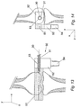
Fig 16 shows an additional embodiment similar to the second, but where the arm comprises first andsecond pieces head 43 that has a radio-translucent window insert 43a of carbon fibre or Perspex TM upon which is inscribed a radio-opaque leaded pattern of bars on each face of the window. In addition to being able to move axially along the X-axis of the arm, thehead 43 can rotate around the X-axis. The patterns of bars on each face of thewindow insert 43a are offset with respect to one another and arranged to permit transmission of x-rays or light through the window only when the rotational position of the window around the X-axis is not precisely perpendicular to thenail 10. When thehead 43 is precisely perpendicular to the nail, the offset patterns on the opposing faces of thewindow 43 overlap and occlude the window, preventing the transmission of x-rays or light, thereby confirming the correct rotational orientation of the window with respect to axis of theholes 12 in the nail. - Since the
arm 40 has the same resilient hinge arrangement at it's proximal end, the arm can thus be adjusted around the Z-axis. Certain modified embodiments similar toFig 12 can also be produced with telescopic devices and can therefore be adjustable in three planes, including around the Y-axis. - When the
head 43 has been moved to the correct axial position so that an optional radio-opaque marker in the centre of the window is axially aligned with the desired hole in the nail, the rotational alignment of thehead 43 is adjusted by the above method to ensure that the head is in the correct rotational alignment with the axis of thehole 12 in the nail. At that point thewindow insert 43a can be removed from thehead 43, and a variableheight drill guide 44 can be inserted into thehead 43 in its place. Thedrill guide 44 can be adjusted to align the hole on the guide with the hole on the nail and then locked in place on thehead 43, before the hole is drilled. - When the first hole is drilled, e.g. for the
distal hole 12 on thenail 10, the lockable ratchet on the arm can be unlocked and thehead 43 can be moved from the position shown inFig 16 to the position shown in dotted lines where the hole on theguide 44 is in axial alignment with theproximal hole 12 on thenail 10. The rotational alignment can be checked again if desired, and the proximal hole can be drilled. - In the
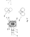
Fig 17 embodiment, a further modification is shown in which thehead 43 is axially extendible and rotationally adjustable around the X-axis as before. Thehead 43 has awindow insert 43a but in this embodiment anadditional window insert 46a is mounted on anoptional gimballed frame 46 that is rotationally adjustable around the Y-axis. - The patterns of radio-opaque markings applied to the different sides of the windows can be various designs, with the proviso that the two patterns should in this embodiment complement one another to occlude the radiation only when the angle of light striking each window is precisely perpendicular to the plane of the window. Different patterns for each of the
windows Fig 17 . - The
head 43 can be axially moved to a starting position where the axial alignment is verified with the windows out of rotational alignment with the nail so that the radiation can pass through both windows. In this position, the axial positioning in verified by lining up the central marker of thewindow 43a with the axis of the hole in the nail. Thehead 43 can be rotated around the X-axis to improve the view of thenail 10. When the desired axial alignment is achieved, theratchet 42 is locked, and thehead 43 is rotated around the X-axis until the image of thehole 12 in thenail 10 is occluded through the pattern on thewindow 43a, indicating that the correct alignment has been achieved around the X-axis. The rotational position of the head around the X-axis is optionally locked at this point, and thewindow insert 43a is optionally removed. Thegimballed frame 46 is then rotated around the y axis, until the image of thehole 12 in thenail 10 through the pattern of thewindow 46a is occluded, indicating that the correct alignment around the Y-axis has been achieved. In this embodiment the rotational alignment of thehead 43 around the X-axis is checked with a first window insert, and the rotational alignment of thegimballed frame 46 around the Y-axis is then checked using a different insert, but in certain embodiments the rotational alignment around the 2 axes can be checked by using the same window insert. - When the correct axial and rotational alignment has been achieved, the head can be locked in position, the window removed and the
drill guide 44 inserted in place, for drilling the hole through the bone. - These embodiments can share all of the features of the other embodiments
- Although the use of an image intensifier is described above, any x-ray emitter and detection device could alternatively be used to check the alignment of the nail and the jig.
- Although the apparatus described here has two
holes 12 and twofurther holes 22, different holes could be provided as required. - It should be noted that not all embodiments of the invention need to be used in conjunction with an intra-medullary nail. For example, the apparatus could also be a jig used to correctly align a fracture-securing pin, such as a hip pin. The jig would typically be secured to the patient's bone or to the exterior of the body. Viewing the jig and bone through an image intensifier, the position of the jig could then be adjusted to align radio-opaque markings of the jig with the bone or a particular feature on the bone. A guide wire could then be inserted through a hole in the jig, and a drill used to drill a hole in the bone for insertion of the pin. As in the embodiments described above, the use of the guide wire is optional and the pin and/or drill may be cannulated to fit over the guide wire.
Claims (22)
- An assembly comprising:a jig (20) for handling of at least one implant for insertion into a patient's body; anda support device (10) for insertion into the patient's body, the support device (10) having a longitudinal axis;wherein the jig (20) has a proximal end (20h) adapted to connect to a proximal end of the support device (10) and a distal end that is moveable with respect to the proximal end (20h);
characterised in that the distal end of the jig (20) has a radio-translucent portion and a plurality of parallel, radio-opaque markings (26);
wherein, in use, the distal end of the jig (20) can be moved relative to the proximal end (20h), with the radio-opaque markings (26) indicating an aligned position, in which the radio-opaque markings (26) of the jig (20) are aligned with the longitudinal axis of the support device (10). - An assembly, as claimed in claim 1, wherein the jig (20), has at least one rigid portion.
- An assembly, as claimed in any preceding claim,
wherein the radio-opaque markings (26) comprise strips or lines applied to the jig (20), or incorporated therein. - An assembly, as claimed in any preceding claim, wherein the radio-opaque markings (26) indicate the position to drill a respective hole to receive the at least one implant.
- An assembly, as claimed in any preceding claim, wherein the jig (20), is adapted to receive a drill or a drill sleeve and/or a guide wire.
- An assembly, as claimed in any preceding claim, affixable to the body of the patient.
- An assembly, as claimed in any preceding claim, wherein the support device (10) comprises an intra-medullary nail to be placed in the medullary canal of the bone of a limb of a patient.
- An assembly, as claimed in any preceding claim, wherein the jig (20), has an alignment adjustment mechanism (24) to adjust the alignment of the jig (20), relative to the body and/or the support device (10).
- An assembly, as claimed in claim 8, wherein the alignment adjustment mechanism (24) comprises a screw-threaded device that can adjust the alignment of the jig (20), in small increments.
- An assembly, as claimed in claim 8 or claim 9, wherein the jig (20), is adapted to be attached to the support device (10) at only its proximal end (20h), and wherein the adjustment mechanism (24) is adapted to move the distal end of the jig (20) into alignment with the body and/or the support device (10).
- An assembly, as claimed in any preceding claim, wherein the jig (20), is resiliently biased out of alignment with the body and/or the support device (10).
- An assembly, as claimed in any preceding claim, wherein the distal end of the jig (20), is inclined towards the body and/or the support device (10).
- An assembly, as claimed in any preceding claim, wherein the distal, end of the jig (20), is inclined out of the plane of the body and/or the support device (10).
- An assembly, as claimed in any preceding claim, wherein the jig (20), extends circumferentially around the body to allow lateral holes to be drilled through the body at different angles.
- An assembly, as claimed in any preceding claim, wherein the jig (20) comprises a generally planar member that extends in a single plane that is parallel to the support device (10).
- An assembly, as claimed in any preceding claim, wherein the jig (20), has an arm (20a) and a hinge to allow movement of the arm (20a).
- An assembly, as claimed in claim 16, wherein the hinge is a resilient joint (25).
- An assembly, as claimed in claim 16, or 17, wherein the arm (21a) is formed in more than one plane.
- An assembly, as claimed in any one of clams 16, to 18, wherein the arm (21a) is L-shaped or arcuate.
- An assembly, as claimed in any of claims 16 to 19, wherein the arm (20a) is extendible.
- An assembly, as claimed in any preceding claim, wherein the implant to be handled is a fixing for an intra-medullary nail.
- An assembly, as claimed in claim 21, wherein the implant is selected from the group comprising antero-posterior, medio-lateral and diagonal fixings.
Priority Applications (1)
| Application Number | Priority Date | Filing Date | Title |
|---|---|---|---|
| EP09171697A EP2151203A3 (en) | 2002-04-27 | 2003-04-28 | Apparatus and method for aligning and positioning implants in a body |
Applications Claiming Priority (3)
| Application Number | Priority Date | Filing Date | Title |
|---|---|---|---|
| GB0209719 | 2002-04-27 | ||
| GBGB0209719.4A GB0209719D0 (en) | 2002-04-27 | 2002-04-27 | Apparatus and method |
| PCT/GB2003/001794 WO2003092515A2 (en) | 2002-04-27 | 2003-04-28 | Apparatus and method for aligning and positioning implants in a body |
Related Child Applications (1)
| Application Number | Title | Priority Date | Filing Date |
|---|---|---|---|
| EP09171697A Division EP2151203A3 (en) | 2002-04-27 | 2003-04-28 | Apparatus and method for aligning and positioning implants in a body |
Publications (2)
| Publication Number | Publication Date |
|---|---|
| EP1499249A2 EP1499249A2 (en) | 2005-01-26 |
| EP1499249B1 true EP1499249B1 (en) | 2009-09-30 |
Family
ID=9935676
Family Applications (2)
| Application Number | Title | Priority Date | Filing Date |
|---|---|---|---|
| EP09171697A Withdrawn EP2151203A3 (en) | 2002-04-27 | 2003-04-28 | Apparatus and method for aligning and positioning implants in a body |
| EP03747501A Expired - Lifetime EP1499249B1 (en) | 2002-04-27 | 2003-04-28 | Apparatus for aligning and positioning implants in a body |
Family Applications Before (1)
| Application Number | Title | Priority Date | Filing Date |
|---|---|---|---|
| EP09171697A Withdrawn EP2151203A3 (en) | 2002-04-27 | 2003-04-28 | Apparatus and method for aligning and positioning implants in a body |
Country Status (9)
| Country | Link |
|---|---|
| US (1) | US8568421B2 (en) |
| EP (2) | EP2151203A3 (en) |
| AT (1) | ATE444021T1 (en) |
| AU (1) | AU2003232312A1 (en) |
| DE (1) | DE60329481D1 (en) |
| DK (1) | DK1499249T3 (en) |
| ES (1) | ES2334024T3 (en) |
| GB (1) | GB0209719D0 (en) |
| WO (1) | WO2003092515A2 (en) |
Families Citing this family (17)
| Publication number | Priority date | Publication date | Assignee | Title |
|---|---|---|---|---|
| GB0209719D0 (en) | 2002-04-27 | 2002-06-05 | Grampian Univ Hospitals | Apparatus and method |
| GB0308367D0 (en) * | 2003-04-11 | 2003-05-14 | Khetrapal Ravi K | Improved locking of intramedullary fixation devices |
| GB0320375D0 (en) * | 2003-08-30 | 2003-10-01 | Grampian Univ Hospitals | Apparatus and method |
| US7406775B2 (en) * | 2004-04-22 | 2008-08-05 | Archus Orthopedics, Inc. | Implantable orthopedic device component selection instrument and methods |
| US7481815B2 (en) | 2004-09-23 | 2009-01-27 | Synthes (U.S.A.) | Coplanar X-ray guided aiming arm for locking of intramedullary nails |
| US9192398B2 (en) | 2005-09-19 | 2015-11-24 | DePuy Synthes Products, Inc. | Orthopedic implant insertion handle and aiming guide |
| US20070129630A1 (en) * | 2005-12-07 | 2007-06-07 | Shimko Daniel A | Imaging method, device and system |
| US20070135706A1 (en) * | 2005-12-13 | 2007-06-14 | Shimko Daniel A | Debridement method, device and kit |
| US7998180B2 (en) * | 2006-04-28 | 2011-08-16 | Warsaw Orthopedic, Inc. | Radiolucent bone plate systems and methods of use |
| US8685034B2 (en) * | 2006-08-10 | 2014-04-01 | Stryker Trauma Gmbh | Distal targeting device |
| DE102006058937A1 (en) * | 2006-12-12 | 2008-06-19 | Gottfried Wilhelm Leibniz Universität Hannover | Drill for surgical purposes |
| CN101801288B (en) * | 2007-09-13 | 2013-05-01 | 新特斯有限责任公司 | Aiming arm for locking of bone nails |
| US9907582B1 (en) | 2011-04-25 | 2018-03-06 | Nuvasive, Inc. | Minimally invasive spinal fixation system and related methods |
| CA2837205A1 (en) | 2011-05-25 | 2012-11-29 | DePuy Synthes Products, LLC | Aiming device having radio-opaque markers |
| ITBO20110481A1 (en) | 2011-08-01 | 2013-02-02 | Citieffe Srl | POSITIONER DEVICE FOR FIXING SCREWS OF AN ENDOMIDOLLAR NAIL. |
| WO2014194965A1 (en) | 2013-06-07 | 2014-12-11 | Stryker Trauma Gmbh | Targeting adjustment system for an intramedullary nail |
| US9763681B2 (en) | 2014-06-04 | 2017-09-19 | Biomet Manufacturing, Llc | Orthopaedic aiming device for compound screw trajectories |
Family Cites Families (10)
| Publication number | Priority date | Publication date | Assignee | Title |
|---|---|---|---|---|
| EP0187283B1 (en) | 1984-12-26 | 1989-04-26 | Nivarox-FAR S.A. | Device to locate in situ through-holes in a hollow pin that is implanted into the medullary canal for the retention of the fragments of a fractured bone |
| US4667664A (en) * | 1985-01-18 | 1987-05-26 | Richards Medical Company | Blind hole targeting device for orthopedic surgery |
| CH671873A5 (en) * | 1985-10-03 | 1989-10-13 | Synthes Ag | |
| US4969889A (en) * | 1986-12-22 | 1990-11-13 | Zimmer, Inc. | Instrument for locating a hole |
| FR2634641A1 (en) * | 1988-07-28 | 1990-02-02 | Michel Jean Pierre | DEVICE FOR THE POSITIONING OF AT LEAST ONE FIXING MEMBER THROUGH AN IMPLANT, OF THE CENTRO-MEDULINAL NAIL TYPE |
| US5766179A (en) * | 1997-03-05 | 1998-06-16 | Orthofix S.R.L. | Mechanical system for blind nail-hole alignment of bone screws |
| US6036696A (en) * | 1997-12-19 | 2000-03-14 | Stryker Technologies Corporation | Guide-pin placement device and method of use |
| US6656189B1 (en) * | 2000-05-25 | 2003-12-02 | Synthes (Usa) | Radiolucent aiming guide |
| WO2003063682A2 (en) * | 2002-01-25 | 2003-08-07 | Depuy Products, Inc. | Extramedullary fluoroscopic alignment guide |
| GB0209719D0 (en) | 2002-04-27 | 2002-06-05 | Grampian Univ Hospitals | Apparatus and method |
-
2002
- 2002-04-27 GB GBGB0209719.4A patent/GB0209719D0/en not_active Ceased
-
2003
- 2003-04-28 WO PCT/GB2003/001794 patent/WO2003092515A2/en not_active Application Discontinuation
- 2003-04-28 EP EP09171697A patent/EP2151203A3/en not_active Withdrawn
- 2003-04-28 ES ES03747501T patent/ES2334024T3/en not_active Expired - Lifetime
- 2003-04-28 AU AU2003232312A patent/AU2003232312A1/en not_active Abandoned
- 2003-04-28 DE DE60329481T patent/DE60329481D1/en not_active Expired - Lifetime
- 2003-04-28 DK DK03747501.9T patent/DK1499249T3/en active
- 2003-04-28 EP EP03747501A patent/EP1499249B1/en not_active Expired - Lifetime
- 2003-04-28 US US10/512,759 patent/US8568421B2/en active Active
- 2003-04-28 AT AT03747501T patent/ATE444021T1/en active
Also Published As
| Publication number | Publication date |
|---|---|
| ES2334024T3 (en) | 2010-03-04 |
| GB0209719D0 (en) | 2002-06-05 |
| WO2003092515A3 (en) | 2004-02-26 |
| ATE444021T1 (en) | 2009-10-15 |
| EP2151203A3 (en) | 2010-05-05 |
| DK1499249T3 (en) | 2010-01-18 |
| EP1499249A2 (en) | 2005-01-26 |
| DE60329481D1 (en) | 2009-11-12 |
| US8568421B2 (en) | 2013-10-29 |
| AU2003232312A8 (en) | 2003-11-17 |
| US20050177175A1 (en) | 2005-08-11 |
| WO2003092515A2 (en) | 2003-11-13 |
| AU2003232312A1 (en) | 2003-11-17 |
| EP2151203A2 (en) | 2010-02-10 |
Similar Documents
| Publication | Publication Date | Title |
|---|---|---|
| EP1499249B1 (en) | Apparatus for aligning and positioning implants in a body | |
| US10820916B2 (en) | Coplanar X-ray guided aiming arm for locking of intramedullary nails | |
| EP2049025B1 (en) | Distal targeting device | |
| JP3280631B2 (en) | Orthopedic targeting device, arm-like device and angular guide device for the device | |
| KR101363848B1 (en) | Aiming device | |
| EP1350479B1 (en) | Fastener and targeting device for an intra-medullary nail | |
| US4667664A (en) | Blind hole targeting device for orthopedic surgery | |
| KR20160146957A (en) | Aiming device for distal locking of intramedullary nails and methods of use | |
| US20110184477A1 (en) | Aiming Arm for Locking of Bone Nails | |
| US20140249536A1 (en) | Distal locking targeting device | |
| US20210015500A1 (en) | System and method for placing fasteners into intramedullary nails | |
| ES2360762T3 (en) | DISTAL ADDRESS DEVICE. |
Legal Events
| Date | Code | Title | Description |
|---|---|---|---|
| PUAI | Public reference made under article 153(3) epc to a published international application that has entered the european phase |
Free format text: ORIGINAL CODE: 0009012 |
|
| 17P | Request for examination filed |
Effective date: 20041009 |
|
| AK | Designated contracting states |
Kind code of ref document: A2 Designated state(s): AT BE BG CH CY CZ DE DK EE ES FI FR GB GR HU IE IT LI LU MC NL PT RO SE SI SK TR |
|
| AX | Request for extension of the european patent |
Extension state: AL LT LV MK |
|
| RAP1 | Party data changed (applicant data changed or rights of an application transferred) |
Owner name: GRAMPIAN HEALTH BOARD |
|
| 17Q | First examination report despatched |
Effective date: 20070703 |
|
| GRAP | Despatch of communication of intention to grant a patent |
Free format text: ORIGINAL CODE: EPIDOSNIGR1 |
|
| RTI1 | Title (correction) |
Free format text: APPARATUS FOR ALIGNING AND POSITIONING IMPLANTS IN A BODY |
|
| GRAS | Grant fee paid |
Free format text: ORIGINAL CODE: EPIDOSNIGR3 |
|
| GRAA | (expected) grant |
Free format text: ORIGINAL CODE: 0009210 |
|
| AK | Designated contracting states |
Kind code of ref document: B1 Designated state(s): AT BE BG CH CY CZ DE DK EE ES FI FR GB GR HU IE IT LI LU MC NL PT RO SE SI SK TR |
|
| REG | Reference to a national code |
Ref country code: CH Ref legal event code: EP Ref country code: GB Ref legal event code: FG4D |
|
| REG | Reference to a national code |
Ref country code: IE Ref legal event code: FG4D |
|
| REF | Corresponds to: |
Ref document number: 60329481 Country of ref document: DE Date of ref document: 20091112 Kind code of ref document: P |
|
| REG | Reference to a national code |
Ref country code: CH Ref legal event code: NV Representative=s name: MURGITROYD & COMPANY |
|
| REG | Reference to a national code |
Ref country code: SE Ref legal event code: TRGR |
|
| REG | Reference to a national code |
Ref country code: DK Ref legal event code: T3 |
|
| PG25 | Lapsed in a contracting state [announced via postgrant information from national office to epo] |
Ref country code: FI Free format text: LAPSE BECAUSE OF FAILURE TO SUBMIT A TRANSLATION OF THE DESCRIPTION OR TO PAY THE FEE WITHIN THE PRESCRIBED TIME-LIMIT Effective date: 20090930 |
|
| PG25 | Lapsed in a contracting state [announced via postgrant information from national office to epo] |
Ref country code: SI Free format text: LAPSE BECAUSE OF FAILURE TO SUBMIT A TRANSLATION OF THE DESCRIPTION OR TO PAY THE FEE WITHIN THE PRESCRIBED TIME-LIMIT Effective date: 20090930 |
|
| REG | Reference to a national code |
Ref country code: ES Ref legal event code: FG2A Ref document number: 2334024 Country of ref document: ES Kind code of ref document: T3 |
|
| PG25 | Lapsed in a contracting state [announced via postgrant information from national office to epo] |
Ref country code: RO Free format text: LAPSE BECAUSE OF FAILURE TO SUBMIT A TRANSLATION OF THE DESCRIPTION OR TO PAY THE FEE WITHIN THE PRESCRIBED TIME-LIMIT Effective date: 20090930 Ref country code: PT Free format text: LAPSE BECAUSE OF FAILURE TO SUBMIT A TRANSLATION OF THE DESCRIPTION OR TO PAY THE FEE WITHIN THE PRESCRIBED TIME-LIMIT Effective date: 20100201 Ref country code: CZ Free format text: LAPSE BECAUSE OF FAILURE TO SUBMIT A TRANSLATION OF THE DESCRIPTION OR TO PAY THE FEE WITHIN THE PRESCRIBED TIME-LIMIT Effective date: 20090930 Ref country code: EE Free format text: LAPSE BECAUSE OF FAILURE TO SUBMIT A TRANSLATION OF THE DESCRIPTION OR TO PAY THE FEE WITHIN THE PRESCRIBED TIME-LIMIT Effective date: 20090930 |
|
| PG25 | Lapsed in a contracting state [announced via postgrant information from national office to epo] |
Ref country code: CY Free format text: LAPSE BECAUSE OF FAILURE TO SUBMIT A TRANSLATION OF THE DESCRIPTION OR TO PAY THE FEE WITHIN THE PRESCRIBED TIME-LIMIT Effective date: 20090930 Ref country code: SK Free format text: LAPSE BECAUSE OF FAILURE TO SUBMIT A TRANSLATION OF THE DESCRIPTION OR TO PAY THE FEE WITHIN THE PRESCRIBED TIME-LIMIT Effective date: 20090930 |
|
| PLBE | No opposition filed within time limit |
Free format text: ORIGINAL CODE: 0009261 |
|
| STAA | Information on the status of an ep patent application or granted ep patent |
Free format text: STATUS: NO OPPOSITION FILED WITHIN TIME LIMIT |
|
| 26N | No opposition filed |
Effective date: 20100701 |
|
| PG25 | Lapsed in a contracting state [announced via postgrant information from national office to epo] |
Ref country code: GR Free format text: LAPSE BECAUSE OF FAILURE TO SUBMIT A TRANSLATION OF THE DESCRIPTION OR TO PAY THE FEE WITHIN THE PRESCRIBED TIME-LIMIT Effective date: 20091231 |
|
| PG25 | Lapsed in a contracting state [announced via postgrant information from national office to epo] |
Ref country code: MC Free format text: LAPSE BECAUSE OF NON-PAYMENT OF DUE FEES Effective date: 20100430 |
|
| PG25 | Lapsed in a contracting state [announced via postgrant information from national office to epo] |
Ref country code: IT Free format text: LAPSE BECAUSE OF NON-PAYMENT OF DUE FEES Effective date: 20100428 |
|
| PGFP | Annual fee paid to national office [announced via postgrant information from national office to epo] |
Ref country code: LU Payment date: 20110426 Year of fee payment: 9 |
|
| PGFP | Annual fee paid to national office [announced via postgrant information from national office to epo] |
Ref country code: IE Payment date: 20110420 Year of fee payment: 9 |
|
| PGRI | Patent reinstated in contracting state [announced from national office to epo] |
Ref country code: IT Effective date: 20110616 |
|
| PGFP | Annual fee paid to national office [announced via postgrant information from national office to epo] |
Ref country code: DK Payment date: 20110427 Year of fee payment: 9 |
|
| PG25 | Lapsed in a contracting state [announced via postgrant information from national office to epo] |
Ref country code: BG Free format text: LAPSE BECAUSE OF FAILURE TO SUBMIT A TRANSLATION OF THE DESCRIPTION OR TO PAY THE FEE WITHIN THE PRESCRIBED TIME-LIMIT Effective date: 20090930 Ref country code: HU Free format text: LAPSE BECAUSE OF FAILURE TO SUBMIT A TRANSLATION OF THE DESCRIPTION OR TO PAY THE FEE WITHIN THE PRESCRIBED TIME-LIMIT Effective date: 20100401 |
|
| REG | Reference to a national code |
Ref country code: DK Ref legal event code: EBP |
|
| PG25 | Lapsed in a contracting state [announced via postgrant information from national office to epo] |
Ref country code: IE Free format text: LAPSE BECAUSE OF NON-PAYMENT OF DUE FEES Effective date: 20120428 |
|
| PG25 | Lapsed in a contracting state [announced via postgrant information from national office to epo] |
Ref country code: DK Free format text: LAPSE BECAUSE OF NON-PAYMENT OF DUE FEES Effective date: 20120430 |
|
| PG25 | Lapsed in a contracting state [announced via postgrant information from national office to epo] |
Ref country code: LU Free format text: LAPSE BECAUSE OF NON-PAYMENT OF DUE FEES Effective date: 20120428 |
|
| REG | Reference to a national code |
Ref country code: CH Ref legal event code: NV Representative=s name: MICHELI AND CIE SA, CH |
|
| REG | Reference to a national code |
Ref country code: DE Ref legal event code: R082 Ref document number: 60329481 Country of ref document: DE Representative=s name: WITTMANN HERNANDEZ PATENTANWAELTE PARTNERSCHAF, DE Ref country code: DE Ref legal event code: R082 Ref document number: 60329481 Country of ref document: DE Representative=s name: HERNANDEZ, YORCK, DIPL.-ING., DE |
|
| REG | Reference to a national code |
Ref country code: FR Ref legal event code: PLFP Year of fee payment: 14 |
|
| REG | Reference to a national code |
Ref country code: DE Ref legal event code: R082 Ref document number: 60329481 Country of ref document: DE Representative=s name: HERNANDEZ, YORCK, DIPL.-ING., DE |
|
| REG | Reference to a national code |
Ref country code: FR Ref legal event code: PLFP Year of fee payment: 15 |
|
| REG | Reference to a national code |
Ref country code: FR Ref legal event code: PLFP Year of fee payment: 16 |
|
| PGFP | Annual fee paid to national office [announced via postgrant information from national office to epo] |
Ref country code: GB Payment date: 20220324 Year of fee payment: 20 |
|
| PGFP | Annual fee paid to national office [announced via postgrant information from national office to epo] |
Ref country code: NL Payment date: 20220412 Year of fee payment: 20 |
|
| PGFP | Annual fee paid to national office [announced via postgrant information from national office to epo] |
Ref country code: SE Payment date: 20220414 Year of fee payment: 20 Ref country code: IT Payment date: 20220411 Year of fee payment: 20 Ref country code: FR Payment date: 20220408 Year of fee payment: 20 Ref country code: ES Payment date: 20220510 Year of fee payment: 20 Ref country code: DE Payment date: 20220407 Year of fee payment: 20 |
|
| PGFP | Annual fee paid to national office [announced via postgrant information from national office to epo] |
Ref country code: TR Payment date: 20220408 Year of fee payment: 20 Ref country code: CH Payment date: 20220413 Year of fee payment: 20 Ref country code: BE Payment date: 20220412 Year of fee payment: 20 Ref country code: AT Payment date: 20220406 Year of fee payment: 20 |
|
| REG | Reference to a national code |
Ref country code: DE Ref legal event code: R071 Ref document number: 60329481 Country of ref document: DE Ref country code: CH Ref legal event code: PL |
|
| REG | Reference to a national code |
Ref country code: NL Ref legal event code: MK Effective date: 20230427 |
|
| REG | Reference to a national code |
Ref country code: BE Ref legal event code: MK Effective date: 20230428 Ref country code: ES Ref legal event code: FD2A Effective date: 20230509 |
|
| REG | Reference to a national code |
Ref country code: GB Ref legal event code: PE20 Expiry date: 20230427 |
|
| REG | Reference to a national code |
Ref country code: SE Ref legal event code: EUG |
|
| P01 | Opt-out of the competence of the unified patent court (upc) registered |
Effective date: 20230330 |
|
| REG | Reference to a national code |
Ref country code: AT Ref legal event code: MK07 Ref document number: 444021 Country of ref document: AT Kind code of ref document: T Effective date: 20230428 |
|
| PG25 | Lapsed in a contracting state [announced via postgrant information from national office to epo] |
Ref country code: ES Free format text: LAPSE BECAUSE OF EXPIRATION OF PROTECTION Effective date: 20230429 |
|
| PG25 | Lapsed in a contracting state [announced via postgrant information from national office to epo] |
Ref country code: GB Free format text: LAPSE BECAUSE OF EXPIRATION OF PROTECTION Effective date: 20230427 |