EP1498918A1 - Vorrichtung zum Halten von abgestapelten Blechen, insbesondere Transformatorblechen - Google Patents
Vorrichtung zum Halten von abgestapelten Blechen, insbesondere Transformatorblechen Download PDFInfo
- Publication number
- EP1498918A1 EP1498918A1 EP04016053A EP04016053A EP1498918A1 EP 1498918 A1 EP1498918 A1 EP 1498918A1 EP 04016053 A EP04016053 A EP 04016053A EP 04016053 A EP04016053 A EP 04016053A EP 1498918 A1 EP1498918 A1 EP 1498918A1
- Authority
- EP
- European Patent Office
- Prior art keywords
- guide cartridge
- sheets
- threading
- pin
- bore
- Prior art date
- Legal status (The legal status is an assumption and is not a legal conclusion. Google has not performed a legal analysis and makes no representation as to the accuracy of the status listed.)
- Granted
Links
- 230000006835 compression Effects 0.000 claims description 3
- 238000007906 compression Methods 0.000 claims description 3
- 239000002184 metal Substances 0.000 claims description 2
- 238000003475 lamination Methods 0.000 abstract 2
- 101100390736 Danio rerio fign gene Proteins 0.000 description 1
- 101100390738 Mus musculus Fign gene Proteins 0.000 description 1
- 238000011161 development Methods 0.000 description 1
- 230000018109 developmental process Effects 0.000 description 1
- 238000009434 installation Methods 0.000 description 1
- 230000035515 penetration Effects 0.000 description 1
- 230000036316 preload Effects 0.000 description 1
Images



Classifications
-
- B—PERFORMING OPERATIONS; TRANSPORTING
- B21—MECHANICAL METAL-WORKING WITHOUT ESSENTIALLY REMOVING MATERIAL; PUNCHING METAL
- B21D—WORKING OR PROCESSING OF SHEET METAL OR METAL TUBES, RODS OR PROFILES WITHOUT ESSENTIALLY REMOVING MATERIAL; PUNCHING METAL
- B21D43/00—Feeding, positioning or storing devices combined with, or arranged in, or specially adapted for use in connection with, apparatus for working or processing sheet metal, metal tubes or metal profiles; Associations therewith of cutting devices
- B21D43/20—Storage arrangements; Piling or unpiling
- B21D43/22—Devices for piling sheets
-
- B—PERFORMING OPERATIONS; TRANSPORTING
- B65—CONVEYING; PACKING; STORING; HANDLING THIN OR FILAMENTARY MATERIAL
- B65G—TRANSPORT OR STORAGE DEVICES, e.g. CONVEYORS FOR LOADING OR TIPPING, SHOP CONVEYOR SYSTEMS OR PNEUMATIC TUBE CONVEYORS
- B65G57/00—Stacking of articles
- B65G57/02—Stacking of articles by adding to the top of the stack
- B65G57/03—Stacking of articles by adding to the top of the stack from above
-
- H—ELECTRICITY
- H01—ELECTRIC ELEMENTS
- H01F—MAGNETS; INDUCTANCES; TRANSFORMERS; SELECTION OF MATERIALS FOR THEIR MAGNETIC PROPERTIES
- H01F41/00—Apparatus or processes specially adapted for manufacturing or assembling magnets, inductances or transformers; Apparatus or processes specially adapted for manufacturing materials characterised by their magnetic properties
- H01F41/02—Apparatus or processes specially adapted for manufacturing or assembling magnets, inductances or transformers; Apparatus or processes specially adapted for manufacturing materials characterised by their magnetic properties for manufacturing cores, coils, or magnets
- H01F41/0206—Manufacturing of magnetic cores by mechanical means
- H01F41/0233—Manufacturing of magnetic circuits made from sheets
Definitions
- the invention relates to a device for holding of stacked sheets, in particular transformer sheets, which are continuously unrolled from a supply roll, subsequently cut to length and shape and respectively have at least one thread hole, wherein the sheets in Conveying direction after cutting stacked on pallets and above the sheets at least one threading bolt is provided in the thread hole in the respective sheet metal and then with the same in the direction of the pallet movable is trained.
- From DE 43 38 981 C2 is a device for layers of plates, each containing at least two pilot holes are defined, known, have the leadership facilities, containing at least two guide pins perpendicular to a conveyed to the predetermined position plate oriented are.
- the guide pins are above a conveyor when transporting the plates, and the Guide means move the guide pins together a falling plate, through each of the plates separately to align the guide pins individually when these plates are on the horizontal base layer are layered, and around the Reset guide pins.
- the device additionally has a holding device, the layered plate on the horizontal base stops when the guide pin from the piled plate in his initial position is withdrawn. Because the Holding device, however, with the guide pin via a spring is connected, the holding device is from a certain point Of course, with upwards moves, since the Guide pin with the holding device for the next to layer must be located above it.
- the invention is based on the object, a device to provide the specified genus with which the stacked Sheets are permanently held in place and one Avoid “floating away” of the top stacked sheet becomes.
- the device according to the invention is distinguished above all characterized in that by the guide cartridge, the uppermost sheets and a portion of already stacked sheets on held together for a longer period of time, so that sufficient There is time for it to exist between the sheets Can clear air cushion and thus no "floating away" before everything can be done on the top sheet.
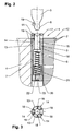
- the device 1 shown in the figures for holding stacked sheets 2, in particular transformer sheets, the from a supply roll (not shown) continuously unrolled, then cut to length and shape are and each have at least one thread hole 3 is in Used installations in which the sheets 2 in the conveying direction to be stacked on pallets 4 cutting. It is above the sheets, i. above a feeder (not shown) in which the sheets are magnetic or by means of are held by a vacuum, at least one threading bolt. 5 provided in the thread hole 3 in the respective sheet 2 and then with the same in the direction of the pallet 4 movable is trained.
- the device 1 consists of at least one Guide cartridge 6, the first in a hole 7 of the respective Pallet 4 is used.
- the guide cartridge 6 engages the Threaded bolt 5 in its downward movement with its lower End provided threading tip 8 (see Fig. 4a and 4b).
- the threading pin 5 moves the guide cartridge 6 in the Hole 7 of the pallet 4 or already stacked sheets. 2 in the coaxial Mahdellöchern 3 down.
- the same time Wegbegrenzer for the threading bolt 3 is to be stacked on the Sheet 2 (see Fig. 4c).
- the guide cartridge 6 automatically decoupled.
- the guide cartridge 6 slides after decoupling in the Bore 7 or in the Kladellöchern 3 so far back down, that the upper edge 11 of the guide cartridge 6 on the top 12th the last stacked sheet 2 protrudes.
- the Guide cartridge 6 at its upper end three in radial Bores 13 movable locking balls 14 in the rest position of one in a coaxial bore 15th movable pin 16 are held in its outer position, wherein the locking balls 14 on the outer circumference 17 of Guide cartridge 6 survive and shoulders 18 at the end of Holes 13 are held (see Figures 1, 2, 4a, 4b, 4e and 4f).
- Thread tip 8 am front end formed spherical, causing the Arretierkugeln 14 behind the spherical portion 19 of Thread tip 8 can intervene.
- a Screwed 20 screwed in which a compression spring 21st supported, the pin 16 when moving out of the threading bolt. 5 pushes back to its upper rest position and stops there.
- the Pin 16 is connected to a remote portion 22 in one coaxial bore 23 of the screw 20, with the Preload can be adjusted, guided.
- the scraper 10th from several sections, which are each radially movable, wherein the sections are supported against each other inside and after are biased externally by compression spring 24.
- the center hole 25 the scraper 10 is preferably conical, so that the threading bolt 5 easier to penetrate into the central bore 25 can and the sections are forced apart.
Landscapes
- Engineering & Computer Science (AREA)
- Power Engineering (AREA)
- Mechanical Engineering (AREA)
- Manufacturing & Machinery (AREA)
- Sheets, Magazines, And Separation Thereof (AREA)
- Stackable Containers (AREA)
Abstract
Description
- Fig. 1
- einen Längsschnitt einer erfindungsgemäßen Vorrichtung, wobei eine Hälfte mit einer Palette und die andere Hälfte mit bereits gestapelten Blechen dargestellt ist,
- Fig. 2
- einen vergrößerten Ausschnitt II aus Fig. 1,
- Fig. 3
- einen vergrößerten Schnitt nach der Linie III-III in Fig. 1 und die
- Fign. 4a-4f
- in Längsschnittdarstellung die einzelnen Schritte beim Abstapeln eines Bleches.
Claims (7)
- Vorrichtung zum Halten von abgestapelten Blechen, insbesondere Transformatorblechen, die von einer Vorratsrolle kontinuierlich abgerollt werden, nachfolgend auf Länge und Form geschnitten sind und jeweils mindestens ein Fädelloch aufweisen, wobei die Bleche in Förderrichtung nach dem Schneiden auf Paletten abgestapelt werden und oberhalb der Bleche mindestens ein Fädelbolzen vorgesehen ist, der in das Fädelloch in dem jeweiligen Blech und anschließend mit demselben in Richtung der Palette bewegbar ausgebildet ist, dadurch gekennzeichnet, daß mindestens eine Führungspatrone (6) vor Beginn des Abstapelns in eine Bohrung (7) der jeweiligen Palette (4) eingesetzt ist, in die der Fädelbolzen (5) bei der Abwärtsbewegung desselben mit seiner am unteren Ende vorgesehenen Fädelspitze (8) eingreift, wobei der Fädelbolzen (5) die Führungspatrone (6) in der Bohrung (7) der Palette (4) bzw. in den Fädellöchern (3) bereits abgestapelter Bleche (2) nach unten bewegt und der Fädelbolzen (5) bei der Aufwärtsbewegung die Führungspatrone (6) automatisch entkoppelt wird, wenn die Oberkante (11) der Führungspatrone (6) über die Oberseite (12) des zuletzt abgestapelten Bleches (2) übersteht.
- Vorrichtung nach Anspruch 1, dadurch gekennzeichnet, daß die Führungspatrone (6) an ihrem oberen Ende drei in radialen Bohrungen (13) bewegbare Arretierkugeln (14) aufweist, die in Ruhestellung von einem in einer koaxialen Bohrung (15) bewegbaren Stift (16) in ihrer äußeren Lage gehalten werden, wobei die Arretierkugeln (14) über den äußeren Umfang (17) der Führungspatrone (6) überstehen und an Schultern (18) am Ende der Bohrungen (13) gehalten sind.
- Vorrichtung nach Anspruch 1 oder 2, dadurch gekennzeichnet, daß am unteren Ende der Führungspatrone (6) ein Einschraubstück (20) eingeschraubt ist, an dem sich eine Druckfeder (21) abstützt, die den Stift (16) in Ruhestellung in seiner oberen Lage hält, wobei der Stift (16) mit einem abgesetzten Teilstück (22) in einer Bohrung (23) des Einschraubstückes (20) geführt ist.
- Vorrichtung nach einem der Ansprüche 1 bis 3, dadurch gekennzeichnet, daß die Fädelspitze (8) am vorderen Ende kugelförmig ausgebildet ist und die Arretierkugeln (14) hinter den kugelförmigen Abschnitt (19) der Fädelspitze (8) beim Eintauchen derselben in die Bohrung (15) des Stiftes (16) eingreifen.
- Vorrichtung nach einem der Ansprüche 1 bis 4, dadurch gekennzeichnet, daß der Fädelbolzen (5) koaxial in einem aufund abwärts bewegbaren Niederhalter (9) gelagert ist.
- Vorrichtung nach einem der Ansprüche 1 bis 5, dadurch gekennzeichnet, daß in dem Niederhalter (9) ein Abstreifer (10) vorgesehen ist, an dem die Führungspatrone (6) bei der Aufwärtsbewegung des Fädelbolzens (5) anschlägt und den Fädelbolzen (5) und die Führungspatrone (6) entkoppelt.
- Vorrichtung nach Anspruch 6, dadurch gekennzeichnet, daß der Abstreifer (10) aus mehreren Teilstücken besteht, die jeweils radial unter Federkraft bewegbar sind.
Applications Claiming Priority (2)
| Application Number | Priority Date | Filing Date | Title |
|---|---|---|---|
| DE2003132018 DE10332018B3 (de) | 2003-07-15 | 2003-07-15 | Vorrichtung zum Halten von abgestapelten Blechen, insbesondere Transformatorblechen |
| DE10332018 | 2003-07-15 |
Publications (2)
| Publication Number | Publication Date |
|---|---|
| EP1498918A1 true EP1498918A1 (de) | 2005-01-19 |
| EP1498918B1 EP1498918B1 (de) | 2008-10-29 |
Family
ID=33461935
Family Applications (1)
| Application Number | Title | Priority Date | Filing Date |
|---|---|---|---|
| EP20040016053 Expired - Lifetime EP1498918B1 (de) | 2003-07-15 | 2004-07-08 | Verfahren zum Halten von abgestapelten Blechen, insbesondere Transformatorblechen |
Country Status (3)
| Country | Link |
|---|---|
| EP (1) | EP1498918B1 (de) |
| JP (1) | JP4315870B2 (de) |
| DE (2) | DE10332018B3 (de) |
Cited By (1)
| Publication number | Priority date | Publication date | Assignee | Title |
|---|---|---|---|---|
| EP3739604A1 (de) | 2019-05-15 | 2020-11-18 | Heinrich Georg GmbH Maschinenfabrik | Verfahren zum automatischen stapeln von plattenförmigem steapelgut, insbesondere transformatorenkernblechen |
Families Citing this family (2)
| Publication number | Priority date | Publication date | Assignee | Title |
|---|---|---|---|---|
| DE102010061022B3 (de) | 2010-12-03 | 2012-03-01 | Wilhelm Hedrich Vakuumanlagen Gmbh & Co. Kg | Verfahren und Vorrichtung zum Herstellen eines Stapels von Blechen |
| WO2019030349A1 (de) * | 2017-08-10 | 2019-02-14 | Heinrich Georg Gmbh Maschinenfabrik | Vorrichtung und verfahren zur herstellung von transformatorkernen |
Citations (3)
| Publication number | Priority date | Publication date | Assignee | Title |
|---|---|---|---|---|
| JPS58207220A (ja) * | 1982-05-25 | 1983-12-02 | Ricoh Co Ltd | ワ−ク供給装置 |
| JPS62191366A (ja) * | 1986-02-18 | 1987-08-21 | Toshiba Corp | 鋼板の積層装置 |
| DE4338981A1 (de) * | 1992-11-16 | 1994-06-16 | Fuji Electric Co Ltd | Einrichtung zum Schichten von Platten |
Family Cites Families (1)
| Publication number | Priority date | Publication date | Assignee | Title |
|---|---|---|---|---|
| DE3816266A1 (de) * | 1988-05-12 | 1989-11-23 | Schoen & Cie Gmbh | Aufnahme- und stapelvorrichtung fuer aus einer materialbahn aus gestanzten scheiben mit mittelloch |
-
2003
- 2003-07-15 DE DE2003132018 patent/DE10332018B3/de not_active Expired - Fee Related
-
2004
- 2004-07-08 EP EP20040016053 patent/EP1498918B1/de not_active Expired - Lifetime
- 2004-07-08 DE DE200450008335 patent/DE502004008335D1/de not_active Expired - Lifetime
- 2004-07-14 JP JP2004206720A patent/JP4315870B2/ja not_active Expired - Fee Related
Patent Citations (3)
| Publication number | Priority date | Publication date | Assignee | Title |
|---|---|---|---|---|
| JPS58207220A (ja) * | 1982-05-25 | 1983-12-02 | Ricoh Co Ltd | ワ−ク供給装置 |
| JPS62191366A (ja) * | 1986-02-18 | 1987-08-21 | Toshiba Corp | 鋼板の積層装置 |
| DE4338981A1 (de) * | 1992-11-16 | 1994-06-16 | Fuji Electric Co Ltd | Einrichtung zum Schichten von Platten |
Non-Patent Citations (2)
| Title |
|---|
| PATENT ABSTRACTS OF JAPAN vol. 0080, no. 54 (M - 282) 10 March 1984 (1984-03-10) * |
| PATENT ABSTRACTS OF JAPAN vol. 0120, no. 39 (M - 665) 5 February 1988 (1988-02-05) * |
Cited By (1)
| Publication number | Priority date | Publication date | Assignee | Title |
|---|---|---|---|---|
| EP3739604A1 (de) | 2019-05-15 | 2020-11-18 | Heinrich Georg GmbH Maschinenfabrik | Verfahren zum automatischen stapeln von plattenförmigem steapelgut, insbesondere transformatorenkernblechen |
Also Published As
| Publication number | Publication date |
|---|---|
| DE10332018B3 (de) | 2005-01-13 |
| EP1498918B1 (de) | 2008-10-29 |
| DE502004008335D1 (de) | 2008-12-11 |
| JP2005041693A (ja) | 2005-02-17 |
| JP4315870B2 (ja) | 2009-08-19 |
Similar Documents
| Publication | Publication Date | Title |
|---|---|---|
| DE102013106375B4 (de) | Vorrichtung und Verfahren zum Einsetzen eines Rondenkerns in einen Rondenring | |
| DE4338981C2 (de) | Einrichtung zum Schichten von Platten | |
| DE3220461A1 (de) | Vorrichtung zum einbringen von loechern in dicke papierstapel | |
| DE102020125148A1 (de) | Kombiniertes Feuerwerk und sein Herstellungsverfahren | |
| DE102010061022B3 (de) | Verfahren und Vorrichtung zum Herstellen eines Stapels von Blechen | |
| DE102017003503A1 (de) | Verfahren zur Herstellung von Stapeln aus Bögen | |
| DE2133720C3 (de) | Vorrichtung zum Zusammenbauen eines Radialrollenlagers | |
| DE202017004863U1 (de) | Anlage zum Lagern und Transportieren von Paletten | |
| DE69107494T2 (de) | Vorrichtung zum Trennen der Bleche in einer Maschine zum Bearbeiten von Plattenblattelementen zum Herstellen von Verpackungen. | |
| DE10332018B3 (de) | Vorrichtung zum Halten von abgestapelten Blechen, insbesondere Transformatorblechen | |
| EP2062838B1 (de) | Verfahren und Vorrichtung zur Entfernung von Zwischenablagen von palettierten Waren und Gütern | |
| DE102014105930A1 (de) | Schiebevorrichtung für eine Palettiervorrichtung | |
| DE4408100B4 (de) | Vorrichtung für das Pressblechspannen in einer Heißpresse | |
| DE2009138C3 (de) | Einrichtung zum kontinuierlichen Abtransport von Werkstücken | |
| DE3541623C1 (de) | Magazin für Stapel von Blechteilen, insbesondere für die Herstellung von Dosen | |
| DE202020101249U1 (de) | Zerlegergeschoss | |
| DE202015104275U1 (de) | Umreifungsvorrichtung für Packstücke | |
| DE102007050498B4 (de) | Verfahren zur Herstellung von Schlitzen in der Bodenwand einer napfförmigen Hülsenanordnung | |
| CH473043A (de) | Verfahren zum Stapeln von kontinuierlich aufeinanderfolgend transportierten Drucklagen und Vorrichtung zu seiner Durchführung | |
| EP2322456A2 (de) | Stapelungsvorrichtung zum Stapeln von Dokumenten | |
| DE102018000987A1 (de) | Setzgerät | |
| DE3143912A1 (de) | Entstifteinrichtung | |
| DE1602574C (de) | Stapelvorrichtung an einer Nutenstanze | |
| DE3400981A1 (de) | Vorrichtung zum schichten von eisenkernen aus einzelblechen | |
| DE8032616U1 (de) | Vorrichtung zum montieren von bolzen |
Legal Events
| Date | Code | Title | Description |
|---|---|---|---|
| PUAI | Public reference made under article 153(3) epc to a published international application that has entered the european phase |
Free format text: ORIGINAL CODE: 0009012 |
|
| AK | Designated contracting states |
Kind code of ref document: A1 Designated state(s): AT BE BG CH CY CZ DE DK EE ES FI FR GB GR HU IE IT LI LU MC NL PL PT RO SE SI SK TR |
|
| AX | Request for extension of the european patent |
Extension state: AL HR LT LV MK |
|
| 17P | Request for examination filed |
Effective date: 20050426 |
|
| AKX | Designation fees paid |
Designated state(s): BE CH DE IT LI |
|
| 17Q | First examination report despatched |
Effective date: 20071019 |
|
| GRAP | Despatch of communication of intention to grant a patent |
Free format text: ORIGINAL CODE: EPIDOSNIGR1 |
|
| GRAS | Grant fee paid |
Free format text: ORIGINAL CODE: EPIDOSNIGR3 |
|
| GRAA | (expected) grant |
Free format text: ORIGINAL CODE: 0009210 |
|
| RTI1 | Title (correction) |
Free format text: METHOD FOR RETAINING STACKED SHEETS, IN PARTICULAR TRANSFORMER SHEETS |
|
| AK | Designated contracting states |
Kind code of ref document: B1 Designated state(s): BE CH DE IT LI |
|
| REG | Reference to a national code |
Ref country code: CH Ref legal event code: EP Ref country code: CH Ref legal event code: NV Representative=s name: ALDO ROEMPLER PATENTANWALT |
|
| REF | Corresponds to: |
Ref document number: 502004008335 Country of ref document: DE Date of ref document: 20081211 Kind code of ref document: P |
|
| PLBE | No opposition filed within time limit |
Free format text: ORIGINAL CODE: 0009261 |
|
| STAA | Information on the status of an ep patent application or granted ep patent |
Free format text: STATUS: NO OPPOSITION FILED WITHIN TIME LIMIT |
|
| 26N | No opposition filed |
Effective date: 20090730 |
|
| PGFP | Annual fee paid to national office [announced via postgrant information from national office to epo] |
Ref country code: IT Payment date: 20190723 Year of fee payment: 16 Ref country code: DE Payment date: 20190923 Year of fee payment: 16 |
|
| PGFP | Annual fee paid to national office [announced via postgrant information from national office to epo] |
Ref country code: BE Payment date: 20190722 Year of fee payment: 16 |
|
| PGFP | Annual fee paid to national office [announced via postgrant information from national office to epo] |
Ref country code: CH Payment date: 20190725 Year of fee payment: 16 |
|
| REG | Reference to a national code |
Ref country code: DE Ref legal event code: R119 Ref document number: 502004008335 Country of ref document: DE |
|
| REG | Reference to a national code |
Ref country code: CH Ref legal event code: PL |
|
| REG | Reference to a national code |
Ref country code: BE Ref legal event code: MM Effective date: 20200731 |
|
| PG25 | Lapsed in a contracting state [announced via postgrant information from national office to epo] |
Ref country code: CH Free format text: LAPSE BECAUSE OF NON-PAYMENT OF DUE FEES Effective date: 20200731 Ref country code: LI Free format text: LAPSE BECAUSE OF NON-PAYMENT OF DUE FEES Effective date: 20200731 |
|
| PG25 | Lapsed in a contracting state [announced via postgrant information from national office to epo] |
Ref country code: DE Free format text: LAPSE BECAUSE OF NON-PAYMENT OF DUE FEES Effective date: 20210202 Ref country code: BE Free format text: LAPSE BECAUSE OF NON-PAYMENT OF DUE FEES Effective date: 20200731 |
|
| PG25 | Lapsed in a contracting state [announced via postgrant information from national office to epo] |
Ref country code: IT Free format text: LAPSE BECAUSE OF NON-PAYMENT OF DUE FEES Effective date: 20200708 |