EP1498788A1 - Dispositif d'affichage pour montre - Google Patents
Dispositif d'affichage pour montre Download PDFInfo
- Publication number
- EP1498788A1 EP1498788A1 EP03405532A EP03405532A EP1498788A1 EP 1498788 A1 EP1498788 A1 EP 1498788A1 EP 03405532 A EP03405532 A EP 03405532A EP 03405532 A EP03405532 A EP 03405532A EP 1498788 A1 EP1498788 A1 EP 1498788A1
- Authority
- EP
- European Patent Office
- Prior art keywords
- display
- gear
- train
- wheel
- disc
- Prior art date
- Legal status (The legal status is an assumption and is not a legal conclusion. Google has not performed a legal analysis and makes no representation as to the accuracy of the status listed.)
- Withdrawn
Links
- 230000007246 mechanism Effects 0.000 claims abstract description 33
- 230000033001 locomotion Effects 0.000 claims abstract description 29
- 238000005259 measurement Methods 0.000 claims description 10
- 230000001276 controlling effect Effects 0.000 claims description 5
- 210000000056 organ Anatomy 0.000 claims description 2
- 230000001105 regulatory effect Effects 0.000 claims description 2
- 238000012549 training Methods 0.000 description 15
- 238000004804 winding Methods 0.000 description 13
- 230000000694 effects Effects 0.000 description 6
- 230000000717 retained effect Effects 0.000 description 3
- 230000000295 complement effect Effects 0.000 description 2
- 239000010453 quartz Substances 0.000 description 2
- VYPSYNLAJGMNEJ-UHFFFAOYSA-N silicon dioxide Inorganic materials O=[Si]=O VYPSYNLAJGMNEJ-UHFFFAOYSA-N 0.000 description 2
- 108091028072 EteRNA Proteins 0.000 description 1
- 230000003042 antagnostic effect Effects 0.000 description 1
- 238000012550 audit Methods 0.000 description 1
- 230000000903 blocking effect Effects 0.000 description 1
- 239000000470 constituent Substances 0.000 description 1
- 230000000994 depressogenic effect Effects 0.000 description 1
- 239000002184 metal Substances 0.000 description 1
- 235000020004 porter Nutrition 0.000 description 1
- 230000035945 sensitivity Effects 0.000 description 1
- 230000035939 shock Effects 0.000 description 1
- 239000003381 stabilizer Substances 0.000 description 1
Images


Classifications
-
- G—PHYSICS
- G04—HOROLOGY
- G04B—MECHANICALLY-DRIVEN CLOCKS OR WATCHES; MECHANICAL PARTS OF CLOCKS OR WATCHES IN GENERAL; TIME PIECES USING THE POSITION OF THE SUN, MOON OR STARS
- G04B19/00—Indicating the time by visual means
- G04B19/24—Clocks or watches with date or week-day indicators, i.e. calendar clocks or watches; Clockwork calendars
-
- G—PHYSICS
- G04—HOROLOGY
- G04B—MECHANICALLY-DRIVEN CLOCKS OR WATCHES; MECHANICAL PARTS OF CLOCKS OR WATCHES IN GENERAL; TIME PIECES USING THE POSITION OF THE SUN, MOON OR STARS
- G04B1/00—Driving mechanisms
- G04B1/10—Driving mechanisms with mainspring
- G04B1/12—Driving mechanisms with mainspring with several mainsprings
-
- G—PHYSICS
- G04—HOROLOGY
- G04B—MECHANICALLY-DRIVEN CLOCKS OR WATCHES; MECHANICAL PARTS OF CLOCKS OR WATCHES IN GENERAL; TIME PIECES USING THE POSITION OF THE SUN, MOON OR STARS
- G04B1/00—Driving mechanisms
- G04B1/10—Driving mechanisms with mainspring
- G04B1/22—Compensation of changes in the motive power of the mainspring
- G04B1/225—Compensation of changes in the motive power of the mainspring with the aid of an interposed power-accumulator (secondary spring) which is always tensioned
-
- G—PHYSICS
- G04—HOROLOGY
- G04B—MECHANICALLY-DRIVEN CLOCKS OR WATCHES; MECHANICAL PARTS OF CLOCKS OR WATCHES IN GENERAL; TIME PIECES USING THE POSITION OF THE SUN, MOON OR STARS
- G04B19/00—Indicating the time by visual means
- G04B19/20—Indicating by numbered bands, drums, discs, or sheets
- G04B19/202—Indicating by numbered bands, drums, discs, or sheets by means of turning discs
-
- G—PHYSICS
- G04—HOROLOGY
- G04F—TIME-INTERVAL MEASURING
- G04F7/00—Apparatus for measuring unknown time intervals by non-electric means
- G04F7/04—Apparatus for measuring unknown time intervals by non-electric means using a mechanical oscillator
- G04F7/08—Watches or clocks with stop devices, e.g. chronograph
- G04F7/0804—Watches or clocks with stop devices, e.g. chronograph with reset mechanisms
-
- G—PHYSICS
- G04—HOROLOGY
- G04F—TIME-INTERVAL MEASURING
- G04F7/00—Apparatus for measuring unknown time intervals by non-electric means
- G04F7/04—Apparatus for measuring unknown time intervals by non-electric means using a mechanical oscillator
- G04F7/08—Watches or clocks with stop devices, e.g. chronograph
- G04F7/0842—Watches or clocks with stop devices, e.g. chronograph with start-stop control mechanisms
-
- G—PHYSICS
- G04—HOROLOGY
- G04F—TIME-INTERVAL MEASURING
- G04F7/00—Apparatus for measuring unknown time intervals by non-electric means
- G04F7/04—Apparatus for measuring unknown time intervals by non-electric means using a mechanical oscillator
- G04F7/08—Watches or clocks with stop devices, e.g. chronograph
- G04F7/0866—Special arrangements
- G04F7/089—Special arrangements indicating measured time by other than hands, e.g. numbered bands, drums, discs or sheet
-
- G—PHYSICS
- G04—HOROLOGY
- G04F—TIME-INTERVAL MEASURING
- G04F7/00—Apparatus for measuring unknown time intervals by non-electric means
- G04F7/04—Apparatus for measuring unknown time intervals by non-electric means using a mechanical oscillator
- G04F7/08—Watches or clocks with stop devices, e.g. chronograph
- G04F7/0866—Special arrangements
- G04F7/0895—Special arrangements with a separate barrel for the chronograph functions
Definitions
- a disk is understood to mean a round piece, generally made of plastic or metal, which can be pierced or not in its center and carries indications to display.
- Display of information by means of one or more disks is known of the skilled person.
- One of the most frequent applications concerns indication of the day and date, the display being done by means of two discs, which make a jump a day.
- the movement is usually provided with a spring, armed by the gear of finishing, which relaxes around midnight, thus making the day and the day the following indication. It can also be driven at first in a slow motion ensured by the cogwheel of the watch, then by a jump generated by a jumper.
- the purpose of the present invention is to ensure optimal training of the discs, even of great size and without affecting the good running of the watch.
- the second source of energy is mechanical, at like a barrel.
- the device according to the invention furthermore comprises means of arming this source of energy.
- the device comprises drive means driven by the wheel of chronograph and commanding drive the display gear by the barrel.
- the display gear is arranged in such a way that the disc ensures the display of timed times greater than or equal to the minute.
- Such a device may include several display disks and several barrels, each barrel driving a disc.
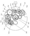
- the watch shown in FIG. 1 comprises a box 10 defining a housing within which is a movement.
- the latter is equipped of a chronograph mechanism, well known in itself, as well as a device display according to the invention which will be described in more detail below.
- Dial 12 has three wickets through of which discs 24, 26 and 28 appear, respectively displaying the hours, tens of minutes and minutes units of time timed, thus ensuring the display function of the device according to the invention.
- a winding crown and time setting 30 and pushers 31 and 32 are arranged in a conventional manner, on the edge of the box 10.
- the crown 30 provides the necessary mechanical energy to the operation of the movement, by winding a mainspring, as will be explained later.
- the pushers 31 and 32 control respectively the start and stop, and the zeroing of the chronograph and its display device.
- the base of the movement consists of a chronograph caliber such as marketed by ETA SA (Switzerland) under the reference 7750.
- This movement comprises a plate 33, visible in FIG. chronograph and a start and stop mechanism, which are only very partially visible in the drawing, being well known to those skilled in the art.
- he comprises, in addition, a barrel, a finishing gear, an exhaust and a pendulum.
- the barrel brings energy to the wheel of finishing, which delivers it to the exhaust, which transforms the movement rotary of the gear in reciprocating motion, to power the balance.
- the chronograph wheel includes a seconds wheel of time timed, which carries the seconds hand of time timed 22, and a wheel of minutes of time timed 34 driven so classic by the seconds wheel of timed time, at a rate of not every minute.
- the minute wheel 34 carries the minute hand of time timed.
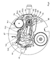
- the display device comprises, on the plate 33, drive means 36 of the disk of the units 28, more particularly illustrated in FIG. 2.
- These training means 36 comprise a trigger mechanism 38 controlled by the wheel 34, a system of regulation 40 released by the trigger mechanism 38, a cog driving the display 42 of the disk of the units 28 and a source of energy formed of a cylinder 43 supplying its energy both to the system 40 and the gearbox 42.
- the trigger mechanism 38 is formed of two levers 44 and 46 pivotally mounted on the plate 33 and a spring 48.
- the lever 44 has two arms 44a and 44b disposed on either side of its pivot point, the arm 44a being provided, at its free end, with a finger 44c arranged to be in engagement with the toothing of the wheel 34.
- the lever 46 is provided with two lifts 46a and 46b intended to cooperate with the control system 40, as will be explained later, and a pad 46c cooperating with the lever 44. It is kept in the rest position, the lifts 46a and 46b retaining the regulation system 40, under the effect of the spring 48.
- the levers 44 and 46 are arranged and cooperate with each other so such as when the wheel 34 raises the lever 44, the arm 44b applies against the stud 46c a force antagonistic to that of the spring 48. This rotates the lever 46, which causes the release of the lifts 46a and 46b of the system of regulation 40.
- the regulation system 40 comprises a multiplier gear train of the speed comprising two mobiles 50 and 52, and a flywheel 54.
- mobile 50 comprises a pinion 50a, which meshes with the barrel 43, and a 50b wheel driving the mobile 52 by its pinion not visible in the drawing.
- This mobile carries a wheel 52b and a cam 52c.
- the wheel 52b meshes with a pinion not visible in the drawing that includes the steering wheel 54.
- the cam 52c is present in the form of a washer provided with a notch 52d. She cooperates with the lift 46a of the lever 46, which is held by the spring 48 in support against the periphery of the cam or engaged in the notch 52d, according to the position of the mobile 52.
- the steering wheel 54 is provided with two arms 54a each carrying a wing 54b, as well as three retaining fingers 54c, arranged radially and arranged to cooperate with lifting 46b.
- the wings 54b each comprise an elastic portion 54d in an arc of a circle concentric with the axis of rotation of the steering wheel, integral with one of the arms 54a by one of its ends, and extending on an angle about 90 °.
- the elastic portions 54d are provided, at their other end, a mass of inertia and braking 54e, intended to cooperate with a drum 56 surrounding the wheel 54 and secured to the plate 33. More precisely, when the wheel 54 turns, the elastic portions 54d of the wings 54b deform elastically under the effect of their mass of inertia 54e, which come rub against the drum 56.
- the drive train of the display 42 comprises a mobile 58, in mesh with the toothing of the cylinder 43 by its pinion, a reference 60, driven by the mobile wheel 58, and driving a wheel 62 units. This last door the disk of the units 28, as well as a trigger cam 64, which is provided with a pin 64a and a finger 64b, whose functions will be specified below.
- the mobiles of the regulation system 40 and the gear train 42 are numbered of so that the wheel 62 rotates 36 ° for a turn of the mobile 52.
- the drive train 42 rotates and moves the wheel 62 forward. of 36 ° and with it the disc of the units 28 of a step, the visible display at the through the window being incremented by one unit.
- Such a structure makes it possible to explain in a simple manner the principle of operation of the device, the functions of regulation and training being separated. It would also be possible to simplify the structure by combining these functions, by meshing the pinion of the mobile 52 with a wheel that would carry the mobile 58, the reference 60 or the wheel 62.
- FIG. 3 represents means of training 136 of the disc of 26. They are, for the most part, similar to the means of training 36 of the units disk, the constituent parts bearing the same reference than those of the training means 36, equipped with a "1" for the number of hundreds.
- the operation of the drive means 136 is, of course, also comparable to that of training facilities 36.
- the cam 64 As soon as the cam 64 has finished moving, it releases the levers 144 and 146, so that the spring 148 causes the lift 146a to bear against the cam 152c. When the latter has completed a complete turn, the lift 146a falls into the notch 152d of the cam 152 and blocks its movement. The tens disk 26 so jumped a step.
- the mobiles of the drive train 142 and the regulation system 140 are numbered so that the tens disk 26 turns from 60 ° to every step, this disc bearing the numbers from 0 to 5.
- the wheel 162 is furthermore provided with a cam 164, comprising a pin 164a and a finger 164b arranged to control the jump of the hour disk 24, as will be explained later.
- the drive of the 24 hours drive is done by means 236, illustrated in Figure 4 and similar to the means 36 and 136, the component parts bearing the same reference than those of the training means 36 and 136, provided with a "2" for number of hundreds.
- the operation of the drive means 236 is, of course, also comparable to that of training facilities 36. In this case, however, the number of mobiles that comprise the regulation system 240 and the gear train 242 drive is higher. This does not change his operation.
- the train of training 242 comprises a mobile 260 arranged concentrically with the wheels 62 and 162, and provided with a pin 260a whose function will be specified later.
- the wheel 262 which carries the disc 24, is in the form of a ring surrounding the center of the movement in an off-center manner, and place by means of a plate 263, fixed to the plate 33 by means of screws represented in the drawing, and pierced with a hole through which the axis of the seconds wheel of timed time as well as the mobiles bearing the hour 14 and minute hands 16.
- the drive means 36, 136 and 236, the drive of the disks 24, 26 and 28 is done without increasing the load of the cylinder ensuring rotation the finishing gear.
- the amplitude of the pendulum is not affected by the jumps of the display disks.
- FIGS 5a and 5b show the opposite faces of a winding mechanism 65 of the barrel springs that includes the movement.
- a winding mechanism 65 of the barrel springs that includes the movement.
- it also raises the barrel 66 for driving the gear train and mentioned above.
- These barrels each comprise a drum identified by the letter a, a shaft b, not shown in the drawing and spring having one end attached to the shaft b, and the other cooperating with the inner wall of the drum by means of a slippery flange.
- a ratchet wheel, identified by the letter c is attached to the shaft b.
- barrels 143 and 243 are coaxial. Their trees 143b and 243b are arranged to be solidary in rotation, and driven together by the wheel to Ratchet 143c.
- FIGS. 1-10 show the crown of winding and setting time 30. It is secured to a rod 67 ensuring the connection between the outside and the inside of the box 10.
- a winding pinion 68 and a gear pinion hour 70 are mounted pivoting on the rod 67, kinematically connected one to the other by a Breguet toothing, and cooperating with a mechanism of winding and setting time, as is customary in this type of movements, but that was not represented to avoid overloading the drawing.
- a crown wheel 72 rotatably mounted on a bridge, not shown drawing, meshes with the winding pinion 68 as well as with the wheel Ratchet 66c of the barrel 66, visible in Figure 5b.
- a train of referrals 74 interconnects the ratchet wheels. More precisely, a first reference 74a is mounted on a square 66d that includes the shaft 66b. he causes a second referral 74b engaged with the ratchet wheel 43c. This last is connected to the ratchet wheel 143c, visible in Figure 5b, by four references 74c to 74f.
- the number of referrals (even or odd) between two ratchet wheels is function of the direction of rotation in which the spring is wound.
- the four barrels 66, 43 are armed, 143 and 243. They can, without further, be fully armed, whatever their state initial, because they are all equipped with a sliding flange.
- the device thus described makes it possible to drive each of the disks of the display of the chronograph by means of a barrel of its own. In this way, it is not taken from the finishing gear, that the energy required for the training wheels of seconds and minutes of time timed and at triggering the device.
- the 24-hour disc performs nine steps and one turn at maximum, it is also possible to store the energy needed for its drive otherwise than in a cylinder, for example in a spring cooperating with a spiral.
- the display device further comprises a mechanism zeroing of the disks 24, 26 and 28, partially illustrated on the Figure 6. It is controlled by the pushers 31 and 32 shown in the figure 1. It cooperates with a control lever 76, part of the mechanism of chronograph, activated by the pusher 31 and which actuates a connecting clutch, in a conventional manner, the finishing gear wheel 34, via a chronograph seconds wheel, not shown in the drawing.
- a first pressure on the pusher 31 starts the measurement and engages the clutch.
- a second press stops the measurement by declutching.
- the records can be set to zero by pressing the pushbutton 32, which control of the means of zeroing that includes the mechanism of chronograph.
- These means comprise, in a conventional manner, a lever of zeroing 78 which actuates a hammer ensuring the zeroing of the wheel chronograph seconds.
- the hooks 84b are arranged in such a way that that they cooperate with the pins 64a, 164a and 260a, to define the position initial discs 24, 26 and 28, as will be explained later.
- the lever command 76 rotates the latch 82 which drives the body of positioning 84 via the fingers 84a, to the position represented in FIG. 6.
- the latch 82 is maintained in its new position by the jumper 90. In this way, the positioning hooks 84b away from the pins. Discs 24, 26 and 28 are no longer retained and can not be rotated, which is what the wheel 34 each of his turns for the disk 28, the other disks being incremented as indicated above.
- a new pressure on the pusher 31 has the effect of moving the clutch, so that the chronograph gear is no longer engaged with the finishing gear train Thus, the measurement is interrupted, the display of the timed time being fixed. The information can therefore be read. It will be noted that this new pressure does not act on organ 84, since is held in the depressed position by the jumper 90.
- the flip-flop 86 raises the levers 44, 144 and 244, the last two by through the lever 87.
- the levers 44, 144 and 244 operate respectively the levers 46, 146 and 246, so that the lifts they comprise release control systems 40, 140 and 240, respectively visible in FIGS. 2, 3 and 4. Consequently, the drive trainings 42, 142 and 242 can rotate under the effect of springs that include barrels 43, 143 and 243.
- the flip-flop 82 causes, via one of the fingers 84a, the positioning member 84, so that the hooks 84b again find on the way pins 64a, 164a and 260a.
- the end of the flip-flop 82 next to the lever 86 engages in a notch that includes last, masked by the wheel 62, so that they remain engaged one with the other, now furthermore the positioning member 84 in the position of blocking disks.
- the pins 64a, 164a and 260a are, of course, arranged in such a way that they cooperate with hooks 84b and that they stop the discs in a position such that the numbers "0" appear in the windows.
- the levers 44, 46, 144, 146, 244 and 246 have cutouts that allow them to be balanced and alleviate. In this way, the forces to be applied to operate the mechanism, and sensitivity to shocks are greatly reduced.
- the display device described above is associated with a mechanism of chronograph.
- the same device could easily be applied to a countdown mechanism, for example, of the type displaying a time descending, or intended at the start of regattas.
- the winding of the barrels is done in one operation. It is also imaginable to provide the movement of a second winding crown, the barrel driving the finishing gear and those resulting in the display of the timed time being armed independently, one by the crown arranged at 3 o'clock, the others by a crown which can be find at 9 o'clock for example. It is also possible to imagine a quartz watch equipped with a chronograph mechanism for example, the energy source of the watch being a battery, while the training of discs would be by means of mechanical energy sources.
- the energy supplied to the display device does not come from the mainspring or the motor providing the drive of the finishing gear.
- the means ensuring the connection between the barrel or barrels and the display disc (s) may have numerous variants, depending on the purpose and the fantasy of the manufacturer.
- the watch as described is advantageously equipped with an indicator of a power reserve, for example that described in the EP application filed on same day as this one on behalf of ETERNA SA, which allows an indication of the time during which the watch can function normally, taking into account counts both the barrel of the basic movement and that of the units.
- the device described above is directly mounted on the plate of the movement. It would also be possible to realize this device on a complementary stage, thus forming a module to fix on the movement of based.
Landscapes
- Physics & Mathematics (AREA)
- General Physics & Mathematics (AREA)
- Measurement Of Unknown Time Intervals (AREA)
- Electromechanical Clocks (AREA)
- Electric Clocks (AREA)
Priority Applications (8)
| Application Number | Priority Date | Filing Date | Title |
|---|---|---|---|
| EP03405532A EP1498788A1 (fr) | 2003-07-14 | 2003-07-14 | Dispositif d'affichage pour montre |
| AT04738074T ATE480801T1 (de) | 2003-07-14 | 2004-07-08 | Display-einrichtung für eine uhr |
| US10/564,548 US7508738B2 (en) | 2003-07-14 | 2004-07-08 | Display device for a watch |
| CNB2004800200322A CN100557526C (zh) | 2003-07-14 | 2004-07-08 | 手表用显示装置 |
| DE602004029059T DE602004029059D1 (de) | 2003-07-14 | 2004-07-08 | Display-einrichtung für eine uhr |
| EP04738074A EP1658531B1 (fr) | 2003-07-14 | 2004-07-08 | Dispositif d affichage pour montre |
| JP2006519740A JP4759515B2 (ja) | 2003-07-14 | 2004-07-08 | 腕時計用表示装置 |
| PCT/CH2004/000433 WO2005006087A1 (fr) | 2003-07-14 | 2004-07-08 | Dispositif d'affichage pour montre |
Applications Claiming Priority (1)
| Application Number | Priority Date | Filing Date | Title |
|---|---|---|---|
| EP03405532A EP1498788A1 (fr) | 2003-07-14 | 2003-07-14 | Dispositif d'affichage pour montre |
Publications (1)
| Publication Number | Publication Date |
|---|---|
| EP1498788A1 true EP1498788A1 (fr) | 2005-01-19 |
Family
ID=33462278
Family Applications (2)
| Application Number | Title | Priority Date | Filing Date |
|---|---|---|---|
| EP03405532A Withdrawn EP1498788A1 (fr) | 2003-07-14 | 2003-07-14 | Dispositif d'affichage pour montre |
| EP04738074A Expired - Lifetime EP1658531B1 (fr) | 2003-07-14 | 2004-07-08 | Dispositif d affichage pour montre |
Family Applications After (1)
| Application Number | Title | Priority Date | Filing Date |
|---|---|---|---|
| EP04738074A Expired - Lifetime EP1658531B1 (fr) | 2003-07-14 | 2004-07-08 | Dispositif d affichage pour montre |
Country Status (7)
| Country | Link |
|---|---|
| US (1) | US7508738B2 (enExample) |
| EP (2) | EP1498788A1 (enExample) |
| JP (1) | JP4759515B2 (enExample) |
| CN (1) | CN100557526C (enExample) |
| AT (1) | ATE480801T1 (enExample) |
| DE (1) | DE602004029059D1 (enExample) |
| WO (1) | WO2005006087A1 (enExample) |
Cited By (7)
| Publication number | Priority date | Publication date | Assignee | Title |
|---|---|---|---|---|
| EP1857890A2 (fr) | 2006-03-30 | 2007-11-21 | Richemont International S.A. | Dispositif de déclenchement d'une impulsion |
| EP1962155A1 (fr) * | 2007-02-22 | 2008-08-27 | ETA SA Manufacture Horlogère Suisse | Montre chronographe |
| EP1978424A1 (fr) * | 2007-04-04 | 2008-10-08 | Montres Journe S.A. | Chronographe |
| EP2897003A3 (fr) * | 2014-01-16 | 2016-04-06 | Richemont International S.A. | Mouvement et pièce d'horlogerie mécanique comprenant un mécanisme de chronographe |
| EP3382471A1 (de) * | 2017-03-30 | 2018-10-03 | Richemont International S.A. | Uhr mit digitaler zeitanzeige |
| EP3382469A1 (de) * | 2017-03-30 | 2018-10-03 | Richemont International S.A. | Uhr mit digitaler zeitanzeige |
| US11675313B2 (en) | 2017-04-18 | 2023-06-13 | Patek Philippe Sa Geneve | Timepiece mechanism |
Families Citing this family (22)
| Publication number | Priority date | Publication date | Assignee | Title |
|---|---|---|---|---|
| EP1498789A1 (fr) | 2003-07-14 | 2005-01-19 | Eterna SA | Mécanisme indicateur de réserve de marche pour pièce d'horlogerie mécanique |
| JP2006170762A (ja) * | 2004-12-15 | 2006-06-29 | Seiko Instruments Inc | 扇形運針輪列を備えた多機能時計および扇形運針輪列装置 |
| JP4626971B2 (ja) * | 2004-12-15 | 2011-02-09 | セイコーインスツル株式会社 | 戻しばねを含む扇形運針機構を有する多機能時計および扇形運針輪列装置 |
| CH707467B1 (fr) | 2005-09-13 | 2014-07-15 | Lvmh Swiss Mft Sa | Montre avec affichage multifonctionnel. |
| DE602007010423D1 (de) * | 2007-04-04 | 2010-12-23 | Eta Sa Mft Horlogere Suisse | Zahnrad für Uhrwerk und Vorrichtung zur Korrektur eines Anzeigemechanismus für eine Uhr mit einem solchen Zahnrad |
| ATE475117T1 (de) * | 2007-04-04 | 2010-08-15 | Eta Sa Mft Horlogere Suisse | Aufzugsvorrichtung mit unidirektionale kupplung |
| AU327458S (en) * | 2009-03-06 | 2009-09-03 | Rado Uhren Ag Rado Watch Co Ltd Montres Rado Sa | Watch |
| DE102009019335B4 (de) * | 2009-04-30 | 2011-01-13 | Lange Uhren Gmbh | Uhr |
| USD658518S1 (en) * | 2011-03-21 | 2012-05-01 | Lvmh Swiss Manufactures Sa | Watch |
| USD665291S1 (en) * | 2011-03-21 | 2012-08-14 | Lvmh Swiss Manufactures Sa | Watch dial |
| EP3339967B1 (fr) * | 2011-06-21 | 2025-02-12 | Rolex Sa | Pièce d'horlogerie comportant un mécanisme de correction d'au moins deux organes indicateurs |
| USD676338S1 (en) * | 2012-03-06 | 2013-02-19 | Longines Watch Co., Francillon Ltd. | Watch |
| CN102914959B (zh) * | 2012-10-12 | 2014-04-02 | 杭州手表有限公司 | 一种时间显示瞬间变换机构 |
| CH707136B1 (fr) * | 2012-10-30 | 2016-12-30 | Parmigiani Fleurier S A | Pièce d'horlogerie destinée à indiquer la réserve de marche. |
| USD734173S1 (en) * | 2012-11-30 | 2015-07-14 | Lvmh Swiss Manufactures Sa | Watch |
| USD734175S1 (en) * | 2012-11-30 | 2015-07-14 | Lvmh Swiss Manufactures Sa | Watch |
| RU2525465C1 (ru) * | 2013-06-14 | 2014-08-20 | Общество с ограниченной ответственностью "Константин Чайкин" | Устройство позиционной индикации для часов и часы с устройством позиционной индикации |
| JP1526108S (enExample) * | 2014-01-20 | 2015-06-15 | ||
| JP6558761B1 (ja) * | 2018-06-19 | 2019-08-14 | セイコーインスツル株式会社 | 脱進機、時計用ムーブメント及び時計 |
| TWD208140S (zh) * | 2019-07-22 | 2020-11-11 | 瑞士商拉克雪瑞物品國際公司 | 手錶 |
| EP3904963B1 (fr) | 2020-04-29 | 2022-10-26 | Patek Philippe SA Genève | Mouvement horloger comprenant un mecanisme auxiliaire entrainé par une source d'énergie auxiliaire |
| CN113189854B (zh) * | 2021-04-12 | 2022-02-25 | 天王电子(深圳)有限公司 | 时钟显示装置以及手表 |
Citations (4)
| Publication number | Priority date | Publication date | Assignee | Title |
|---|---|---|---|---|
| FR1522084A (fr) * | 1967-05-09 | 1968-04-19 | Siemens Ag | Appareil horaire comportant un accumulateur d'énergie mécanique |
| US3675413A (en) * | 1970-07-02 | 1972-07-11 | Schild Sa A | Watch movement having totalizers |
| EP0806712A2 (de) * | 1996-05-09 | 1997-11-12 | Fortis AG | Mechanisches Uhrwerk mit integrierter Stoppuhr (Chronographenwerk) |
| WO2002093273A1 (de) * | 2001-05-14 | 2002-11-21 | Eterna Ag Uhrenfabrik | Analoger chronograph mit digitaler anzeige |
Family Cites Families (8)
| Publication number | Priority date | Publication date | Assignee | Title |
|---|---|---|---|---|
| CH599580B5 (enExample) * | 1974-08-22 | 1978-05-31 | Longines Montres Comp D | |
| JP3081992B2 (ja) * | 1996-10-02 | 2000-08-28 | セイコーインスツルメンツ株式会社 | カレンダ付き腕時計 |
| JPH11202060A (ja) * | 1998-01-09 | 1999-07-30 | Citizen Watch Co Ltd | カレンダー付き電子時計 |
| US7070320B2 (en) * | 2001-03-21 | 2006-07-04 | Glashütter Uhrenbetrieb GmbH | Mechanism for triggering a striking work for a timepiece fitted with a timer |
| WO2002077723A1 (fr) * | 2001-03-21 | 2002-10-03 | Glashütter Uhrenbetrieb GmbH | Piece d'horlogerie comportant un mecanisme pour l'enclenchement d'une fonction horaire et l'armage simultane d'un ressort de barillet |
| DE60225779T2 (de) * | 2002-02-01 | 2009-06-18 | Tag Heuer S.A. | Vorrichtung mit Uhrwerk und Chronographenmodul |
| JP4296019B2 (ja) * | 2003-03-27 | 2009-07-15 | セイコーインスツル株式会社 | 帰零構造を有するクロノグラフ時計 |
| EP1498789A1 (fr) | 2003-07-14 | 2005-01-19 | Eterna SA | Mécanisme indicateur de réserve de marche pour pièce d'horlogerie mécanique |
-
2003
- 2003-07-14 EP EP03405532A patent/EP1498788A1/fr not_active Withdrawn
-
2004
- 2004-07-08 EP EP04738074A patent/EP1658531B1/fr not_active Expired - Lifetime
- 2004-07-08 AT AT04738074T patent/ATE480801T1/de not_active IP Right Cessation
- 2004-07-08 JP JP2006519740A patent/JP4759515B2/ja not_active Expired - Fee Related
- 2004-07-08 CN CNB2004800200322A patent/CN100557526C/zh not_active Expired - Fee Related
- 2004-07-08 US US10/564,548 patent/US7508738B2/en not_active Expired - Fee Related
- 2004-07-08 DE DE602004029059T patent/DE602004029059D1/de not_active Expired - Lifetime
- 2004-07-08 WO PCT/CH2004/000433 patent/WO2005006087A1/fr not_active Ceased
Patent Citations (4)
| Publication number | Priority date | Publication date | Assignee | Title |
|---|---|---|---|---|
| FR1522084A (fr) * | 1967-05-09 | 1968-04-19 | Siemens Ag | Appareil horaire comportant un accumulateur d'énergie mécanique |
| US3675413A (en) * | 1970-07-02 | 1972-07-11 | Schild Sa A | Watch movement having totalizers |
| EP0806712A2 (de) * | 1996-05-09 | 1997-11-12 | Fortis AG | Mechanisches Uhrwerk mit integrierter Stoppuhr (Chronographenwerk) |
| WO2002093273A1 (de) * | 2001-05-14 | 2002-11-21 | Eterna Ag Uhrenfabrik | Analoger chronograph mit digitaler anzeige |
Cited By (15)
| Publication number | Priority date | Publication date | Assignee | Title |
|---|---|---|---|---|
| EP1857890A2 (fr) | 2006-03-30 | 2007-11-21 | Richemont International S.A. | Dispositif de déclenchement d'une impulsion |
| EP1857890A3 (fr) * | 2006-03-30 | 2011-06-01 | Richemont International S.A. | Dispositif de déclenchement d'une impulsion |
| EP1962155A1 (fr) * | 2007-02-22 | 2008-08-27 | ETA SA Manufacture Horlogère Suisse | Montre chronographe |
| EP2113817A1 (fr) | 2007-02-22 | 2009-11-04 | ETA SA Manufacture Horlogère Suisse | Montre chronographe |
| US7931399B2 (en) | 2007-02-22 | 2011-04-26 | Eta Sa Manufacture Horlogère Suisse | Chronograph watch |
| EP1978424A1 (fr) * | 2007-04-04 | 2008-10-08 | Montres Journe S.A. | Chronographe |
| EP2897003A3 (fr) * | 2014-01-16 | 2016-04-06 | Richemont International S.A. | Mouvement et pièce d'horlogerie mécanique comprenant un mécanisme de chronographe |
| EP3382471A1 (de) * | 2017-03-30 | 2018-10-03 | Richemont International S.A. | Uhr mit digitaler zeitanzeige |
| EP3382469A1 (de) * | 2017-03-30 | 2018-10-03 | Richemont International S.A. | Uhr mit digitaler zeitanzeige |
| CH713659A1 (de) * | 2017-03-30 | 2018-10-15 | Richemont Int Sa | Uhr mit digitaler Zeitanzeige. |
| CH713660A1 (de) * | 2017-03-30 | 2018-10-15 | Richemont Int Sa | Uhr mit digitaler Zeitanzeige. |
| CN108693762A (zh) * | 2017-03-30 | 2018-10-23 | 里什蒙国际股份有限公司 | 具有数字时间显示器的钟表 |
| US10579018B2 (en) | 2017-03-30 | 2020-03-03 | Richemont International S.A. | Timepiece with digital time display |
| CN108693762B (zh) * | 2017-03-30 | 2021-09-07 | 里什蒙国际股份有限公司 | 具有数字时间显示器的钟表 |
| US11675313B2 (en) | 2017-04-18 | 2023-06-13 | Patek Philippe Sa Geneve | Timepiece mechanism |
Also Published As
| Publication number | Publication date |
|---|---|
| US20060215498A1 (en) | 2006-09-28 |
| CN100557526C (zh) | 2009-11-04 |
| WO2005006087B1 (fr) | 2005-03-10 |
| ATE480801T1 (de) | 2010-09-15 |
| WO2005006087A1 (fr) | 2005-01-20 |
| CN1823309A (zh) | 2006-08-23 |
| EP1658531A1 (fr) | 2006-05-24 |
| JP2007533954A (ja) | 2007-11-22 |
| US7508738B2 (en) | 2009-03-24 |
| JP4759515B2 (ja) | 2011-08-31 |
| EP1658531B1 (fr) | 2010-09-08 |
| DE602004029059D1 (de) | 2010-10-21 |
Similar Documents
| Publication | Publication Date | Title |
|---|---|---|
| EP1658531B1 (fr) | Dispositif d affichage pour montre | |
| EP3001258B1 (fr) | Mécanisme de sonnerie à sonneries différenciées | |
| EP2541346B1 (fr) | Dispositif de remise dans une position prédéterminée d'un organe indicateur d'une grandeur liée au temps | |
| WO2018193364A1 (fr) | Mécanisme horloger | |
| EP3945374A1 (fr) | Ensemble sympathique d horlogerie | |
| EP3599516B1 (fr) | Tourbillon ou carrousel retrograde d'horlogerie | |
| CH703361A2 (fr) | Mouvement horloger presentant des fonctions de chronographe et de compte-a-rebours. | |
| EP4320487B1 (fr) | Pièce d'horlogerie à répétition et alarme | |
| EP4189489B1 (fr) | Procédé de mise à l'heure d'une montre dans un ensemble sympathique d'horlogerie | |
| EP4189493B1 (fr) | Ensemble sympathique d'horlogerie | |
| EP1978424B1 (fr) | Chronographe | |
| EP4189494B1 (fr) | Ensemble sympathique d'horlogerie | |
| EP4189492B1 (fr) | Ensemble sympathique d'horlogerie | |
| EP4189495B1 (fr) | Ensemble sympathique d'horlogerie | |
| EP2993533A1 (fr) | Pièce d'horlogerie | |
| EP3575886A1 (fr) | Pièce d'horlogerie avec mécanisme de sonnerie et sécurité de déclenchement | |
| CH717653A2 (fr) | Ensemble sympathique d'horlogerie. | |
| FR2921164A1 (fr) | Module d'affichage sequentiel,notamment pour le masquage ou la visualisation sequentielle d'une complication d'horlogerie | |
| EP4189490B1 (fr) | Ensemble sympathique d'horlogerie | |
| EP4189491B1 (fr) | Procédé de mise à l'heure d'une montre dans un ensemble sympathique d'horlogerie | |
| EP4071561B1 (fr) | Pièce d'horlogerie à répétition | |
| EP3599515A1 (fr) | Mecanisme d'entrainement d'horlogerie | |
| CH717651B1 (fr) | Procédé de remontage d'une montre sympathique. | |
| EP1366471A1 (fr) | Montre mecanique dotee d'un indicateur de cycles hebdomadaires | |
| CH717702B1 (fr) | Ensemble sympathique d'horlogerie. |
Legal Events
| Date | Code | Title | Description |
|---|---|---|---|
| PUAI | Public reference made under article 153(3) epc to a published international application that has entered the european phase |
Free format text: ORIGINAL CODE: 0009012 |
|
| AK | Designated contracting states |
Kind code of ref document: A1 Designated state(s): AT BE BG CH CY CZ DE DK EE ES FI FR GB GR HU IE IT LI LU MC NL PT RO SE SI SK TR |
|
| AX | Request for extension of the european patent |
Extension state: AL LT LV MK |
|
| AKX | Designation fees paid | ||
| REG | Reference to a national code |
Ref country code: DE Ref legal event code: 8566 |
|
| STAA | Information on the status of an ep patent application or granted ep patent |
Free format text: STATUS: THE APPLICATION IS DEEMED TO BE WITHDRAWN |
|
| 18D | Application deemed to be withdrawn |
Effective date: 20050801 |