EP1498707A1 - Anordnung und Verwendung einer Schlitzblende in einem Spektrometer - Google Patents
Anordnung und Verwendung einer Schlitzblende in einem Spektrometer Download PDFInfo
- Publication number
- EP1498707A1 EP1498707A1 EP04015838A EP04015838A EP1498707A1 EP 1498707 A1 EP1498707 A1 EP 1498707A1 EP 04015838 A EP04015838 A EP 04015838A EP 04015838 A EP04015838 A EP 04015838A EP 1498707 A1 EP1498707 A1 EP 1498707A1
- Authority
- EP
- European Patent Office
- Prior art keywords
- slides
- optical
- axis
- openings
- movement
- Prior art date
- Legal status (The legal status is an assumption and is not a legal conclusion. Google has not performed a legal analysis and makes no representation as to the accuracy of the status listed.)
- Granted
Links
- 230000003287 optical effect Effects 0.000 claims abstract description 64
- 229910000639 Spring steel Inorganic materials 0.000 claims abstract description 5
- 238000000034 method Methods 0.000 claims abstract description 5
- 239000000835 fiber Substances 0.000 claims description 15
- 238000010521 absorption reaction Methods 0.000 claims description 9
- 238000004020 luminiscence type Methods 0.000 claims description 8
- 239000002184 metal Substances 0.000 claims 1
- 238000011144 upstream manufacturing Methods 0.000 claims 1
- 239000000523 sample Substances 0.000 description 17
- 239000006185 dispersion Substances 0.000 description 4
- 241001295925 Gegenes Species 0.000 description 3
- 230000005284 excitation Effects 0.000 description 3
- 239000000654 additive Substances 0.000 description 2
- 230000000996 additive effect Effects 0.000 description 2
- 230000031700 light absorption Effects 0.000 description 2
- 238000004519 manufacturing process Methods 0.000 description 2
- 230000000149 penetrating effect Effects 0.000 description 2
- 239000000126 substance Substances 0.000 description 2
- 230000001960 triggered effect Effects 0.000 description 2
- 238000011481 absorbance measurement Methods 0.000 description 1
- 238000004113 cell culture Methods 0.000 description 1
- 238000010276 construction Methods 0.000 description 1
- 238000005520 cutting process Methods 0.000 description 1
- 230000001419 dependent effect Effects 0.000 description 1
- 239000000839 emulsion Substances 0.000 description 1
- 238000005530 etching Methods 0.000 description 1
- 239000012530 fluid Substances 0.000 description 1
- 238000003780 insertion Methods 0.000 description 1
- 230000037431 insertion Effects 0.000 description 1
- 238000003698 laser cutting Methods 0.000 description 1
- 239000000203 mixture Substances 0.000 description 1
- 239000013307 optical fiber Substances 0.000 description 1
- 230000000750 progressive effect Effects 0.000 description 1
- 239000007787 solid Substances 0.000 description 1
- 230000003595 spectral effect Effects 0.000 description 1
- 238000001228 spectrum Methods 0.000 description 1
- 230000001629 suppression Effects 0.000 description 1
- 239000000725 suspension Substances 0.000 description 1
Images

Classifications
-
- G—PHYSICS
- G01—MEASURING; TESTING
- G01N—INVESTIGATING OR ANALYSING MATERIALS BY DETERMINING THEIR CHEMICAL OR PHYSICAL PROPERTIES
- G01N21/00—Investigating or analysing materials by the use of optical means, i.e. using sub-millimetre waves, infrared, visible or ultraviolet light
- G01N21/62—Systems in which the material investigated is excited whereby it emits light or causes a change in wavelength of the incident light
- G01N21/63—Systems in which the material investigated is excited whereby it emits light or causes a change in wavelength of the incident light optically excited
- G01N21/64—Fluorescence; Phosphorescence
- G01N21/645—Specially adapted constructive features of fluorimeters
- G01N21/6452—Individual samples arranged in a regular 2D-array, e.g. multiwell plates
-
- G—PHYSICS
- G01—MEASURING; TESTING
- G01J—MEASUREMENT OF INTENSITY, VELOCITY, SPECTRAL CONTENT, POLARISATION, PHASE OR PULSE CHARACTERISTICS OF INFRARED, VISIBLE OR ULTRAVIOLET LIGHT; COLORIMETRY; RADIATION PYROMETRY
- G01J3/00—Spectrometry; Spectrophotometry; Monochromators; Measuring colours
- G01J3/02—Details
- G01J3/04—Slit arrangements slit adjustment
-
- G—PHYSICS
- G01—MEASURING; TESTING
- G01N—INVESTIGATING OR ANALYSING MATERIALS BY DETERMINING THEIR CHEMICAL OR PHYSICAL PROPERTIES
- G01N21/00—Investigating or analysing materials by the use of optical means, i.e. using sub-millimetre waves, infrared, visible or ultraviolet light
- G01N21/17—Systems in which incident light is modified in accordance with the properties of the material investigated
- G01N21/25—Colour; Spectral properties, i.e. comparison of effect of material on the light at two or more different wavelengths or wavelength bands
- G01N21/251—Colorimeters; Construction thereof
- G01N21/253—Colorimeters; Construction thereof for batch operation, i.e. multisample apparatus
-
- G—PHYSICS
- G01—MEASURING; TESTING
- G01N—INVESTIGATING OR ANALYSING MATERIALS BY DETERMINING THEIR CHEMICAL OR PHYSICAL PROPERTIES
- G01N21/00—Investigating or analysing materials by the use of optical means, i.e. using sub-millimetre waves, infrared, visible or ultraviolet light
- G01N21/62—Systems in which the material investigated is excited whereby it emits light or causes a change in wavelength of the incident light
- G01N21/63—Systems in which the material investigated is excited whereby it emits light or causes a change in wavelength of the incident light optically excited
- G01N21/64—Fluorescence; Phosphorescence
- G01N21/645—Specially adapted constructive features of fluorimeters
- G01N2021/6463—Optics
-
- G—PHYSICS
- G01—MEASURING; TESTING
- G01N—INVESTIGATING OR ANALYSING MATERIALS BY DETERMINING THEIR CHEMICAL OR PHYSICAL PROPERTIES
- G01N21/00—Investigating or analysing materials by the use of optical means, i.e. using sub-millimetre waves, infrared, visible or ultraviolet light
- G01N21/62—Systems in which the material investigated is excited whereby it emits light or causes a change in wavelength of the incident light
- G01N21/63—Systems in which the material investigated is excited whereby it emits light or causes a change in wavelength of the incident light optically excited
- G01N21/64—Fluorescence; Phosphorescence
- G01N21/645—Specially adapted constructive features of fluorimeters
- G01N2021/6463—Optics
- G01N2021/6473—In-line geometry
Definitions
- the invention relates according to the preamble of independent claim 1 a Device for limiting a light from a light source acted upon Feldes, in particular on the surface of an optical element or a Sample having a slot aperture comprising a slot height and a slot width, the first and second parallel to each other on two separate parallel lines arranged, linearly movable slide, which with respect to an optical Axis are at least partially symmetrical to each other, wherein each of the two slides comprises at least one optical opening, which is for stepless Adjusting at least the slot height or the slot width in the range the optical axis at least partially on the optical opening of the adjacent slide is positionable.
- the invention also relates to systems for measuring the fluorescence and / or luminescence and / or absorption of light samples irradiated from a light source, the system comprising at least one monochromator or a spectrometer with optical elements.
- Such systems are e.g. known as fluorometer for standard microplates and have the following optical arrangement: The irradiation direction is vertical and the detector is on the same optical axis. This will be a Sample penetrating and / or initiated by a sample and / or by a Sample reflected or scattered light detected. Devices the penetrating Detecting light are called photometers. Devices detect the scattered light are called nephelometers. Fluorometers detect only that of the sample triggered light. Devices which detect the absorption of a substance or Measuring a solution over a certain wavelength range is called Spectrometer or spectrophotometer.
- Spectrofluorometer Devices showing the fluorescence of a Measure substance or a solution over a certain wavelength range, is called e.g. Spectrofluorometer. Measuring systems, which are several of these Combine measuring devices is called e.g. Mulitfunktions reader.
- spectrometers have slotted apertures which are used to select one certain wavelength range (so-called bandwidth) an adjustable or have variable slot width.
- Another solution of the prior art includes the insertion or Changing fixed panels with defined slot widths and / or slot heights. This solution is also expensive and does not allow continuous adjustment of the Slot width.
- the object of the invention is alternative and, if possible, simpler Solutions for continuously adjusting the slot height and / or the slot width to propose slit apertures.
- the device (1) has a motor drive (15) with an axis of rotation (16) for moving the two slides (9, 9 ') in one direction of movement (19), said rotation axis (16) of the motor drive (15) is arranged at right angles to this direction of movement (19).
- this object is achieved by the features of the independent Claim 23 solved by a corresponding method for limiting a light applied from a light source field, in particular proposed on the surface of an optical element or a sample in which a device with a slit diaphragm is used, the Slot height and / or slot width are infinitely adjustable.
- the inventive Method is the slit width of the slit diaphragm with a first and second parallel to each other on two separate parallel lines arranged Sliders set by these two slides in relation to an optical Axis are at least partially symmetrical to each other linearly moved until a desired gap by an at least partial overlap of in each Slider arranged optical openings in the region of the optical axis obtained becomes.
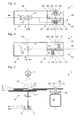
- Figure 1 shows a front view of a known from the prior art, variable Slit diaphragm 6 with two sliders arranged together on a line.
- the slot width 8 is by means of a micrometer screw (vertical Arrow), which selectively deforms an elastic ring (wholly double arrow), on which two opposing wedges symmetrically with respect to on an optical axis 10 away from each other (as shown) or each other can be approximated.
- FIG. 2 shows a front view of a slit diaphragm of a first invention Embodiment, arranged with two on two separate parallel lines Sliders to vary the slit width or slit height.
- Optical elements 4 include all common optical Devices such as grids, mirrors, fiber optic cables, lenses, and the like.
- Samples 5 include fluids such as solutions, suspensions and liquid-gas mixtures as well as solids, such as emulsions, tissue sections and cell cultures.
- the Device 1 comprises a slit diaphragm 6 with a slot height 7 and a Slot width 8, wherein the slot width 8 and / or the slot height 7 stepless are adjustable.
- the device according to the invention is characterized that the slit diaphragm 6 first and second parallel to each other on two separate comprises parallel lines arranged linearly movable slide 9,9 ', which in Reference to an optical axis 10 at least partially symmetrical to each other are mobile.
- each of the two slides 9,9 ' comprises at least one optical Opening 11,11 ', in the region of the optical axis 10 at least partially on the optical opening 11 ', 11 of the adjacent slide 9', 9 is positionable.
- a first slide position 23 In a first slide position 23 (see Fig. 2A) are the two slides 9,9 ' substantially congruent to each other and define a maximum gap width 8 at a first gap height 7, which is just the masses of the optical Apertures 11,11 'correspond. These optical openings 11,11 'are symmetrical here positioned to the optical axis 10.
- the further optical openings 14,14 ' also a round slot (see Fig. 4) or define any geometric surface.
- the Rotary axis 16 of the motor drive 15 for moving the two slides 9,9 ' is at right angles to this direction of movement 19, which is drawn as the axis of symmetry.
- the motor drive 15 comprises two pivotable about the axis of rotation 16 symmetrically Movement pin 17,17 ', which in each case a first mechanical opening 18,18 'in the two slides 9,9' intervene.
- the two slides 9,9 ' have second mechanical openings 20, 20 'spaced along the first one mechanical openings 18,18 'run, so that between the first and second mechanical openings 18, 18 ', 20, 20' spring webs 21, 21 'for play-free operation Holding the movement pins 17,17 'in the slides 9,9' are formed.
- the diameter of the movement pins 17, 17 ' is preferably slight greater than the width of the first mechanical openings 18,18 ', so that the spring bars 20,20 'when inserting the movement pins 17,17' in the first mechanical Openings 18,18 'must dodge elastic. This will be a play-free stop of the movement pins 17,17 'in the first mechanical openings 18,18 'guaranteed.
- the motor drive 15 preferably comprises a stepper motor with a reduction gear (not shown) and a hub 22 on which the in first mechanical openings 18,18 'of the slider 9,9' engaging movement pins 17,17 'are arranged so that they in a first slide position 23 lie on a line 24 which extends through the axis of rotation 16 and the at an angle of 90 ° to the direction of movement 19 of the slide 9,9 '(see. FIGS. 2 and 3) or deviating therefrom (cf., FIG. 4).
- FIG. 3 shows a front view of a slit diaphragm according to the invention second embodiment, arranged with two on two separate parallel lines Sliders for varying the gap width and / or gap height in a first Slider position, in which the two slides essentially congruent stand each other and a certain gap width and a maximum Define gap height.
- the optical openings 11,11 'in the two slides 9,9 'here have a mirror-symmetrical, pentagonal shape.
- FIG. 4 shows a front view of a slit diaphragm of a third invention Embodiment in which the fixed on the hub 22 movement pins 17,17 ', which in the first mechanical openings 18,18' of the slide 9,9 'are arranged so that they in a first slide position 23rd lie on a line 24 which extends through the axis of rotation 16 and the lower an angle of 45 ° to the direction of movement 19 of the slide 9,9 'extends.
- These Arrangement has the advantage that for a comparable slider movement a greater movement of the hub 22 is necessary, so that the slider movement can be controlled more precisely.
- FIG. 5 shows a sectional view of a slit diaphragm 6 according to the invention the fourth embodiment.
- the corresponding sectional profile is shown in FIG A - - A marked.
- This gap width 8 can by moving the slider 9,9 'or by adding the Slider 9 "can be determined, this adding automatically or motor driven.
- Light of the light source 2, focusing on the optical Axis 10 is penetrates the slit diaphragm and acts on one of these Slit diaphragm 6 defined field 3, which here is the surface of a sample 5, which is located in a well 44 of a microplate 43.
- This sample is from the excitation light permeated, so that physically or at least functionally in the Optical axis detector (not shown) triggered by the sample and / or can detect reflected or scattered light.
- the motor drive 15 for moving is particularly easy to see in FIG the two slides 9,9 ', which two symmetrically about the axis of rotation 16th pivotable movement pins 17,17 'includes.
- the movement pin shown here 27 engages in the first mechanical opening 18 in the slide 9.
- These first mechanical openings 18 is here by a two-sided spring bar 21st separated from the parallel second mechanical openings 20.
- Of the Moving pin 17 is characterized on both sides resilient and backlash in the slide. 9 held.
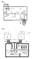
- Figure 6 shows a partial section through a three slit diaphragm 6 comprehensive Monochromator 32 for a system 31 for measuring fluorescence and / or luminescence and / or absorption of light irradiated with light from a light source 2 Samples 5.
- Light from the light source 2 occurs here along the optical Axis 10 through the so-called input gap 36 defining slit 6 of a first device 1 and strikes a field 3 of an optical element 4 in the form of a first grid 33.
- the light is mirrored at this first grid 33, occurs along the optical axis 10 through the so-called center gap 35 defining slit 6 of a second device 1 and hits a field 3 of an optical element 4 in the form of a second grating 34.
- the light is mirrored at this second grid 34, occurs along the optical axis 10th by the so-called output gap 37 defining slit 6 a third device 1 and impinges on a light-conducting fiber or a light-conducting Fiber bundles 38 with a certain diameter 39.
- This photoconductive fiber or this photoconductive fiber bundle 38 conducts the now monochromatic light to a sample 5 (see Fig. 7).
- the grids are arranged in this way that add the dispersions of the two grids 33,34. That of the first monochromator generated spectrum is further split by the 2nd monochromator.
- the gratings are arranged in this way that the dispersions of the two 33,34 lattices subtract.
- subtractive setup so only the purpose to improve the stray light suppression.
- Slit width 8 therefore advantageously produces a subtractive monochromator Light with double spectral bandwidth and therefore more energy.
- the entrance and middle gap of the monochromator to move; the exit slit may have a fixed width, whereby a simpler mechanics can be used.
- FIG. 7 shows a schematic layout of a system constructed as a multifunctional reader 31 for measuring fluorescence and / or luminescence and / or absorption of irradiated with the light from a light source 2 samples 5 with an excitation monochromator 32 and an emission monochromator 32 ', according to the construction principle in Fig. 6.
- the left monochromator 32 is like the transmitter (flash lamp 2 with adjustable wavelength and bandwidth) the right monochromator 32 'functions as a tunable wavelength and bandwidth detector 53.
- the diameter 39 of the well is illuminating fiber bundle or the well-illuminating optical fiber 38th limited in principle upwards.
- the width of the fiber bundle on the monochromator side is then limited at given gap height 7 also upwards.
- the gap width 8 of the exit slit 37 and therefore the achievable Bandwidth limited.
Landscapes
- Physics & Mathematics (AREA)
- Health & Medical Sciences (AREA)
- Spectroscopy & Molecular Physics (AREA)
- General Physics & Mathematics (AREA)
- Chemical & Material Sciences (AREA)
- Analytical Chemistry (AREA)
- Biochemistry (AREA)
- General Health & Medical Sciences (AREA)
- Life Sciences & Earth Sciences (AREA)
- Immunology (AREA)
- Pathology (AREA)
- Nuclear Medicine, Radiotherapy & Molecular Imaging (AREA)
- Investigating, Analyzing Materials By Fluorescence Or Luminescence (AREA)
- Spectrometry And Color Measurement (AREA)
- Electron Tubes For Measurement (AREA)
- Mechanical Light Control Or Optical Switches (AREA)
Abstract
Description
- Es wird ein einfacher Mechanismus vorgeschlagen, der es erlaubt, Systeme zum Messen der Fluoreszenz und/oder Lumineszenz und/oder Absorption von mit dem Licht aus einer Lichtquelle bestrahlten Proben - insbesondere Mulitfunktions-Reader mit mehreren solchen Schlitzblenden - kostengünstiger herzustellen.
- Die Schlitzbreite und/oder Schlitzhöhe kann jederzeit, also auch während dem Bestrahlen einer Probe, praktisch stufenlos verändert werden.
- Die Schlitzbreite kann auch, entsprechend voreingestellten Parametern, automatisch verändert oder an ein bestimmtes Probenverhalten angepasst werden.
- Fig. 1
- eine Frontansicht einer aus dem Stand der Technik bekannten, variablen Schlitzblende mit zwei gemeinsam auf einer Line angeordneten Schiebern;
- Fig. 2
- eine Frontansicht einer erfindungsgemässen Schlitzblende einer ersten
Ausführungsform, mit zwei auf zwei separaten parallelen Linien angeordneten
Schiebern zum Variieren der Spaltbreite oder der Spalthöhe,
wobei:
- Fig. 2A
- eine erste Schieberstellung zeigt, bei welcher die beiden Schieber im wesentlichen deckungsgleich zueinander stehen und eine maximale Spaltbreite bei einer ersten Spalthöhe definieren;
- Fig. 2B
- eine zweite Schieberstellung zeigt, bei welcher die beiden Schieber etwas gegen einander verschoben sind, so dass eine mittlere Spaltbreite bei einer ersten Spalthöhe resultiert;
- Fig. 2C
- eine dritte Schieberstellung zeigt, bei welcher die beiden Schieber mehr gegen einander verschoben sind, so dass eine minimale Spaltbreite bei einer ersten Spalthöhe resultiert;
- Fig. 2D
- eine vierte Schieberstellung zeigt, bei welcher die beiden Schieber weiter gegen einander verschoben sind, so dass eine feste Spaltbreite mit einer zweiten, reduzierten Spalthöhe resultiert;
- Fig. 3
- eine Frontansicht einer erfindungsgemässen Schlitzblende einer zweiten Ausführungsform, mit zwei auf zwei separaten parallelen Linien angeordneten Schiebern zum Variieren der Spaltbreite und/oder Spalthöhe in einer ersten Schieberstellung, bei welcher die beiden Schieber im wesentlichen deckungsgleich zueinander stehen und eine bestimmte Spaltbreite und eine maximale Spalthöhe definieren;
- Fig. 4
- eine Frontansicht einer erfindungsgemässen Schlitzblende einer dritten Ausführungsform, mit zwei auf zwei separaten parallelen Linien angeordneten Schiebern zum Variieren der Spaltbreite oder der Spalthöhe in einer ersten Schieberstellung, bei welcher die beiden Schieber im wesentlichen deckungsgleich zueinander stehen und eine maximale Spaltbreite bei einer ersten Spalthöhe definieren;
- Fig. 5
- eine Schnittdarstellung einer erfindungsgemässen Schlitzblende einer vierten Ausführungsform, mit drei auf drei separaten parallelen Linien angeordneten Schiebern gemäss Fig. 3 in einer ersten Schieberstellung, bei welcher die beiden Schieber im wesentlichen deckungsgleich zueinander stehen und eine erste Spaltbreite bei einer maximalen Spalthöhe definieren;
- Fig. 6
- einen Teilschnitt durch einen drei Schlitzblenden umfassenden Monochromator für ein System zum Messen der Fluoreszenz und/oder Lumineszenz und/oder Absorption von mit dem Licht aus einer Lichtquelle bestrahlten Proben;
- Fig. 7
- ein Schema-Layout eines als Multifunktions-Reader gebauten Systems zum Messen der Fluoreszenz und/oder Lumineszenz und/oder Absorption von mit dem Licht aus einer Lichtquelle bestrahlten Proben mit einem Anregungs- und einem Emissions-Monochromator gemäss Fig. 6.
- Eine 1- bis 4-Kanal-Optik 47 für Absorptionsmessungen;
- "Top"-Optiken 48,49 zum Messen der Fluoreszenz-Intensität;
- "Top"-Optiken 50 zum Messen der Lumineszenz-Intensität;
- LED-Licht-Quelle;
- Photonenzählende Detektoren 52, die vorzugsweise als PMT ausgebildet sind.
Claims (24)
- Vorrichtung (1) - zum Begrenzen eines mit Licht aus einer Lichtquelle (2) beaufschlagten Feldes (3), insbesondere auf der Oberfläche eines optischen Elements (4) bzw. einer Probe (5), - mit einer eine Schlitzhöhe (7) und eine Schlitzbreite (8) umfassenden Schlitzblende (6), die erste und zweite parallel zueinander auf zwei separaten parallelen Linien angeordnete, linear bewegliche Schieber (9,9') umfasst, welche in Bezug auf eine optische Achse (10) zumindest teilweise symmetrisch zueinander beweglich sind, wobei jeder der beiden Schieber (9,9') zumindest eine optische Öffnung (11,11') umfasst, die - zum stufenlosen Verstellen zumindest der Schlitzhöhe (7) oder der Schlitzbreite (8) - im Bereich der optischen Achse (10) zumindest teilweise auf der optischen Öffnung (11',11) des Nachbarschiebers (9',9) positionierbar ist, dadurch gekennzeichnet, dass die Vorrichtung (1) einen Motorantrieb (15) mit einer Drehachse (16) zum Bewegen der beiden Schieber (9,9') in einer Bewegungsrichtung (19) umfasst, wobei diese Drehachse (16) des Motorantriebs (15) rechtwinklig zu dieser Bewegungsrichtung (19) angeordnet ist.
- Vorrichtung (1) nach Anspruch 1, dadurch gekennzeichnet, dass die optischen Öffnungen (11,11') in den beiden Schiebern (9,9') eine zu einander identische oder spiegelsymmetrische Form aufweisen.
- Vorrichtung (1) nach Anspruch 2, dadurch gekennzeichnet, dass die optischen Öffnungen (11,11') in den beiden Schiebern (9,9'), zur Erzeugung einer variablen Schlitzbreite (8) bei konstanter Schlitzhöhe (7), eine rechteckige Form aufweisen.
- Vorrichtung (1) nach Anspruch 2, dadurch gekennzeichnet, dass die optischen Öffnungen (11,11') in den beiden Schiebern (9,9'), zur Erzeugung einer variablen Schlitzbreite (8) bei konstanter Schlitzhöhe (7) oder einer variablen Schlitzhöhe (7) bei variabler Schlitzbreite (8), eine fünfeckige Form aufweisen.
- Vorrichtung (1) nach Anspruch 4, dadurch gekennzeichnet, dass ein dritter Schieber (9") parallel zu den beiden Schiebern (9,9') angeordnet ist und eine schmale optische Öffnung (11") umfasst, welche im Bereich der optischen Achse (10) zumindest teilweise auf den optischen Öffnungen (11,11') der beiden Schieber (9,9') und in sich symmetrisch zu dieser optischen Achse (10) positionierbar ist.
- Vorrichtung (1) nach Anspruch 1, dadurch gekennzeichnet, dass der erste Schieber (9), zur Erzeugung einer variablen Schlitzhöhe (7), eine optische Öffnung (11) umfasst, die eine fünfeckige Form aufweist, und dass ein zweiter Schieber (9') eine optische Öffnung (11') umfasst, die eine schmale rechteckige Form aufweist.
- Vorrichtung (1) nach einem der vorhergehenden Ansprüche, dadurch gekennzeichnet, dass die beiden Schieber (9,9') weitere aufeinander positionierbare optische Öffnungen (14,14') umfassen, welche eine zu einander identische, rechteckige oder runde Form aufweisen.
- Vorrichtung (1) nach einem der vorhergehenden Ansprüche, dadurch gekennzeichnet, dass der Motorantrieb (15) zum Bewegen der beiden Schieber (9,9') zwei symmetrisch um die Drehachse (16) schwenkbare Bewegungszapfen (17,17') umfasst, welche in je eine erste mechanische Öffnung (18,18') in den beiden Schiebern (9,9') eingreifen.
- Vorrichtung (1) nach Anspruch 8, dadurch gekennzeichnet, dass die ersten mechanischen Öffnungen (18,18') in den beiden Schiebern (9,9') länglich und jeweils rechtwinklig zur Bewegungsrichtung (19) der Schieber (9,9') angeordnet sind.
- Vorrichtung (1) nach Anspruch 9, dadurch gekennzeichnet, dass die beiden Schieber (9,9') zweite mechanische Öffnungen (20,20') aufweisen, die beabstandet entlang der ersten mechanischen Öffnungen (18,18') verlaufen, so dass zwischen den ersten und zweiten mechanischen Öffnungen (18,18';20,20') Federstege (21,21') zum spielfreien Halten der Bewegungszapfen (17,17') in den Schiebern (9,9') gebildet werden.
- Vorrichtung (1) nach einem der vorhergehenden Ansprüche 8 bis 10, dadurch gekennzeichnet, dass der Motorantrieb (15) eine Drehscheibe (22) umfasst, auf der die in die ersten mechanischen Öffnungen (18,18') der Schieber (9,9') eingreifenden Bewegungszapfen (17,17') so angeordnet sind, dass sie in einer ersten Schieberstellung (23) auf einer Linie (24) liegen, die sich durch die Drehachse (16) erstreckt und die unter einem Winkel von 90° zur Bewegungsrichtung (19) der Schieber (9,9') oder davon abweichend verläuft.
- Vorrichtung (1) nach einem der vorhergehenden Ansprüche, dadurch gekennzeichnet, dass die Drehachse der Drehscheibe (22) mit der Drehachse (16) des Motorantriebs (15) identisch ist.
- Vorrichtung (1) nach einem der vorhergehenden Ansprüche, dadurch gekennzeichnet, dass die Schieber (9,9',9") aus Federstahl, insbesondere aus Federstahl-Blech, ausgebildet sind.
- Vorrichtung (1) nach einem der vorhergehenden Ansprüche, dadurch gekennzeichnet, dass die Schieber (9,9',9") zumindest im Bereich der optischen Öffnungen (11,11',11";14,14') schwarz mattiert sind.
- System (31) zum Messen zumindest eines der Signale ausgewählt aus der Gruppe Fluoreszenz, Lumineszenz und Absorption von mit dem Licht aus einer Lichtquelle (2) bestrahlten Proben (5), wobei das System (31) zumindest einen Monochromator (32) oder ein Spektrometer mit optischen Elementen (4) umfasst und dadurch gekennzeichnet ist, dass es zumindest eine Vorrichtung (1) gemäss einem oder mehreren der Ansprüche 1 bis 14 umfasst.
- System (31) nach Anspruch 15, dadurch gekennzeichnet, dass die optischen Elemente (4) des Monochromators (32) ein erstes und zweites Gitter (33,34) umfassen, zwischen denen eine Schlitzblende (6) zum Erzeugen eines Mittelspalts (35) angeordnet ist.
- System (31) nach Anspruch 16, dadurch gekennzeichnet, dass die optischen Elemente (4) des Monochromators (32) eine dem ersten Gitter (33) vorgeschaltete Schlitzblende (6) zum Erzeugen eines Eingangsspalts (36) und eine dem zweiten Gitter (34) nachgeschaltete Schlitzblende (6) zum Erzeugen eines Ausgangsspalts (37) umfassen.
- System (31) nach Anspruch 16 oder 17, dadurch gekennzeichnet, dass am Ausgangsspalt (37) des Monochromators (32) zumindest eine lichtleitende Faser (38) mit einem Durchmesser (39) anschliessbar ist.
- System nach Anspruch 18, dadurch gekennzeichnet, dass es zwei Monochromatoren (32) umfasst, an deren Eingangs- bzw. Ausgangsspalten (36,37) je ein Faserschieber (40) angeordnet ist, mit welchem mindestens je zwei lichtleitende Fasern (38) eines faseroptischen Systems (41) anschliessbar sind.
- System (31) nach einem der Ansprüche 15 bis 19, dadurch gekennzeichnet, dass es eine Halterung (42) zum Halten von Mikroplatten (43) umfasst, in deren Wells (44) Proben (5) anordenbar sind.
- System (31) nach Anspruch 20, dadurch gekennzeichnet, dass die Halterung (42) mit einer oder mehreren Mikroplatten (43) in einer im Wesentlichen horizontalen Ebene (45) in einer X- und in einer dazu rechtwinklig verlaufenden Y-Richtung gezielt bewegbar ist.
- System (31) nach einem der Ansprüche 15 bis 21, dadurch gekennzeichnet, dass es zumindest eine Optik (46) umfasst, die im Wesentlichen rechtwinklig zur Ebene (45) in Z-Richtung an im System (31) gehaltene Proben (5) annäherbar ausgebildet ist.
- Verfahren zum Begrenzen eines mit Licht aus einer Lichtquelle (2) beaufschlagten Feldes (3), insbesondere auf der Oberfläche eines optischen Elements (4) bzw. einer Probe (5), bei welchem eine Vorrichtung (1) mit einer Schlitzblende (6) verwendet wird, von der zumindest die Schlitzhöhe (7) oder die Schlitzbreite (8) stufenlos verstellbar ist, wobei die Schlitzbreite (8) der Schlitzblende (6) mit einem ersten und zweiten parallel zueinander angeordneten Schieber (9,9') eingestellt wird, indem diese beiden Schieber (9,9') in Bezug auf eine optische Achse (10) zumindest partiell symmetrisch zueinander linear bewegt werden, bis ein gewünschter Spalt durch ein zumindest teilweises Überlappen von in jedem Schieber (9,9') angeordneten optischen Öffnungen (11,11') im Bereich der optischen Achse (10) erhalten wird, dadurch gekennzeichnet, dass die beiden Schieber (9,9') der Vorrichtung (1) mit einem Motorantrieb (15) in einer Bewegungsrichtung (19) bewegt werden, wobei der Motorantrieb (15) eine Drehachse (16) umfasst, die rechtwinklig zu dieser Bewegungsrichtung (19) angeordnet ist.
- Verfahren nach Anspruch 23, dadurch gekennzeichnet, dass der Motorantrieb (15) zwei symmetrisch um seine Drehachse (16) schwenkbare Bewegungszapfen (17,17') umfasst, welche in je eine erste mechanische Öffnung (18,18') in den beiden Schiebern (9,9') eingreifen.
Applications Claiming Priority (2)
| Application Number | Priority Date | Filing Date | Title |
|---|---|---|---|
| CH12302003 | 2003-07-14 | ||
| CH12302003 | 2003-07-14 |
Publications (2)
| Publication Number | Publication Date |
|---|---|
| EP1498707A1 true EP1498707A1 (de) | 2005-01-19 |
| EP1498707B1 EP1498707B1 (de) | 2009-11-11 |
Family
ID=33459814
Family Applications (1)
| Application Number | Title | Priority Date | Filing Date |
|---|---|---|---|
| EP04015838A Expired - Lifetime EP1498707B1 (de) | 2003-07-14 | 2004-07-06 | Schlitzblende in einem Monochromator |
Country Status (4)
| Country | Link |
|---|---|
| US (1) | US7123398B2 (de) |
| EP (1) | EP1498707B1 (de) |
| AT (1) | ATE448472T1 (de) |
| DE (1) | DE502004010336D1 (de) |
Cited By (2)
| Publication number | Priority date | Publication date | Assignee | Title |
|---|---|---|---|---|
| WO2012016761A1 (de) * | 2010-08-02 | 2012-02-09 | Leica Microsystems Cms Gmbh | Einrichtung zur lückenlosen einstellung von spektrometer-spaltbreiten |
| EP2758824B1 (de) * | 2011-09-23 | 2020-04-22 | Carl Zeiss Microscopy GmbH | Vorrichtung und verfahren zur durchlichtbeleuchtung für lichtmikroskope und mikroskopsystem |
Families Citing this family (6)
| Publication number | Priority date | Publication date | Assignee | Title |
|---|---|---|---|---|
| FI20085062A0 (fi) * | 2008-01-25 | 2008-01-25 | Wallac Oy | Parannettu mittausjärjestelmä ja -menetelmä |
| US9726984B2 (en) * | 2013-07-09 | 2017-08-08 | Kla-Tencor Corporation | Aperture alignment in scatterometry metrology systems |
| CH709896A2 (de) | 2014-07-18 | 2016-01-29 | Tecan Trading Ag | Monochromator mit schwingungsarm bewegbaren optischen Elementen. |
| JP6466496B2 (ja) * | 2017-04-05 | 2019-02-06 | Ckd株式会社 | 検査装置、ptp包装機及びptpシートの製造方法 |
| CN107991724A (zh) * | 2017-12-29 | 2018-05-04 | 深圳开立生物医疗科技股份有限公司 | 光路补偿装置及冷光源系统 |
| CN119882219B (zh) * | 2025-03-25 | 2025-12-26 | 奥谱天成(厦门)光电有限公司 | 一种微米级电动连续可调狭缝装置及光学装置 |
Citations (5)
| Publication number | Priority date | Publication date | Assignee | Title |
|---|---|---|---|---|
| GB2084758A (en) * | 1980-10-06 | 1982-04-15 | Perkin Elmer Corp | Optical slit apparatus |
| JPS6039533A (ja) * | 1983-08-12 | 1985-03-01 | Japan Spectroscopic Co | マイクロプレ−ト分光分析装置 |
| EP0482765A1 (de) * | 1990-09-29 | 1992-04-29 | Shimadzu Corporation | Monochromator mit speziell geformten Spalten |
| US5627671A (en) * | 1993-11-08 | 1997-05-06 | Jasco Corporation | Spectrometer slit switching mechanism |
| US5885531A (en) * | 1995-03-16 | 1999-03-23 | Bio-Rad Laboratories, Inc. | Fluorescence imaging instrument utilizing fish |
Family Cites Families (10)
| Publication number | Priority date | Publication date | Assignee | Title |
|---|---|---|---|---|
| US48442A (en) * | 1865-06-27 | Improved washing-machine | ||
| JPS5562321A (en) * | 1978-11-02 | 1980-05-10 | Hitachi Ltd | Spectrophotometer |
| FR2530041A1 (fr) * | 1982-07-09 | 1984-01-13 | Omera Segid | Obturateur photographique a rideaux |
| US5233405A (en) * | 1991-11-06 | 1993-08-03 | Hewlett-Packard Company | Optical spectrum analyzer having double-pass monochromator |
| JP3708246B2 (ja) * | 1996-09-19 | 2005-10-19 | オリンパス株式会社 | 光制御部材を有する光学顕微鏡 |
| US5854487A (en) * | 1997-02-28 | 1998-12-29 | Park Scientific Instruments | Scanning probe microscope providing unobstructed top down and bottom up views |
| JP4273372B2 (ja) * | 1998-07-31 | 2009-06-03 | ソニー株式会社 | 撮像装置 |
| US6336752B1 (en) * | 1999-11-19 | 2002-01-08 | Lockheed Martin Corporation | Dual motor reciprocating belt shutter |
| DE10147481A1 (de) * | 2001-09-26 | 2003-04-17 | Zeiss Carl Jena Gmbh | Pinhole-Blende für die Laserscanningmikroskopie |
| KR20050006415A (ko) * | 2003-07-08 | 2005-01-17 | 삼성전자주식회사 | 조명유닛 및 이를 구비하는 투사형 화상표시장치 |
-
2004
- 2004-07-06 DE DE502004010336T patent/DE502004010336D1/de not_active Expired - Lifetime
- 2004-07-06 AT AT04015838T patent/ATE448472T1/de active
- 2004-07-06 EP EP04015838A patent/EP1498707B1/de not_active Expired - Lifetime
- 2004-07-12 US US10/889,650 patent/US7123398B2/en not_active Expired - Fee Related
Patent Citations (5)
| Publication number | Priority date | Publication date | Assignee | Title |
|---|---|---|---|---|
| GB2084758A (en) * | 1980-10-06 | 1982-04-15 | Perkin Elmer Corp | Optical slit apparatus |
| JPS6039533A (ja) * | 1983-08-12 | 1985-03-01 | Japan Spectroscopic Co | マイクロプレ−ト分光分析装置 |
| EP0482765A1 (de) * | 1990-09-29 | 1992-04-29 | Shimadzu Corporation | Monochromator mit speziell geformten Spalten |
| US5627671A (en) * | 1993-11-08 | 1997-05-06 | Jasco Corporation | Spectrometer slit switching mechanism |
| US5885531A (en) * | 1995-03-16 | 1999-03-23 | Bio-Rad Laboratories, Inc. | Fluorescence imaging instrument utilizing fish |
Non-Patent Citations (1)
| Title |
|---|
| PATENT ABSTRACTS OF JAPAN vol. 0091, no. 63 (P - 371) 9 July 1985 (1985-07-09) * |
Cited By (3)
| Publication number | Priority date | Publication date | Assignee | Title |
|---|---|---|---|---|
| WO2012016761A1 (de) * | 2010-08-02 | 2012-02-09 | Leica Microsystems Cms Gmbh | Einrichtung zur lückenlosen einstellung von spektrometer-spaltbreiten |
| US8837044B2 (en) | 2010-08-02 | 2014-09-16 | Leica Microsystems Cms Gmbh | Device for continuous adjustment of spectrometer gap widths |
| EP2758824B1 (de) * | 2011-09-23 | 2020-04-22 | Carl Zeiss Microscopy GmbH | Vorrichtung und verfahren zur durchlichtbeleuchtung für lichtmikroskope und mikroskopsystem |
Also Published As
| Publication number | Publication date |
|---|---|
| DE502004010336D1 (de) | 2009-12-24 |
| US20050030607A1 (en) | 2005-02-10 |
| EP1498707B1 (de) | 2009-11-11 |
| ATE448472T1 (de) | 2009-11-15 |
| US7123398B2 (en) | 2006-10-17 |
Similar Documents
| Publication | Publication Date | Title |
|---|---|---|
| DE2364069C3 (de) | Spektralphotometer | |
| EP1754032B1 (de) | Echelle-spektrometer mit verbesserter detektorausnutzung durch die verwendung zweier spektrometeranordnungen | |
| DE3339006C2 (de) | Schlitzmechanismus zur Verwendung in einem Monochromator | |
| EP1498707B1 (de) | Schlitzblende in einem Monochromator | |
| DE19710143A1 (de) | Hadamard-Spektrometer | |
| DE19509157C2 (de) | Optisches System mit großen Meßbereichen | |
| EP0587683B1 (de) | Echelle-polychromator | |
| EP3139147A1 (de) | Vorrichtung und verfahren zur messung einer wellenlängenabhängigen optischen kenngrösse eines optischen systems | |
| DE102006036504A1 (de) | Vorrichtung und Verfahren zur Messung des Höhenprofils eines strukturierten Substrats | |
| DE102022112766A1 (de) | Spektrometersystem zur laserinduzierten Plasmaspektralanalyse | |
| EP3499200A1 (de) | Durchstimmbarer filtermonochromator | |
| EP2163883B1 (de) | Partikelgrössenmessgerät | |
| DE102008064760B3 (de) | Partikelgrößenmessgerät | |
| DE3942375A1 (de) | Vorrichtung zur gleichzeitigen erfassung mehrerer wellenlaengenbereiche | |
| EP2663854A1 (de) | Vorrichtung zur messung von optischen eigenschaften von proben in mikroplatten | |
| DE3005352A1 (de) | Optische anordnung zum erzeugen von zeitlich aufeinanderfolgenden messstrahlenbuendeln unterschiedlicher wellenlaenge | |
| DE4441686A1 (de) | Sortiervorrichtung | |
| DE2604666A1 (de) | Monochromator zur nutzung zweier wellenlaengen | |
| DE19543729B4 (de) | Spektrometer | |
| DE69502915T2 (de) | Herstellungsverfahren eines reflektierenden optischen Beugungsgitters | |
| DE2813908A1 (de) | Verfahren und vorrichtung zur spektralphotometrischen farbbestimmung | |
| DE69107776T2 (de) | Monochromator mit speziell geformten Spalten. | |
| DE102008047370A1 (de) | Partikelgrößenmessgerät | |
| DE102022112765B4 (de) | Detektionseinheit zur spektralen Analyse eines laserinduzierten Plasmas und laserinduziertes Plasmaspektrometer | |
| DE102006011277A1 (de) | Laser-Scanning-Mikroskop und Laser-Scanning-Mikroskopierverfahren |
Legal Events
| Date | Code | Title | Description |
|---|---|---|---|
| PUAI | Public reference made under article 153(3) epc to a published international application that has entered the european phase |
Free format text: ORIGINAL CODE: 0009012 |
|
| AK | Designated contracting states |
Kind code of ref document: A1 Designated state(s): AT BE BG CH CY CZ DE DK EE ES FI FR GB GR HU IE IT LI LU MC NL PL PT RO SE SI SK TR |
|
| AX | Request for extension of the european patent |
Extension state: AL HR LT LV MK |
|
| 17P | Request for examination filed |
Effective date: 20050601 |
|
| AKX | Designation fees paid |
Designated state(s): AT CH DE FR GB LI |
|
| 17Q | First examination report despatched |
Effective date: 20061214 |
|
| GRAP | Despatch of communication of intention to grant a patent |
Free format text: ORIGINAL CODE: EPIDOSNIGR1 |
|
| RTI1 | Title (correction) |
Free format text: SLIT DIAPHRAGM IN A MONOCHROMATOR |
|
| RIN1 | Information on inventor provided before grant (corrected) |
Inventor name: PUCHEGGER, KARL Inventor name: NIGGL, LUTZ |
|
| GRAS | Grant fee paid |
Free format text: ORIGINAL CODE: EPIDOSNIGR3 |
|
| GRAA | (expected) grant |
Free format text: ORIGINAL CODE: 0009210 |
|
| AK | Designated contracting states |
Kind code of ref document: B1 Designated state(s): AT CH DE FR GB LI |
|
| REG | Reference to a national code |
Ref country code: GB Ref legal event code: FG4D Free format text: NOT ENGLISH |
|
| REG | Reference to a national code |
Ref country code: CH Ref legal event code: EP |
|
| REF | Corresponds to: |
Ref document number: 502004010336 Country of ref document: DE Date of ref document: 20091224 Kind code of ref document: P |
|
| REG | Reference to a national code |
Ref country code: CH Ref legal event code: NV Representative=s name: OK PAT AG PATENTE MARKEN LIZENZEN |
|
| PLBE | No opposition filed within time limit |
Free format text: ORIGINAL CODE: 0009261 |
|
| STAA | Information on the status of an ep patent application or granted ep patent |
Free format text: STATUS: NO OPPOSITION FILED WITHIN TIME LIMIT |
|
| 26N | No opposition filed |
Effective date: 20100812 |
|
| GBPC | Gb: european patent ceased through non-payment of renewal fee |
Effective date: 20100706 |
|
| REG | Reference to a national code |
Ref country code: FR Ref legal event code: ST Effective date: 20110331 |
|
| PG25 | Lapsed in a contracting state [announced via postgrant information from national office to epo] |
Ref country code: FR Free format text: LAPSE BECAUSE OF NON-PAYMENT OF DUE FEES Effective date: 20100802 |
|
| PG25 | Lapsed in a contracting state [announced via postgrant information from national office to epo] |
Ref country code: GB Free format text: LAPSE BECAUSE OF NON-PAYMENT OF DUE FEES Effective date: 20100706 |
|
| PGFP | Annual fee paid to national office [announced via postgrant information from national office to epo] |
Ref country code: DE Payment date: 20170627 Year of fee payment: 14 Ref country code: CH Payment date: 20170711 Year of fee payment: 14 |
|
| PGFP | Annual fee paid to national office [announced via postgrant information from national office to epo] |
Ref country code: AT Payment date: 20170626 Year of fee payment: 14 |
|
| REG | Reference to a national code |
Ref country code: DE Ref legal event code: R119 Ref document number: 502004010336 Country of ref document: DE |
|
| REG | Reference to a national code |
Ref country code: CH Ref legal event code: PL |
|
| REG | Reference to a national code |
Ref country code: AT Ref legal event code: MM01 Ref document number: 448472 Country of ref document: AT Kind code of ref document: T Effective date: 20180706 |
|
| PG25 | Lapsed in a contracting state [announced via postgrant information from national office to epo] |
Ref country code: LI Free format text: LAPSE BECAUSE OF NON-PAYMENT OF DUE FEES Effective date: 20180731 Ref country code: CH Free format text: LAPSE BECAUSE OF NON-PAYMENT OF DUE FEES Effective date: 20180731 Ref country code: AT Free format text: LAPSE BECAUSE OF NON-PAYMENT OF DUE FEES Effective date: 20180706 Ref country code: DE Free format text: LAPSE BECAUSE OF NON-PAYMENT OF DUE FEES Effective date: 20190201 |