EP1498519A1 - Strand orientation alignment in strand coating systems - Google Patents
Strand orientation alignment in strand coating systems Download PDFInfo
- Publication number
- EP1498519A1 EP1498519A1 EP04012825A EP04012825A EP1498519A1 EP 1498519 A1 EP1498519 A1 EP 1498519A1 EP 04012825 A EP04012825 A EP 04012825A EP 04012825 A EP04012825 A EP 04012825A EP 1498519 A1 EP1498519 A1 EP 1498519A1
- Authority
- EP
- European Patent Office
- Prior art keywords
- strand
- adhesive
- adhesive dispensing
- axial orientation
- dispensing device
- Prior art date
- Legal status (The legal status is an assumption and is not a legal conclusion. Google has not performed a legal analysis and makes no representation as to the accuracy of the status listed.)
- Granted
Links
Images


Classifications
-
- B—PERFORMING OPERATIONS; TRANSPORTING
- B05—SPRAYING OR ATOMISING IN GENERAL; APPLYING FLUENT MATERIALS TO SURFACES, IN GENERAL
- B05B—SPRAYING APPARATUS; ATOMISING APPARATUS; NOZZLES
- B05B13/00—Machines or plants for applying liquids or other fluent materials to surfaces of objects or other work by spraying, not covered by groups B05B1/00 - B05B11/00
- B05B13/02—Means for supporting work; Arrangement or mounting of spray heads; Adaptation or arrangement of means for feeding work
- B05B13/0207—Means for supporting work; Arrangement or mounting of spray heads; Adaptation or arrangement of means for feeding work the work being an elongated body, e.g. wire or pipe
-
- A—HUMAN NECESSITIES
- A61—MEDICAL OR VETERINARY SCIENCE; HYGIENE
- A61F—FILTERS IMPLANTABLE INTO BLOOD VESSELS; PROSTHESES; DEVICES PROVIDING PATENCY TO, OR PREVENTING COLLAPSING OF, TUBULAR STRUCTURES OF THE BODY, e.g. STENTS; ORTHOPAEDIC, NURSING OR CONTRACEPTIVE DEVICES; FOMENTATION; TREATMENT OR PROTECTION OF EYES OR EARS; BANDAGES, DRESSINGS OR ABSORBENT PADS; FIRST-AID KITS
- A61F13/00—Bandages or dressings; Absorbent pads
- A61F13/15—Absorbent pads, e.g. sanitary towels, swabs or tampons for external or internal application to the body; Supporting or fastening means therefor; Tampon applicators
- A61F13/15577—Apparatus or processes for manufacturing
- A61F13/15585—Apparatus or processes for manufacturing of babies' napkins, e.g. diapers
- A61F13/15593—Apparatus or processes for manufacturing of babies' napkins, e.g. diapers having elastic ribbons fixed thereto; Devices for applying the ribbons
-
- B—PERFORMING OPERATIONS; TRANSPORTING
- B05—SPRAYING OR ATOMISING IN GENERAL; APPLYING FLUENT MATERIALS TO SURFACES, IN GENERAL
- B05C—APPARATUS FOR APPLYING FLUENT MATERIALS TO SURFACES, IN GENERAL
- B05C5/00—Apparatus in which liquid or other fluent material is projected, poured or allowed to flow on to the surface of the work
- B05C5/02—Apparatus in which liquid or other fluent material is projected, poured or allowed to flow on to the surface of the work the liquid or other fluent material being discharged through an outlet orifice by pressure, e.g. from an outlet device in contact or almost in contact, with the work
- B05C5/0241—Apparatus in which liquid or other fluent material is projected, poured or allowed to flow on to the surface of the work the liquid or other fluent material being discharged through an outlet orifice by pressure, e.g. from an outlet device in contact or almost in contact, with the work for applying liquid or other fluent material to elongated work, e.g. wires, cables, tubes
-
- B—PERFORMING OPERATIONS; TRANSPORTING
- B05—SPRAYING OR ATOMISING IN GENERAL; APPLYING FLUENT MATERIALS TO SURFACES, IN GENERAL
- B05B—SPRAYING APPARATUS; ATOMISING APPARATUS; NOZZLES
- B05B7/00—Spraying apparatus for discharge of liquids or other fluent materials from two or more sources, e.g. of liquid and air, of powder and gas
- B05B7/02—Spray pistols; Apparatus for discharge
- B05B7/08—Spray pistols; Apparatus for discharge with separate outlet orifices, e.g. to form parallel jets, i.e. the axis of the jets being parallel, to form intersecting jets, i.e. the axis of the jets converging but not necessarily intersecting at a point
Definitions
- the disclosure relates generally to strand coating systems and methods, and more particularly to systems, sub-systems and methods for applying coatings to elongated strands having asymmetric cross sections, for example, the application of vacillating adhesive filaments to elastic strands having rectangular cross sections prior to adherence on a substrate or between substrates, methods and systems therefor.
- a vacillating meltblown adhesive filament is captured on an elastic strand drawn past a nozzle from which the adhesive is dispensed.
- the vacillating adhesive filament is substantially entirely captured by the strand as it tends to wrap around the strand, coating the sides thereof substantially uniformly along the strand axis prior to adherence of the strand onto a substrate in the manufacture of bodily fluid absorbing personal hygienic articles.
- the known exemplary strand coating systems and technologies discussed above work well for applying adhesive materials to elastic strands having substantially uniform cross-sections, for example, square or circular cross-sectional shapes.
- the adhesive or other substance is applied to a strand having an asymmetric cross sectional shape, for example, a substantially rectangular sectional shape.
- These applications include the application of adhesives onto natural rubber or elastic tape used in the manufacture of bodily fluid absorbent hygienic articles.
- the cross-sectional shape of the elastic strand is rectangular or asymmetric
- the known prior art adhesive coating systems tends to apply the adhesive material on the elastic strand unevenly. Specifically, the adhesive tends to adhere more on one side of the strand, for example, the wider edge thereof, than to other sides of the strand.
- the strand tends to flip from side to side as it is drawn along the strand guide resulting in the application of the adhesive material to different sides of the strand.
- the uneven application of adhesive material to the strand compromises the integrity of the bond, since some portions of the strand may be devoid of adhesive.
- the disclosure is drawn generally to systems, sub-systems and methods for controlling the orientation of at least a portion of a strand about its axial dimension as the strand portion is drawn past a fluid or liquid dispensing nozzle, for example, in an adhesive dispensing system that applies a hot melt adhesive filament from an adhesive dispensing orifice of an adhesive dispensing device or apparatus onto an elastic strand used in the manufacture of personal hygienic articles.
- these and other adhesive dispensing systems generally include a strand axial orientation aligning member.
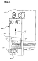
- FIGS. 2-4 illustrate an exemplary strand coating system 200 including generally an adhesive dispensing device 210 having one or more adhesive dispensing orifices.
- the adhesive dispensing device 210 includes first and second orifices 211 and 212 that each dispense an adhesive fiber or filament onto a corresponding strand.
- the adhesive filaments vacillate predominately transversely to the path of the corresponding strands.
- the adhesive dispensing system or device is a spiral nozzle that dispenses a generally helical filament or fiber.
- other filament dispensing devices may be used alternatively.
- the exemplary applications concern the application of adhesive fibers or filaments onto elastic strands, the disclosure has much wider applicability, including the application filaments onto other strand types, which are not necessarily elastic, and to the application of atomized liquids onto strands, for example, the application of atomized lubricants onto fibers, among other applications, as will be appreciated in view of the discussion below.
- the exemplary adhesive dispensing device 210 is mounted on a module 220 that controls the supply of adhesive and air or other gas to the adhesive dispensing device 210.
- the module may be operated pneumatically or electrically.
- the module 220 or similar device may also be used to control the supply of adhesive and/ or air to spiral nozzles and to other adhesive dispensing devices, for example, to spiral nozzles.
- the exemplary module 220 is mounted on a head 240, which provides a metered supply of adhesive or other material and air to the adhesive dispensing device via the module.
- the adhesive and any required gas may be provided to the nozzle by some other structure, for example, the adhesive dispensing orifices may be part of an integrated assembly rather than the modular assembly of the exemplary embodiment.
- the exemplary system of FIGS. 2-4 also includes an optional strand guide member 230 for guiding aligning the strand along a drawing path relative to the adhesive dispensing nozzle.
- the exemplary strand guide 230 is a strand guide roller having first and second grooves 232 and 234 for guiding corresponding strands 233 and 235 relative to corresponding orifices of the adhesive dispensing device 210.
- other types of strand guides may be used, for example, nonrotating strand guides.
- the strand guide is generally located upstream of the adhesive dispensing device and functions generally to align the path of one more strands with the adhesive dispensing device. In some embodiments, the strand guide is not required.
- the strand guide is preferably coupled to the adhesive dispensing device so that the strand guide and adhesive dispensing device vibrate in unison.
- the stand guide roller 230 is adjustably mounted on the head 240 by first and second adjustably positionable arms 236 and 238, which permit adjusting the spacing between the strands and the adhesive dispensing device and also permit adjusting the upstream location of the strand guide roller.
- the strand guide roller is not necessarily coupled to the adhesive dispensing device, and the strand guide position is not necessarily adjustable.
- At least one strand axial orientation aligning member is disposed proximate each orifice of the fluid or liquid dispensing device.
- the strand axial orientation aligning member is preferably disposed on an upstream side of adhesive dispensing device.
- a strand axial orientation aligning member 252 is positioned between each orifice of the fluid or liquid dispensing device and the strand guide roller 230.
- the strand axial orientation aligning member is positioned so that it is generally aligned, for example, on one side or the other thereof, is aligned with a corresponding orifice of the adhesive dispensing device.
- the strand is drawn so that it passes along the strand axial orientation aligning member and over or under a corresponding orifice of the fluid or liquid dispensing device.
- first and second strand axial orientation aligning members 250 and 252 are aligned generally with corresponding orifices 212 and 214, respectively, of the adhesive dispensing device 210.
- the exemplary strand axial orientation aligning members are mounted on a plate 254 fastened to the module 220.
- the exemplary strand axial orientation aligning member is a pin shaped member having an axis extending substantially transversely to a direction in which the strand is drawn past the adhesive dispensing device.
- the strand axial orientation aligning members are not mounted or otherwise coupled to the adhesive dispensing device, for example, the strand axial orientation aligning members may be mounted or supported by some other isolated structure.
- the strand axial orientation aligning member controls an orientation of at least a portion of the strand about its axial dimension as the strand portion is drawn past the adhesive dispensing nozzle.
- the strand axial orientation aligning member also precisely aligns the strand with the orifice of the adhesive dispensing device.
- the strand axial orientation aligning member controls the orientation of the strand portion by preventing twisting of the strand portion about its axial dimension at least in a neighborhood of the adhesive dispensing nozzle.
- the strand axial orientation aligning member fixes the orientation of the strand at least as the strand is drawn past the orifice of the adhesive dispensing nozzle.
- the exemplary strand axial orientation aligning member includes first and second flanges 256 and 257 separated by a guiding portion 258.
- the strand 235 is retained between the first and second flanges, thereby essentially fixing the distance between the strand and the adhesive dispensing device 210.
- Structure other than the strand axial orientation aligning member may be used alternatively to fix the distance between the strand and the device 210 in embodiments where it is desirable to control or fix the spacing between the strand and the orifice.
- the strand has at least one relatively flat side or surface along its axial dimension.
- the exemplary strand 510 has a substantially rectangular cross-sectional shape with major and minor axes or dimensions.
- the major dimension has flat sides 511 and 513 along the axial direction of the strand.
- the orientation of the strand portion about its axial dimension is controlled by engaging the substantially flat side of the strand with the strand axial orientation aligning member as the strand is drawn past the fluid or liquid dispensing device.
- the strand is oriented so that the major axis of the cross-sectional dimension of the strand is substantially parallel to the direction in which a vacillating adhesive filament 520 is dispensed from a dispensing device 530 by a similarly aligned strand axial orientation aligning member, which is not visible in FIG. 5.
- the strand orientation illustrated in FIG. 5 is desirable in some strand coating applications, for example, those where the strand is coated with a vacillating filament of fiber as illustrated in FIG. 5 to ensure that the strand is coated on both sides 512 and 514 along the major dimension or axis.
- the strand may be oriented at different angles by orientating the angle of the guiding surface of the strand axial orientation aligning member.
- the major dimension of the strand cross-section may be made substantially transverse to the direction of the adhesive flow with a transversely disposed strand axial orientation aligning member.
- the strand may be oriented at other angles.
- the strand tends to be coated on only one side thereof.
- the filament in FIG. 1 may be a substantially planar vacillating filament or a helical filament.
- the strand tends to twist back and forth about its axial dimension as it is drawn past the adhesive dispensing device, for example, where the strand is subject to vibration. If the twisting strand is symmetrical about its axial dimension the twisting thereof may not have an adverse affect on the application of adhesive onto the strand.
- twisting strand in applications where the twisting strand has a rectangular cross-section, the twisting strand tends to be coated on only one side thereof facing the orifice when the major dimension of the strand is transverse to the path of the adhesive filament. Thus a twisting strand having a rectangular cross-sectional dimension will not be uniformly coated with adhesive along its axial dimension.
- FIG. 6 illustrates an application where an adhesive coated strand 610 is bonded between first and second substrates 620 and 630, for example, in the manufacture of personal hygienic articles.
- an adhesive coated strand 610 is bonded between first and second substrates 620 and 630, for example, in the manufacture of personal hygienic articles.
- Orienting the strand as illustrated in FIG. 5, with a strand axial orientation aligning member will ensure uniform coating of the strand on opposite sides of the major dimension along the axial dimension of the strand.
- a tangential force is applied to the strand as the strand is drawn over the strand axial orientation aligning member by guiding the strand in a groove of the strand guide roller that is not aligned with the adhesive dispensing orifice, as illustrated best in FIG. 4.
- one of the grooves 232 or 234 of the strand guide roller guide the strand along a path that is misaligned with the orifices 212 and 214 of the adhesive dispensing device.
- a corresponding one of the strand axial orientation aligning members 250 or 252 change the direction of the strand 233 and 235 in alignment with the orifices 212 and 214.
- the tangential force biases the strand against the strand axial orientation aligning member as the strand is drawn past the adhesive dispensing device.
- the biasing force enables the strand axial orientation aligning member to maintain the desired orientation of the strand about its axial dimension at least in a neighborhood of the adhesive dispensing device.
- the strand may be captured between two strand axial orientation aligning members. In the alternative embodiment, it may by unnecessary to tangentially bias the strand about the strand axial orientation aligning member with a misaligned strand guide.
- a strand having an asymmetric cross-sectional shape is drawn past an adhesive dispensing nozzle.
- the strand is aligned along a drawing path relative to the adhesive dispensing nozzle before orienting the portion of the strand, for example with a strand guide roller.
- an orientation of at least a portion of the strand is maintained as the portion of the strand is drawn past the adhesive dispensing nozzle.
- the major dimension of the strand is aligned and fixed substantially parallel to a direction in which adhesive is dispensed from the adhesive dispensing nozzle.
- orientation includes preventing twisting of the portion of the strand oriented to maintain its orientation relative to the adhesive dispensing nozzle as the portion of the strand is drawn past the adhesive dispensing nozzle.
- a liquid or fluid for example, a hot melt adhesive is applied to the strand as the strand is drawn past the adhesive dispensing nozzle.
- applying adhesive to the strand as the strand is drawn past the adhesive dispensing nozzle includes capturing a vacillating filament dispensed from the adhesive dispensing nozzle on opposite sides of the strand substantially parallel to the direction in which adhesive is dispensed from the adhesive dispensing nozzle.
- the adhesive filament may not be vacillating, for example, it may be a spiral filament or a chaotic filament.
Landscapes
- Health & Medical Sciences (AREA)
- Engineering & Computer Science (AREA)
- Vascular Medicine (AREA)
- Epidemiology (AREA)
- Biomedical Technology (AREA)
- Heart & Thoracic Surgery (AREA)
- Manufacturing & Machinery (AREA)
- Life Sciences & Earth Sciences (AREA)
- Animal Behavior & Ethology (AREA)
- General Health & Medical Sciences (AREA)
- Public Health (AREA)
- Veterinary Medicine (AREA)
- Coating Apparatus (AREA)
- Application Of Or Painting With Fluid Materials (AREA)
Abstract
Description
In some embodiments, the strand is aligned along a drawing path relative to the adhesive dispensing nozzle before orienting the portion of the strand, for example with a strand guide roller.
Claims (7)
- A strand coating system, comprising:an adhesive dispensing device having an adhesive dispensing orifice;a strand guide member;a strand axial orientation aligning member coupled to the adhesive dispensing device,the strand axial orientation aligning member positioned in substantial alignment with the adhesive dispensing orifice, the strand axial orientation aligning member disposed between the strand guide member and the adhesive dispensing orifice.
- The strand coating system of Claim 1, the strand axial orientation aligning member is a pin having an axis extending substantially transverse to a direction in which a strand is drawn past the adhesive dispensing device.
- The strand coating system of Claim 1,
adhesive dispensing device includes an adhesive dispensing nozzle apparatus coupled to a module,
the strand axial orientation aligning member coupled to the module. - The strand coating system of Claim 3, the strand axial orientation aligning member is a pin having an axis extending substantially parallel to a direction in which adhesive is dispensed from the adhesive dispensing orifice.
- The strand coating system of Claim 3, the strand guide member ist coupled to the module.
- The strand coating system of Claim 5, the strand guide member is strand guide roller adjustably coupled to the module.
- The strand coating system of Claim 1, the strand guide member includes a strand guide not aligned with the adhesive dispensing orifice.
Applications Claiming Priority (2)
| Application Number | Priority Date | Filing Date | Title |
|---|---|---|---|
| US623294 | 2003-07-18 | ||
| US10/623,294 US7485187B2 (en) | 2003-07-18 | 2003-07-18 | Strand orientation alignment in strand coating systems and methods |
Publications (2)
| Publication Number | Publication Date |
|---|---|
| EP1498519A1 true EP1498519A1 (en) | 2005-01-19 |
| EP1498519B1 EP1498519B1 (en) | 2017-08-02 |
Family
ID=33477146
Family Applications (1)
| Application Number | Title | Priority Date | Filing Date |
|---|---|---|---|
| EP04012825.8A Expired - Lifetime EP1498519B1 (en) | 2003-07-18 | 2004-05-29 | Strand orientation alignment in strand coating systems |
Country Status (6)
| Country | Link |
|---|---|
| US (2) | US7485187B2 (en) |
| EP (1) | EP1498519B1 (en) |
| JP (1) | JP4699717B2 (en) |
| CN (1) | CN100404144C (en) |
| CA (1) | CA2473364C (en) |
| MX (1) | MXPA04006851A (en) |
Families Citing this family (8)
| Publication number | Priority date | Publication date | Assignee | Title |
|---|---|---|---|---|
| MX2011000634A (en) * | 2010-01-18 | 2011-11-04 | Basf Se | Strand guide assembly and method of controlling a flow of molten thermoplastic. |
| US9718084B2 (en) | 2014-01-21 | 2017-08-01 | Illinois Tool Works Inc. | Fluid application device having a modular contact nozzle with a fluidic oscillator |
| US10737287B2 (en) | 2014-01-21 | 2020-08-11 | Illinois Tool Works Inc. | Fluid application device having a modular contact nozzle with a fluidic oscillator |
| US20170044406A1 (en) | 2014-04-25 | 2017-02-16 | Firestone Building Products Co., LLC | Construction materials including a non-woven layer of pressure-sensitive adhesive |
| CN108783765B (en) * | 2018-05-24 | 2022-02-08 | 武汉纺织大学 | A fully automatic glue type rope buckle machine |
| CN114009420B (en) * | 2021-10-29 | 2023-04-28 | 滦州市百信农业开发有限公司 | Agricultural insect expelling equipment and insect expelling method |
| CN113976398B (en) * | 2021-11-29 | 2022-10-18 | 湖南玖芯光电科技有限公司 | Optical fiber array's glue drying device |
| CN118698773B (en) * | 2024-08-28 | 2024-10-25 | 江苏常柏医疗科技有限公司 | Coating equipment for medical monofilament production and coating method thereof |
Citations (3)
| Publication number | Priority date | Publication date | Assignee | Title |
|---|---|---|---|---|
| US3988086A (en) * | 1974-09-11 | 1976-10-26 | Allied Chemical Corporation | Melt spinning apparatus with convergence guide |
| US4495126A (en) * | 1982-12-02 | 1985-01-22 | The Goodyear Tire & Rubber Company | Adhesive activated emulsion to a polyester yarn |
| US20030079681A1 (en) * | 2001-10-30 | 2003-05-01 | Nordson Corporation | Adjustable guide |
Family Cites Families (39)
| Publication number | Priority date | Publication date | Assignee | Title |
|---|---|---|---|---|
| US3125126A (en) * | 1964-03-17 | Engels | ||
| US2841020A (en) * | 1954-01-05 | 1958-07-01 | Iv Christopher Van Deventer | Sheave assemblies for looms |
| US3079681A (en) * | 1956-01-18 | 1963-03-05 | Fentiman & Sons Ltd F | Method of making a joint |
| US2971805A (en) * | 1956-02-29 | 1961-02-14 | Martin S Weiss | Modular cabinet structure and components used therein |
| US3080134A (en) * | 1959-10-08 | 1963-03-05 | Du Pont | Textile filament guide |
| US3667846A (en) * | 1969-07-28 | 1972-06-06 | Charles Nater | Optical surface inspection apparatus |
| US3893412A (en) * | 1974-07-19 | 1975-07-08 | Dow Badische Co | Liquid applicator for a traveling textile strand |
| DE2456248A1 (en) * | 1974-11-28 | 1976-08-12 | Sick Optik Elektronik Erwin | DEVICE FOR DETERMINING THE PRESENCE OF AN ITEM IN A DETECTION AREA |
| US4215939A (en) * | 1977-12-22 | 1980-08-05 | Owens-Illinois, Inc. | Glue drop detector |
| JPS54155128A (en) * | 1978-05-29 | 1979-12-06 | Nippon Steel Corp | Hot dipping apparatus |
| US4544579A (en) * | 1981-09-18 | 1985-10-01 | Allied Corporation | Process and apparatus for applying and confining finish |
| JPS58180601A (en) * | 1982-04-14 | 1983-10-22 | ユニ・チヤ−ム株式会社 | Disposable diaper and attachment of elastic member thereof |
| US4458152A (en) * | 1982-05-10 | 1984-07-03 | Siltec Corporation | Precision specular proximity detector and article handing apparatus employing same |
| US4750960A (en) * | 1984-09-10 | 1988-06-14 | Rensselaer Polytechnic Institute | Robotic winding system and method |
| FR2585375B1 (en) * | 1985-07-25 | 1988-04-08 | Saint Gobain Vetrotex | DEVICE AND METHOD FOR SIMULTANEOUSLY WINDING SEPARATE THREADS ON A ROTATING MEDIUM |
| EP0281857B1 (en) | 1987-03-07 | 1993-07-21 | H.B. FULLER LICENSING & FINANCING, INC. | Method for securing elastic elements - strands or tapes - on a sheet, and use of this method in making elasticized portions of a web |
| US4984440A (en) * | 1988-06-02 | 1991-01-15 | E. I. Du Pont De Nemours And Company | Yarn finish applicator with internal finish heating capability |
| DE3840998A1 (en) | 1988-12-06 | 1990-06-07 | Battelle Institut E V | DEVICE FOR DESTRUCTION-FREE DETECTION OF INHOMOGENITIES IN ELASTIC MATERIALS |
| US4989799A (en) * | 1988-12-26 | 1991-02-05 | Kamitsu Seisakusho Ltd. | Apparatus for winding a multifilament with flat shape and broad width |
| DE4304343A1 (en) | 1993-02-13 | 1994-08-18 | Leuze Electronic Gmbh & Co | Photoelectric device consisting of an optotransmitter with a transmitting optical system and an optoreceiver with a receiving optical system |
| US5500075A (en) * | 1994-04-26 | 1996-03-19 | Paragon Trade Brands, Inc. | Leg elastic applicator which maintains the spacing between the elastics substantially constant |
| US5573226A (en) * | 1994-04-29 | 1996-11-12 | Smith; Jackson A. | Apparatus for guiding an enlogated item |
| US5525175A (en) * | 1994-05-27 | 1996-06-11 | Kimberly-Clark Corporation | Apparatus and method for applying a curved elastic to a moving web |
| NL9401796A (en) | 1994-10-28 | 1996-06-03 | Tno | Document recognition apparatus |
| SE9501559L (en) | 1995-04-27 | 1996-10-28 | Ind Vision Systems Ab | Method and apparatus for optical inspection of at least one sequence of strands, in particular of glue |
| JP3198877B2 (en) * | 1995-07-24 | 2001-08-13 | 三菱マテリアル株式会社 | Simple clamp type rolling roll |
| US5766411A (en) * | 1995-08-28 | 1998-06-16 | Paragon Trade Brands. Inc. | Apparatus for producing a garment with barrier device |
| JP2905431B2 (en) * | 1995-09-07 | 1999-06-14 | 三ツ星ベルト株式会社 | Code dip processing machine |
| CA2202176A1 (en) | 1997-01-06 | 1998-07-06 | Alfred L. Girard | Method and apparatus for detecting glue on box blanks |
| US6067928A (en) * | 1997-10-02 | 2000-05-30 | Basf Corporation | Filament guide assembly especially useful in combination with filament finish applicators |
| US5964973A (en) * | 1998-01-21 | 1999-10-12 | Kimberly-Clark Worldwide, Inc. | Method and apparatus for making an elastomeric laminate web |
| US6077375A (en) * | 1998-04-15 | 2000-06-20 | Illinois Tool Works Inc. | Elastic strand coating process |
| US6180166B1 (en) * | 1998-07-21 | 2001-01-30 | Benny R. Wood | Double-sided adhesive material and method of making |
| US6200635B1 (en) * | 1998-08-31 | 2001-03-13 | Illinois Tool Works Inc. | Omega spray pattern and method therefor |
| US6520237B1 (en) | 2000-07-24 | 2003-02-18 | Illinois Tool Works Inc | Variable spacing strand coating system and method |
| US6613146B2 (en) * | 2001-01-11 | 2003-09-02 | Illinois Tool Works Inc | Variable spacing strand coating system and modular guide roller therefor |
| DE10212233B4 (en) * | 2001-03-19 | 2012-05-10 | Textilforschungsinstitut Thüringen-Vogtland e.V. | Method for producing forgery-proof marking threads and arrangement for carrying out the method |
| US6582518B2 (en) * | 2001-03-23 | 2003-06-24 | Nordson Corporation | Guide system for positioning an elongated strand in a liquid dispensing environment |
| US6733831B2 (en) * | 2001-10-30 | 2004-05-11 | Nordson Corporation | Method and apparatus for use in coating elongated bands |
-
2003
- 2003-07-18 US US10/623,294 patent/US7485187B2/en not_active Expired - Lifetime
-
2004
- 2004-05-29 EP EP04012825.8A patent/EP1498519B1/en not_active Expired - Lifetime
- 2004-07-09 CA CA002473364A patent/CA2473364C/en not_active Expired - Fee Related
- 2004-07-14 JP JP2004207551A patent/JP4699717B2/en not_active Expired - Fee Related
- 2004-07-14 MX MXPA04006851A patent/MXPA04006851A/en active IP Right Grant
- 2004-07-16 CN CNB2004100690893A patent/CN100404144C/en not_active Expired - Lifetime
-
2005
- 2005-03-14 US US11/079,663 patent/US7771786B2/en not_active Expired - Fee Related
Patent Citations (3)
| Publication number | Priority date | Publication date | Assignee | Title |
|---|---|---|---|---|
| US3988086A (en) * | 1974-09-11 | 1976-10-26 | Allied Chemical Corporation | Melt spinning apparatus with convergence guide |
| US4495126A (en) * | 1982-12-02 | 1985-01-22 | The Goodyear Tire & Rubber Company | Adhesive activated emulsion to a polyester yarn |
| US20030079681A1 (en) * | 2001-10-30 | 2003-05-01 | Nordson Corporation | Adjustable guide |
Also Published As
| Publication number | Publication date |
|---|---|
| MXPA04006851A (en) | 2005-06-03 |
| US20050013940A1 (en) | 2005-01-20 |
| CA2473364C (en) | 2008-11-18 |
| JP4699717B2 (en) | 2011-06-15 |
| CN100404144C (en) | 2008-07-23 |
| EP1498519B1 (en) | 2017-08-02 |
| US20050158465A1 (en) | 2005-07-21 |
| JP2005040790A (en) | 2005-02-17 |
| US7771786B2 (en) | 2010-08-10 |
| CA2473364A1 (en) | 2005-01-18 |
| CN1636637A (en) | 2005-07-13 |
| US7485187B2 (en) | 2009-02-03 |
Similar Documents
| Publication | Publication Date | Title |
|---|---|---|
| US6520237B1 (en) | Variable spacing strand coating system and method | |
| US9855583B2 (en) | Method for dispensing controlled patterns of liquid material | |
| US7014911B2 (en) | Method of applying a continuous adhesive filament to an elastic strand with discrete bond points and articles manufactured by the method | |
| US7578882B2 (en) | Module, nozzle and method for dispensing controlled patterns of liquid material | |
| EP2162375B1 (en) | Strand positioning guide for use in connection with strand coating applicators | |
| US7485187B2 (en) | Strand orientation alignment in strand coating systems and methods | |
| US8961720B2 (en) | Method for guiding and bonding strands to a substrate |
Legal Events
| Date | Code | Title | Description |
|---|---|---|---|
| PUAI | Public reference made under article 153(3) epc to a published international application that has entered the european phase |
Free format text: ORIGINAL CODE: 0009012 |
|
| AK | Designated contracting states |
Kind code of ref document: A1 Designated state(s): AT BE BG CH CY CZ DE DK EE ES FI FR GB GR HU IE IT LI LU MC NL PL PT RO SE SI SK TR |
|
| AX | Request for extension of the european patent |
Extension state: AL HR LT LV MK |
|
| 17P | Request for examination filed |
Effective date: 20041203 |
|
| AKX | Designation fees paid |
Designated state(s): DE IT SE |
|
| 17Q | First examination report despatched |
Effective date: 20070601 |
|
| RAP1 | Party data changed (applicant data changed or rights of an application transferred) |
Owner name: ILLINOIS TOOL WORKS INC. |
|
| GRAP | Despatch of communication of intention to grant a patent |
Free format text: ORIGINAL CODE: EPIDOSNIGR1 |
|
| INTG | Intention to grant announced |
Effective date: 20170324 |
|
| GRAS | Grant fee paid |
Free format text: ORIGINAL CODE: EPIDOSNIGR3 |
|
| GRAA | (expected) grant |
Free format text: ORIGINAL CODE: 0009210 |
|
| AK | Designated contracting states |
Kind code of ref document: B1 Designated state(s): DE IT SE |
|
| REG | Reference to a national code |
Ref country code: DE Ref legal event code: R096 Ref document number: 602004051601 Country of ref document: DE |
|
| PG25 | Lapsed in a contracting state [announced via postgrant information from national office to epo] |
Ref country code: SE Free format text: LAPSE BECAUSE OF FAILURE TO SUBMIT A TRANSLATION OF THE DESCRIPTION OR TO PAY THE FEE WITHIN THE PRESCRIBED TIME-LIMIT Effective date: 20170802 |
|
| REG | Reference to a national code |
Ref country code: DE Ref legal event code: R097 Ref document number: 602004051601 Country of ref document: DE |
|
| PG25 | Lapsed in a contracting state [announced via postgrant information from national office to epo] |
Ref country code: IT Free format text: LAPSE BECAUSE OF FAILURE TO SUBMIT A TRANSLATION OF THE DESCRIPTION OR TO PAY THE FEE WITHIN THE PRESCRIBED TIME-LIMIT Effective date: 20170802 |
|
| PLBE | No opposition filed within time limit |
Free format text: ORIGINAL CODE: 0009261 |
|
| STAA | Information on the status of an ep patent application or granted ep patent |
Free format text: STATUS: NO OPPOSITION FILED WITHIN TIME LIMIT |
|
| 26N | No opposition filed |
Effective date: 20180503 |
|
| REG | Reference to a national code |
Ref country code: DE Ref legal event code: R119 Ref document number: 602004051601 Country of ref document: DE |
|
| PG25 | Lapsed in a contracting state [announced via postgrant information from national office to epo] |
Ref country code: DE Free format text: LAPSE BECAUSE OF NON-PAYMENT OF DUE FEES Effective date: 20181201 |