EP1498343A2 - Apparatus for controlling rigidity of vehicle body - Google Patents
Apparatus for controlling rigidity of vehicle body Download PDFInfo
- Publication number
- EP1498343A2 EP1498343A2 EP04015998A EP04015998A EP1498343A2 EP 1498343 A2 EP1498343 A2 EP 1498343A2 EP 04015998 A EP04015998 A EP 04015998A EP 04015998 A EP04015998 A EP 04015998A EP 1498343 A2 EP1498343 A2 EP 1498343A2
- Authority
- EP
- European Patent Office
- Prior art keywords
- collision
- lateral force
- buckling
- controller
- controlling
- Prior art date
- Legal status (The legal status is an assumption and is not a legal conclusion. Google has not performed a legal analysis and makes no representation as to the accuracy of the status listed.)
- Granted
Links
- 238000011156 evaluation Methods 0.000 claims description 2
- 230000001276 controlling effect Effects 0.000 description 23
- XEEYBQQBJWHFJM-UHFFFAOYSA-N Iron Chemical compound [Fe] XEEYBQQBJWHFJM-UHFFFAOYSA-N 0.000 description 18
- 229910052742 iron Inorganic materials 0.000 description 9
- 230000033228 biological regulation Effects 0.000 description 8
- 239000000956 alloy Substances 0.000 description 7
- 229910045601 alloy Inorganic materials 0.000 description 7
- 239000011148 porous material Substances 0.000 description 4
- 230000001105 regulatory effect Effects 0.000 description 3
- 230000003247 decreasing effect Effects 0.000 description 2
- 238000000034 method Methods 0.000 description 2
- XAGFODPZIPBFFR-UHFFFAOYSA-N aluminium Chemical compound [Al] XAGFODPZIPBFFR-UHFFFAOYSA-N 0.000 description 1
- 229910052782 aluminium Inorganic materials 0.000 description 1
- 230000007423 decrease Effects 0.000 description 1
- 238000001514 detection method Methods 0.000 description 1
- 239000000463 material Substances 0.000 description 1
- 230000035939 shock Effects 0.000 description 1
Images


Classifications
-
- B—PERFORMING OPERATIONS; TRANSPORTING
- B62—LAND VEHICLES FOR TRAVELLING OTHERWISE THAN ON RAILS
- B62D—MOTOR VEHICLES; TRAILERS
- B62D21/00—Understructures, i.e. chassis frame on which a vehicle body may be mounted
- B62D21/15—Understructures, i.e. chassis frame on which a vehicle body may be mounted having impact absorbing means, e.g. a frame designed to permanently or temporarily change shape or dimension upon impact with another body
- B62D21/152—Front or rear frames
-
- B—PERFORMING OPERATIONS; TRANSPORTING
- B62—LAND VEHICLES FOR TRAVELLING OTHERWISE THAN ON RAILS
- B62D—MOTOR VEHICLES; TRAILERS
- B62D21/00—Understructures, i.e. chassis frame on which a vehicle body may be mounted
- B62D21/15—Understructures, i.e. chassis frame on which a vehicle body may be mounted having impact absorbing means, e.g. a frame designed to permanently or temporarily change shape or dimension upon impact with another body
-
- B—PERFORMING OPERATIONS; TRANSPORTING
- B60—VEHICLES IN GENERAL
- B60G—VEHICLE SUSPENSION ARRANGEMENTS
- B60G2202/00—Indexing codes relating to the type of spring, damper or actuator
- B60G2202/40—Type of actuator
- B60G2202/45—Other types, e.g. external jets for stability with particular characteristics
Definitions
- the present invention is directed to an apparatus for controlling the rigidity of vehicle body.
- the apparatus of the present invention can control the rigidity of vehicle body so as to obtain an adequate reaction load depending upon the form of the collision.
- the apparatus As the conventional apparatus for controlling the rigidity of vehicle body, the apparatus is disclosed in Japanese Patent Laid-Open Publication No. 11-291951, in which by means of piezo-electric actuators placed on side frames provided on right and left sides of the vehicle, a force against collision load or a force which promotes the collision load is applied to the side frames, whereby the rigidity of the side frames is switched in order to meet the different form of the collision.
- the apparatus has a configuration that in the case of fully lapped collision where the entire surface of the vehicle body is collided as a whole, the rigidity of the frame is reduced, while in the case of the offset collision where the collision load is focused on one side frame, the rigidity of one of the side frames should be increased, whereby optimal shock-absorbing can be done in both collision forms.
- the conventional configuration Due to the generation of the force against the collision load, i.e., the force directly receiving the collision load, through the piezo-electric actuators, the conventional configuration, however, requires a large amount of electric power for the actuation of the piezo-electric actuator. This enlarges the piezo-electric actuators themselves, and also leads to a large-sized battery for supplying power to the piezo-electric actuators.
- an object of the present invention to provide an apparatus for controlling the rigidity of vehicle body, which can control the rigidity of the vehicle body, which varies depending upon the collision forms, with small outputting.
- Another object of the present invention is to provide an apparatus for controlling the rigidity of vehicle body, which can control a reaction force depending upon the subjects to be collided with the vehicle body.
- an apparatus for controlling the rigidity of vehicle body which comprises a controller for controlling a buckling form, which controls the buckling form by adding to a member receiving a collision load a lateral force in the direction substantially perpendicular to the member.
- buckling form means to include primary deformation mode having one antinode, secondary deformation mode having two antinodes, and a multiple deformation mode having a plurality of antinodes. As a number of antinodes are increased, the rigidity of the member buckled at such a deformation mode is increased. In one aspect of the present invention, by restricting at least one portion, which becomes an antinode when the member is buckled, through a lateral force, the deformation mode is controlled to be switched into a multiple deformation mode.
- side frames provided in the width direction of the vehicle are longitudinally divided and, the divided frames are connected to these members on which the apparatus of the present invention is provided.
- the apparatus of the present invention controls the buckling form by controlling a lateral force applied to a member receiving a collision load in the direction substantially perpendicular to the member.
- the member comprises hollow frame member
- the controller for controlling a buckling form comprises frame restrictors which are provided on at least one portion of said hollow member in the direction substantially perpendicular to the hollow member, and restrict the deformation of said frame member through the lateral force, and a restriction regulator which regulates the restriction state of said frame restrictors.
- hollow member means member produced into a hollow form and examples include, but are not limited to, bumpers, frames, pillars, and cross-members. Also included in the hollow members are two plates provided so as to make a space, and four rods provided so as to make a space.
- said member comprises hollow frame member
- said controller for controlling a buckling form comprises frame restrictor which is inserted into said frame member in a movable manner, and restricts the deformation of said frame member through the lateral force, and a member for setting a position of said frame restrictor.
- the apparatus according to the present invention also has at least one collision detector, and controls the lateral force depending upon the evaluation based on the output from said detector.
- said controller for controlling a buckling form is preferably provided within a bumper
- the collision detector preferably comprises at least one member selected from distance detector, speed sensor, and CCD camera. More preferably, the said collision detector comprises a plurality of distance sensors provided on a bumper.
- he buckling form is assumed to be buckling due to a primary deformation mode and buckling due to a secondary deformation mode, and ratio of the length L of said member to the thickness t of said member "L/t" is set so that the difference between the buckling load at the primary deformation mode and that at the secondary deformation mode is equal to or near the maximum value.
- FIGs. 1 to 6 First, the first embodiment of the apparatus for controlling the rigidity of vehicle body according to the present invention will be described referring to FIGs. 1 to 6.
- apparatus M for controlling the rigidity of vehicle body according to the first embodiment of the present invention mainly comprises lateral force generators 3, 3, provided on right and left side frames 2, 2 extending toward the longitudinal direction of vehicle 1, and a control device (controller) 5 provided on center frame 4 placed near the center of vehicle 1. Further, apparatus M possesses distance sensors 61-66 (each serving as detection of collision) placed within front bumper 6.
- lateral force generators 3 are placed in between a pair of plates 21, 21 (hollow members) which bind side frames 2, 2 having been divided into two pieces in the longitudinal direction to each other.
- Each of lateral force generators 3 mainly comprises supporting rods 31, 31 (frame restrictors), permanent magnet 32 provided on the tip of one of supporting rods 31, 31, and electromagnet (restriction controller) 33 provided on the tip of another end of one of supporting rods 31, 31.
- plate 21 buckles in a primary deformation mode having one antinode 21a, when a collision load is inputted at a time which a lateral force greater than a given value is not applied from lateral force generator 3.
- Plate 21 buckles in a secondary (multiple) deformation mode having two (multiple) antinodes 21b, 21b, when a collision load is inputted at a time which a lateral force greater than a given value is applied from lateral force generator 3.
- the buckling form of this plate 21 can be switched from the primary deformation mode into the secondary deformation mode by restricting substantially the central portion of the antinode 21a of the primary deformation mode (the point of the action) by means of the lateral force from lateral force generator 3.
- the buckling mode of plate 21 has a specific relation to the ratio of length L to thickness t of plate 21 (herein after abbreviated as "L/t ratio"). Specifically, both in the primary deformation mode and the secondary deformation mode, there is a tendency that the buckling load is increased as an L/t ratio becomes small, and the buckling load is decreased as it becomes large. Also, both the primary deformation mode and the secondary deformation modes exhibit plastic buckling at an L/t ratio lower than a given value, and exhibit elastic buckling at an L/t ratio greater than a given value.
- the buckling load in the plastic buckling would be calculated according to Johnson's equation
- the buckling load in the elastic buckling would be calculated according to Euler's equation.
- the difference between the buckling loads of the secondary deformation mode and the primary deformation mode becomes maximum around a shaded portion depicted on FIG. 5 (where the buckling load becomes plastic buckling in the secondary deformation mode and it becomes elastic buckling in the primary deformation mode).
- Plate 21 used in this embodiment has such an L/t ratio to have the maximum difference and, thus, the rigidity range of plate 21 can be switched over a wide range.
- the L/t ratio having the maximum difference depends upon the material to be used. For example, the L/t ratio having the maximum difference is 50 for aluminum and 100 for iron.
- plate 21 having an L/t ratio with the maximum difference in buckling load is not essential in the present invention, and the L/t ratio may be freely selected.
- plate 21 used may have an L/t ratio slightly smaller than that shown as shaded portion in FIG. 5.
- the difference in the buckling load between the secondary deformation mode and the primary deformation mode is slightly smaller than plate 21 having the L/t ratio within the shaded portion, the buckling loads themselves may be advantageously increased.
- controller 5 detects the collision form on the basis of the outputs from distance sensors 61-66, and controls the current supplied to electromagnet 33 of lateral force generator 3 depending upon the detected collision form.
- Distance sensors 61-66 detect the collision form. Specifically, they detect the distance to the collided subject using laser or ultrasonic wave. If the outputted values from all of distance sensors 61-66 are judged to be lower than a given value by controller 5, the controller 5 judges that the collision form is fully lapped collision. If the outputted value from at least one distance sensor 61-63 at the right side of the vehicle or at least one distance sensor 64-66 is judged to be lower than a given value by controller 5, the controller 5 judges that the collision form is offset collision. As shown in FIG.
- controller 5 when judged to be the fully lapped collision, controller 5 gives current lower than that running through electromagnet 33 at a usual state to electromagnet 33.
- controller 5 gives electromagnet a current required for switching the mode into the secondary deformation mode.
- the pair of plates 21, 21 are fixed through the lateral force acted towards the direction that they are attracted.
- the lateral force becomes lower than a given value, whereby each plate 21 becomes easily buckled in the primary deformation mode.
- the lateral force becomes higher than the given value, whereby each plate 21 is buckled in the secondary deformation mode.
- controller 5 when controller 5 judged to be the fully lapped collision, controller may give electromagnet 33 current in the reverse direction to that at the usual time and at the time of the offset collision. In this case, since a lateral force acted on the pair of plates 21, 21 in the direction that they are repelled at the time of the fully lapped collision, this lateral force motivates the opportunity that these plates 21, 21 are positively deformed in a prescribed direction. Also, it is possible that the controller 5 gives current to electromagnet 33 only when it judges to be the offset collision. Specifically, the controller 5 may control ON/OFF of electromagnet to switch the mode, i.e., from the primary deformation mode to the secondary deformation mode or vice versa.
- Controller 5 judges that all the outputted values are less than a given value and then judges to be fully lapped collision. Controller 5, which has judged to be fully lapped collision as described above, decreases the current running through electromagnet 33 (see FIG. 2) to thereby make the lateral force generated from lateral force generator 3 smaller than the usual case.
- each of plate 21 is buckled in the primary deformation mode in the direction that plates 21, 21 are repelled to each other without any restriction as shown in FIG. 7A.
- controller 5 judges that the outputted values are lower than a given value, and judges to be offset collision. Controller 5, which has judged to be offset collision as described above, increases the current running through electromagnet 33 (see FIG. 2) to thereby make the lateral force generated from lateral force generator 3 larger than the usual case.
- plates 21, 21 are restricted to be buckled in the secondary deformation mode as shown in FIG. 7B.
- apparatus M controls a lateral force which is substantially perpendicular to the member (in this case, side frame 2 and plate 21), i.e., only restricts a part of antinode 21a in the primary deformation mode, whereby the rigidity of plate 21 can be controlled
- apparatus M can control the rigidity of side frames only by a force smaller than the force against the collision load as in the prior art. Consequently, the size of the apparatus M and battery or such for supplying power to the apparatus M can be decreased.
- the rigidity of plate 21 can be freely controlled depending upon the collision form.
- the present invention is not restricted thereto.
- speed sensor or such may be provided in addition to these distance sensors.
- sensor may be configured so that an image is inputted from CCD camera or other image capturing means to judge the collision form and whether or not vehicle is collided.
- the pair of plates 21, 21 and lateral force generator 3 may be disposed on anywhere.
- they can be placed on side frame 2 at the vertically bent portion as shown in FIG. 8A (the position according to the first embodiment) , or on a portion behind crush box 8 for absorbing the collision load as shown in FIG. 8B.
- the subject is not restricted thereto.
- the rigidity of the panel of vehicle body can be directly controlled.
- the subj ect may be provided within front bumper 6, within crush box B, side frame 2 or in between floor frame 22 formed at portion one step below the side frame 2 and floor panel 23 which is conjugated with floor frame 22. This makes it possible to control the crushing ability of front bumper 6 and that of crush box B, as well as to control the rigidity of side frame.
- lateral force generator 3 may be provided in between cross member C and floor panel 23, which is conjugated with cross member C.
- Buckling of this lateral force generator 3 in the primary or secondary deformation mode can control the rigidity of floor panel 23 (see Figs. 10C and 10D).
- this lateral force generator 3 is used only for the purpose of controlling the rigidity of floor panel 23.
- Other places for providing lateral force generator 3 include pillar and rear bumper.
- distance sensors 61-66 described in the first embodiment is used for detecting a subject, whereby the rigidity of front bumper 6 can be changed depending upon the size of the subject. Specifically, for example, only two of six distance sensors 61-66 output signals, controller 5 judges that the subject is small and makes the rigidity of front bumper small. Conversely, if three or more of distance sensors 61-66 output signals, controller 5 judges that the subject is large and makes the rigidity of front bumper large. For this reason, for example, if the vehicle body is collided with an electric or telephone pole or such, which is a small subject, then the impact to the pole or such can be reduced. Conversely, if the vehicle body is collided with a big subject such as a big car, the rigidity of the vehicle body can be enhanced. It is also possible to predict the collision and then control the rigidity of vehicle body.
- the second embodiment is a variation of the first embodiment in which lateral force generator 3 in the first embodiment is modified. Consequently, the same parts and elements as those in the first embodiment are referred to the same numbers or symbols and the detailed description thereof will be omitted.
- lateral force generator 7 mainly comprises four rods 71, ... (hollow frames), which bind longitudinally divided side frames 2, and ring 72 (for frame restriction), which is slidably fitted to these rods 71, ....
- Regulation lever 73 (for setting the restriction position) is rotatably fit to the vehicle body (not shown). Regulation lever 73 rotates only when a signal indicates offset collision outputted from controller 5 to release the regulation. Stopper 74 for regulating the movement of each rod 71 (which sets the restriction position) is provided on an approximately center of each rod 71.
- ring 72 from which the regulation by regulation lever 73 is released, moves forward due to the inertia generated at the time of the collision, and stops at the portion of stopper 74.
- ring 72 is positioned at approximately center of rod 71, whereby rod 71, whose central portion is restricted by ring 72, is buckled in the secondary mode.
- the third embodiment is a variation of the first embodiment in which lateral force generator 3 in the first embodiment is modified. Consequently, the same parts and elements as those in the first embodiment are referred to the same numbers or symbols and the detailed description thereof will be omitted.
- lateral force generator 8 is provided in between a pair of plates 21, 21, which bind vertically divided side frames 2 with each other, as in the first embodiment.
- This lateral force generator 8 mainly comprises supporting plates 81, 81, which are bonded to the pair of plates 21, 21, and placed with being shifted to each other in the longitudinal direction, super elastic alloy 82 disposed between these supporting plates 81, 81, and drive switch 83.
- Super elastic alloy 82 serves as a plate spring, one end of which is fixed on the front side supporting plate 82, and the other end being communicated with stopper 83a possessed by drive switch 83 in the state that center of super elastic alloy 82 is bent.
- Stopper 83a has a configuration that it can freely move forwards and backwards by solenoid 83b, which generates a magnetic power upon supplying power, and it moves backwards only when controller 5 outputs a signal indicating fully lapped collision (see FIG. 13B).
- Connecting pin 84 for connecting two supporting plates 81, 81 with each other is conjugated with super elastic alloy 82 at the center thereof. Connecting pin 84 is tilted relative to the rear side supporting plate 81 so that the axis direction thereof is along with the direction that connecting pin 84 comes off.
- the fourth embodiment is a variation of the first embodiment in which lateral force generator 3 in the first embodiment is modified. Consequently, the same parts and elements as those in the first embodiment are referred to the same numbers or symbols and the detailed description thereof will be omitted.
- Lateral force generator 9 is provided in between a pair of vertically divided side frames 2, as in the first embodiment.
- Lateral force generator 9 is mainly composed of front side mounting portion 91, which is connected to front side frame 2, rear side mounting portion 92, which is connected to rear side frame 2, first plate 93 and second plate 94, both ends of which are connected to these mounting portions 91, and 92, respectively, and third plate 95.
- lateral force generator 9 has a pair of first sliding members 96, 96, a pair of second sliding members 97, 97, and a pair of third sliding members 98, 98, which are connected to first plate 93, second plate 94, and third plate 95, respectively, as well as guide members 99, 99, which are engaged with these sliding members 96, 97, and 98, in a slidable manner.
- FIG. 14 shows first plate 93 in the state where a part of first plate 93 is broken.
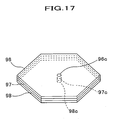
- Front mounting part 91 and rear mounting part 92 are plates each having approximately hexagonal shape viewing from upside, and three plates 93, 94, and 95 are connected to the ends of mounting portions 91 and 92 every other sides. Specifically, a prescribed distance is provided between plates 93, 94, and 95.
- Sliding members 96, 97, and 98 are plates each having approximately hexagonal shape viewing from upside, and engaging grooves 96a, 96b, and 96c, which are slidably engaged with guide member 99, are formed on sides opposite the sides connected to plates 93, 94, and 95, respectively.
- first sliding member 96, second sliding member 97, and third sliding member are provided so that they are overlapped with each other.
- iron piece IP to be attracted onto electromagnet EM which will be described later on, is fixed on a portion of front surface 96b of first sliding member 96 amongst three sliding members 96, 97, 98, and electromagnet EM which attracts iron piece by a magnetic force is fixed on a portion of rear surface 98b of third sliding member 98.
- electromagnet EM is controlled by controller 5 as described in the first embodiment.
- Guide member 99 possesses shaft portion 99a, in which engaging grooves 96a, 97a, and 98a of three sliding members 96, 97, and 98 are engaged, and flange portions 99b and 99c serving as a lock mechanism formed on both ends of shaft portion 99a.
- controller 5 does not allow current for running through two electromagnets EM, whereby no friction force is generated between three sliding members 96, 97, and 98.
- these three sliding members 96, 97, and 98 are slid to meet the deformation of three plates 93, 94, and 95.
- three plates 93, 94, and 95 are buckled in the primary mode with no restriction of three plates 93, 94, and 95 by iron piece IP and electromagnet EM.
- controller 5 supplies current to two electromagnets EM, EM, whereby iron piece IP is attracted onto electromagnets EM, EM to generate a friction force between three sliding members 96, 97, and 98.
- controller 5 supplies current to two electromagnets EM, EM, whereby iron piece IP is attracted onto electromagnets EM, EM to generate a friction force between three sliding members 96, 97, and 98.
- three plates 93, 94, and 95 is going to be deformed, sliding members 96, 97, and 98 are not slid and stay in those positions.
- three plates 93, 94, and 95 are restricted by three plates 93, 94, and 95 by iron piece IP and electromagnets EM, EM and are deformed in a tertiary deformation mode. It is noted that when current is supplied to only one of two electromagnet EM, EM, at this time, three plates 93, 94, and 95 are deformed in a secondary deformation mode as shown in FIG. 16B. Specifically, since various types of collision are considered in actual collision, the deformation mode can be switched to a secondary mode or a tertiary mode depending upon a degree of collision load.
- arrangement of three or more sets each comprising sliding members 96, 97, 98, iron piece IP, and electromagnet EM makes it possible to switch the state of buckling into a fourth or higher mode, and makes it possible to set a much higher buckling load.
- iron piece IP is used in the fourth embodiment, the present invention is not restricted thereto, and, for example, a permanent magnet may also be used. In this case, it is desirable to supply a type of current such that the permanent magnet and electromagnet EM are repulsed with each other at the time when plates 93, 94, and 95 are not restricted.
- restriction mechanism 100 is mounted. Restriction mechanism 100 is composed of fixing part 101 which is fixed onto sliding member 96, engaging part 102, which is mounted on fixing part 101 in a detachable manner, and coil spring 103, which is provided between these fixing part 101 and engaging part 102.
- concave portion 101a is formed on fixing part 101, and on concave portion 101a are formed electromagnet EM formed as an electromagnetic coil in a substantially cylindrical form and permanent magnet PM, which is provided inside electromagnet EM.
- electromagnet EM formed as an electromagnetic coil in a substantially cylindrical form
- permanent magnet PM is formed shorter than electromagnet EM
- pore 101b which can be engaged with pin 102a, which will be described later, is formed by inner circumferences of permanent magnet PM and electromagnet EM.
- engaging part 102 possesses pin 102a comprising a magnetic body, which is inserted in pores 96c, 97c, and 98c of sliding members 96, 97, and 98.
- pin 102a comprising a magnetic body, which is inserted in pores 96c, 97c, and 98c of sliding members 96, 97, and 98.
- restriction mechanism 100 operation of restriction mechanism 100 will now be described.
- An apparatus (M) for controlling the rigidity of vehicle body comprises a controller (5) for controlling a buckling form, which controls the buckling form by adding to a member (4) receiving a collision load a lateral force in the direction substantially perpendicular to the member (4).
Landscapes
- Engineering & Computer Science (AREA)
- Chemical & Material Sciences (AREA)
- Combustion & Propulsion (AREA)
- Transportation (AREA)
- Mechanical Engineering (AREA)
- Body Structure For Vehicles (AREA)
- Vehicle Body Suspensions (AREA)
Abstract
Description
- The present invention is directed to an apparatus for controlling the rigidity of vehicle body. In a vehicle having a configuration of absorbing shock due to collision, the apparatus of the present invention can control the rigidity of vehicle body so as to obtain an adequate reaction load depending upon the form of the collision.
- As the conventional apparatus for controlling the rigidity of vehicle body, the apparatus is disclosed in Japanese Patent Laid-Open Publication No. 11-291951, in which by means of piezo-electric actuators placed on side frames provided on right and left sides of the vehicle, a force against collision load or a force which promotes the collision load is applied to the side frames, whereby the rigidity of the side frames is switched in order to meet the different form of the collision. Specifically, the apparatus has a configuration that in the case of fully lapped collision where the entire surface of the vehicle body is collided as a whole, the rigidity of the frame is reduced, while in the case of the offset collision where the collision load is focused on one side frame, the rigidity of one of the side frames should be increased, whereby optimal shock-absorbing can be done in both collision forms.
- Due to the generation of the force against the collision load, i.e., the force directly receiving the collision load, through the piezo-electric actuators, the conventional configuration, however, requires a large amount of electric power for the actuation of the piezo-electric actuator. This enlarges the piezo-electric actuators themselves, and also leads to a large-sized battery for supplying power to the piezo-electric actuators.
- Recently, in addition to switching the rigidity depending upon the collision forms such as fully lapped collision and offset collision, it has been strongly desired to control the reaction force giving to a subject depending upon the size of the subject by switching the rigidity of the vehicle body.
- It is, therefore, an object of the present invention to provide an apparatus for controlling the rigidity of vehicle body, which can control the rigidity of the vehicle body, which varies depending upon the collision forms, with small outputting. Another object of the present invention is to provide an apparatus for controlling the rigidity of vehicle body, which can control a reaction force depending upon the subjects to be collided with the vehicle body.
- These and other objects can be attained by an apparatus for controlling the rigidity of vehicle body according to an exemplary aspect of the present invention, which comprises a controller for controlling a buckling form, which controls the buckling form by adding to a member receiving a collision load a lateral force in the direction substantially perpendicular to the member.
- The term "buckling form" used herein means to include primary deformation mode having one antinode, secondary deformation mode having two antinodes, and a multiple deformation mode having a plurality of antinodes. As a number of antinodes are increased, the rigidity of the member buckled at such a deformation mode is increased. In one aspect of the present invention, by restricting at least one portion, which becomes an antinode when the member is buckled, through a lateral force, the deformation mode is controlled to be switched into a multiple deformation mode.
- According to the apparatus of the present invention as described above, for example, side frames provided in the width direction of the vehicle are longitudinally divided and, the divided frames are connected to these members on which the apparatus of the present invention is provided. The apparatus of the present invention controls the buckling form by controlling a lateral force applied to a member receiving a collision load in the direction substantially perpendicular to the member.
- According to one preferred embodiment of the present invention, the member comprises hollow frame member, and the controller for controlling a buckling form comprises frame restrictors which are provided on at least one portion of said hollow member in the direction substantially perpendicular to the hollow member, and restrict the deformation of said frame member through the lateral force, and a restriction regulator which regulates the restriction state of said frame restrictors.
- The term "hollow member" used herein means member produced into a hollow form and examples include, but are not limited to, bumpers, frames, pillars, and cross-members. Also included in the hollow members are two plates provided so as to make a space, and four rods provided so as to make a space.
- According to another preferred embodiment of the present invention, said member comprises hollow frame member, and said controller for controlling a buckling form comprises frame restrictor which is inserted into said frame member in a movable manner, and restricts the deformation of said frame member through the lateral force, and a member for setting a position of said frame restrictor.
- According to still another preferred embodiment of the present invention, the apparatus according to the present invention also has at least one collision detector, and controls the lateral force depending upon the evaluation based on the output from said detector.
- In this embodiment, said controller for controlling a buckling form is preferably provided within a bumper, the collision detector preferably comprises at least one member selected from distance detector, speed sensor, and CCD camera. More preferably, the said collision detector comprises a plurality of distance sensors provided on a bumper.
- According to still another preferred embodiment of the present invention, he buckling form is assumed to be buckling due to a primary deformation mode and buckling due to a secondary deformation mode, and ratio of the length L of said member to the thickness t of said member "L/t" is set so that the difference between the buckling load at the primary deformation mode and that at the secondary deformation mode is equal to or near the maximum value.
- Preferred embodiments of the present invention will be described below, by way of example only, with reference to the accompanying drawings, in which:
- FIG. 1 is a plan view totally showing an apparatus for controlling the rigidity of vehicle body according to the present invention;
- FIG. 2 is a cross-sectional view showing a lateral force generator of the apparatus of FIG. 1;
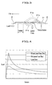
- FIG. 3 is a partially enlarged view showing the buckling state of plate of FIG. 2;
- FIG. 4 shows one characteristic of buckling load of the plate in one buckling form of FIG. 3;
- FIG. 5 shows another characteristic of buckling load of the plate in another buckling form of FIG. 3;
- FIG. 6 is a graph showing the relation between a collision form and a lateral force;
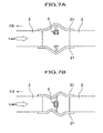
- FIG. 7 shows the actuation of the apparatus for controlling the rigidity of vehicle body of FIG. 1, wherein FIG. 7A shows the actuation of the apparatus in the case of fully lapped collision, and FIG. 7B shows the actuation of the apparatus in the case of offset collision;
- FIG. 8A is a side view showing the situation where the lateral force generator of FIG. 2 is provided on upper and lower portion of side frames at the bent portions, and FIG. 8B is a side view showing the situation where the lateral force generator of FIG. 2 is provided on a rear side of the crush box;
- FIG. 9 is a side and cross-sectional views side totally showing another embodiment of the lateral force generator of FIG. 2;
- FIG. 10A is a plan view totally showing still another embodiment of the lateral force generator of FIG. 2, FIG. 10B is a partially enlarged cross-sectional view showing the lateral force of FIG. 10A applied to a cross member, FIG. 10C is a partially enlarged cross-sectional view showing the situation where no lateral force is applied at the time of collision, and FIG. 10D is a partially enlarged cross-sectional view showing the situation where lateral force is applied at the time of collision;
- FIG. 11 is a perspective view showing a lateral force generator according to a second embodiment;
- FIG. 12 is a cross-sectional view of the lateral force generator, where FIG. 12A shows a normal state, FIG12B shows the state at fully lapped collision, and FIG. 12C shows the state of offset collision;
- FIG. 13A is a cross-sectional view showing a lateral force generator according to a third embodiment at a normal state and at the state of offset collision, and FIG. 13B is a cross-sectional view showing a lateral force generator according to a third embodiment at the state of fully lapped collision;
- FIG. 14 is a perspective view showing a lateral force generator according to a fourth embodiment;
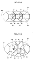
- FIG. 15A is a perspective -sectional view showing a lateral force generator according to a fourth embodiment at a normal state, and FIG. 15B is a perspective view showing a lateral force generator according to the fourth embodiment at the state of fully lapped collision or at the time of collision with a small subject;
- FIG. 16A is a perspective view showing a lateral force generator according to a fourth embodiment at the time of being buckled in a tertiary mode, and FIG. 16B is a perspective view showing a lateral force generator according to a fourth embodiment at the time of being buckled in a secondary mode;
- FIG. 17 is a drawing showing one example of a method of restricting sliding members;
- FIG. 18 is a side view showing one embodiment of a restriction mechanism in the fourth embodiment;
- FIG. 19 is a cross-sectional view of the restriction mechanism shown in FIG. 18; and
- FIG. 20 is a cross-sectional view showing the operation of the restriction mechanism shown in FIG. 18 in the state of not being restricted.
-
- First, the first embodiment of the apparatus for controlling the rigidity of vehicle body according to the present invention will be described referring to FIGs. 1 to 6.
- As shown in FIG. 1, apparatus M for controlling the rigidity of vehicle body according to the first embodiment of the present invention (hereinafter simply referred to as "apparatus") mainly comprises
lateral force generators left side frames vehicle 1, and a control device (controller) 5 provided oncenter frame 4 placed near the center ofvehicle 1. Further, apparatus M possesses distance sensors 61-66 (each serving as detection of collision) placed withinfront bumper 6. - As shown in FIG. 2,
lateral force generators 3 are placed in between a pair ofplates 21, 21 (hollow members) which bind side frames 2, 2 having been divided into two pieces in the longitudinal direction to each other. Each oflateral force generators 3 mainly comprises supportingrods 31, 31 (frame restrictors),permanent magnet 32 provided on the tip of one of supportingrods rods controller 5, a lateral force (absorbing force) substantially perpendicular toside frame 2 andplate 21 is controlled. - As shown in FIG. 3,
plate 21 buckles in a primary deformation mode having oneantinode 21a, when a collision load is inputted at a time which a lateral force greater than a given value is not applied fromlateral force generator 3.Plate 21 buckles in a secondary (multiple) deformation mode having two (multiple)antinodes lateral force generator 3. Specifically, the buckling form of thisplate 21 can be switched from the primary deformation mode into the secondary deformation mode by restricting substantially the central portion of theantinode 21a of the primary deformation mode (the point of the action) by means of the lateral force fromlateral force generator 3. - As shown in FIG. 4, there is a characteristic that the load (buckling load) against collision load in the case of buckling in the secondary deformation mode is higher than that in the case of the buckling in the primary deformation mode. Particularly, comparing the peak values generated immediately after collision load is inputted, the difference between two modes is significant, which is approximately twice. From this, it can be understood that the rigidity can be controlled over a wide range by switching the deformation mode from the primary deformation mode into the secondary deformation mode or vice versa. The lateral force by
lateral force generator 3 is very small in comparison with these loads. The artisan will prove that by applying only such a very small lateral force, the primary deformation mode can be switched into the secondary deformation mode, whose load is twice that of the primary deformation mode. Apparatus M makes use of such a buckling characteristic possessed byplate 21, and controls a small lateral force generated fromlateral force generator 3 bycontroller 5, whereby the buckling mode ofplate 21 is controlled to control the rigidity thereof within a wide range. - Furthermore, as shown in FIG. 5, the buckling mode of
plate 21 has a specific relation to the ratio of length L to thickness t of plate 21 (herein after abbreviated as "L/t ratio"). Specifically, both in the primary deformation mode and the secondary deformation mode, there is a tendency that the buckling load is increased as an L/t ratio becomes small, and the buckling load is decreased as it becomes large. Also, both the primary deformation mode and the secondary deformation modes exhibit plastic buckling at an L/t ratio lower than a given value, and exhibit elastic buckling at an L/t ratio greater than a given value. Here it should be noted that the buckling load in the plastic buckling would be calculated according to Johnson's equation, whereas the buckling load in the elastic buckling would be calculated according to Euler's equation. The difference between the buckling loads of the secondary deformation mode and the primary deformation mode becomes maximum around a shaded portion depicted on FIG. 5 (where the buckling load becomes plastic buckling in the secondary deformation mode and it becomes elastic buckling in the primary deformation mode).Plate 21 used in this embodiment has such an L/t ratio to have the maximum difference and, thus, the rigidity range ofplate 21 can be switched over a wide range. The L/t ratio having the maximum difference depends upon the material to be used. For example, the L/t ratio having the maximum difference is 50 for aluminum and 100 for iron. - It should be noted that the use of
plate 21 having an L/t ratio with the maximum difference in buckling load is not essential in the present invention, and the L/t ratio may be freely selected. For example,plate 21 used may have an L/t ratio slightly smaller than that shown as shaded portion in FIG. 5. In this case, although the difference in the buckling load between the secondary deformation mode and the primary deformation mode is slightly smaller thanplate 21 having the L/t ratio within the shaded portion, the buckling loads themselves may be advantageously increased. - As shown in FIG. 1,
controller 5 detects the collision form on the basis of the outputs from distance sensors 61-66, and controls the current supplied to electromagnet 33 oflateral force generator 3 depending upon the detected collision form. Distance sensors 61-66 detect the collision form. Specifically, they detect the distance to the collided subject using laser or ultrasonic wave. If the outputted values from all of distance sensors 61-66 are judged to be lower than a given value bycontroller 5, thecontroller 5 judges that the collision form is fully lapped collision. If the outputted value from at least one distance sensor 61-63 at the right side of the vehicle or at least one distance sensor 64-66 is judged to be lower than a given value bycontroller 5, thecontroller 5 judges that the collision form is offset collision. As shown in FIG. 6, when judged to be the fully lapped collision,controller 5 gives current lower than that running throughelectromagnet 33 at a usual state toelectromagnet 33. When judged to be the offset collision,controller 5 gives electromagnet a current required for switching the mode into the secondary deformation mode. By controlling the current as described above, the pair ofplates plate 21 becomes easily buckled in the primary deformation mode. At the time of offset collision, the lateral force becomes higher than the given value, whereby eachplate 21 is buckled in the secondary deformation mode. - The control of the current given to
electromagnet 31 should not be restricted to the control as described, and any control may be performed. For example, whencontroller 5 judged to be the fully lapped collision, controller may giveelectromagnet 33 current in the reverse direction to that at the usual time and at the time of the offset collision. In this case, since a lateral force acted on the pair ofplates plates controller 5 gives current to electromagnet 33 only when it judges to be the offset collision. Specifically, thecontroller 5 may control ON/OFF of electromagnet to switch the mode, i.e., from the primary deformation mode to the secondary deformation mode or vice versa. - Next, the operation of apparatus M will be described by referring to FIGs. 1, 2, and 7.
- First, referring to FIG. 1, the case will be described where
vehicle 1 is collided in a fully lapped manner. - If
vehicle 1 will be collided with a subject in a fully lapped manner, the signals detected from distance sensors 61-66 are outputted tocontroller 5.Controller 5 judges that all the outputted values are less than a given value and then judges to be fully lapped collision.Controller 5, which has judged to be fully lapped collision as described above, decreases the current running through electromagnet 33 (see FIG. 2) to thereby make the lateral force generated fromlateral force generator 3 smaller than the usual case. Upon the fully lapped collision ofvehicle 1, each ofplate 21 is buckled in the primary deformation mode in the direction thatplates - Next, referring to FIG. 1, the case will be described where
vehicle 1 is collided in an offset manner. Ifvehicle 1 will be collided with a subject in an offset manner, for example at the right side, the signals detected from distance sensors 61-63 at the right side are outputted tocontroller 5.Controller 5 then judges that the outputted values are lower than a given value, and judges to be offset collision.Controller 5, which has judged to be offset collision as described above, increases the current running through electromagnet 33 (see FIG. 2) to thereby make the lateral force generated fromlateral force generator 3 larger than the usual case. Upon the offset collision ofvehicle 1,plates - As described above, the following advantages can be exhibited according to the first embodiment of the present invention:
- Since apparatus M controls a lateral force which is substantially perpendicular to the member (in this case,
side frame 2 and plate 21), i.e., only restricts a part ofantinode 21a in the primary deformation mode, whereby the rigidity ofplate 21 can be controlled, apparatus M can control the rigidity of side frames only by a force smaller than the force against the collision load as in the prior art. Consequently, the size of the apparatus M and battery or such for supplying power to the apparatus M can be decreased. - Since the lateral force is controlled on the basis of the signals indicating the collision form detected from distance sensors 61-66, the rigidity of
plate 21 can be freely controlled depending upon the collision form. - While the collision form is judged only based on the outputted valued from distance sensors 61-66, the present invention is not restricted thereto. For example, speed sensor or such may be provided in addition to these distance sensors. In the configuration where speed sensor is provided, as
lateral force generator 3 is not controlled at the time of drivingvehicle 1 at a low speed as in the case of putting the vehicle in a garage, the cost for requiring the power consumption can be reduced. Also, sensor may be configured so that an image is inputted from CCD camera or other image capturing means to judge the collision form and whether or not vehicle is collided. - The pair of
plates lateral force generator 3 or may be disposed on anywhere. For example, they can be placed onside frame 2 at the vertically bent portion as shown in FIG. 8A (the position according to the first embodiment) , or on a portion behindcrush box 8 for absorbing the collision load as shown in FIG. 8B. - While
plate 21 is used as the subject to control the rigidity by apparatus M, the subject is not restricted thereto. For example, the rigidity of the panel of vehicle body can be directly controlled. For example, as shown in FIG. 9, the subj ect may be provided withinfront bumper 6, within crush box B,side frame 2 or in betweenfloor frame 22 formed at portion one step below theside frame 2 andfloor panel 23 which is conjugated withfloor frame 22. This makes it possible to control the crushing ability offront bumper 6 and that of crush box B, as well as to control the rigidity of side frame. Also, as shown in FIGs. 10A and 10B,lateral force generator 3 may be provided in between cross member C andfloor panel 23, which is conjugated with cross member C. Buckling of thislateral force generator 3 in the primary or secondary deformation mode can control the rigidity of floor panel 23 (see Figs. 10C and 10D). In the case wherelateral force generator 3 is provided in between cross member C andfloor panel 23, since the rigidity of cross member C is higher thanfloor panel 23, thislateral force generator 3 is used only for the purpose of controlling the rigidity offloor panel 23. Other places for providinglateral force generator 3 include pillar and rear bumper. - Also, as shown in FIG. 9, in the case where
lateral force generator 3 is provided in betweenupper wall 6a andlower wall 6b making upfront bumper 6, distance sensors 61-66 described in the first embodiment is used for detecting a subject, whereby the rigidity offront bumper 6 can be changed depending upon the size of the subject. Specifically, for example, only two of six distance sensors 61-66 output signals,controller 5 judges that the subject is small and makes the rigidity of front bumper small. Conversely, if three or more of distance sensors 61-66 output signals,controller 5 judges that the subject is large and makes the rigidity of front bumper large. For this reason, for example, if the vehicle body is collided with an electric or telephone pole or such, which is a small subject, then the impact to the pole or such can be reduced. Conversely, if the vehicle body is collided with a big subject such as a big car, the rigidity of the vehicle body can be enhanced. It is also possible to predict the collision and then control the rigidity of vehicle body. - A second embodiment of the apparatus for controlling the rigidity of vehicle body according to the present invention will now be described. The second embodiment is a variation of the first embodiment in which
lateral force generator 3 in the first embodiment is modified. Consequently, the same parts and elements as those in the first embodiment are referred to the same numbers or symbols and the detailed description thereof will be omitted. - As shown in FIG. 11,
lateral force generator 7 according to this embodiment mainly comprises fourrods 71, ... (hollow frames), which bind longitudinally divided side frames 2, and ring 72 (for frame restriction), which is slidably fitted to theserods 71, .... Regulation lever 73 (for setting the restriction position) is rotatably fit to the vehicle body (not shown).Regulation lever 73 rotates only when a signal indicates offset collision outputted fromcontroller 5 to release the regulation.Stopper 74 for regulating the movement of each rod 71 (which sets the restriction position) is provided on an approximately center of eachrod 71. - Next, the operation of apparatus M will be described by referring to FIG. 12.
- As shown in FIG. 12A, at a normal driving state,
ring 72 whose forward movement is always regulated byregulation lever 73, remains unmoved even if inertia is acted on ring to go forwards due to stepping-in the break etc. At the time of collision, when the collision form detected by distance sensors 61-66 is fully lapped collision, as shown in FIG. 12B, in the state whereregulation lever 73 fastensring 72 at a rear side ofrod 71,rod 71 is buckled in the primary mode. When the collision form is offset collision, as shown in FIG. 12C,ring 72, from which the regulation byregulation lever 73 is released, moves forward due to the inertia generated at the time of the collision, and stops at the portion ofstopper 74. As described above,ring 72 is positioned at approximately center ofrod 71, wherebyrod 71, whose central portion is restricted byring 72, is buckled in the secondary mode. - As described above, according to the second embodiment of the present invention, the following advantages can be obtained.
- In the second embodiment, which uses inertia acted upon
ring 72 at the time of collision, only the control, which can revolvesregulation lever 73, is required only in the case of offset collision. Accordingly, cost due to power consumption can be reduced in comparison with the first embodiment. - A third embodiment of the apparatus for controlling the rigidity of vehicle body according to the present invention will now be described. The third embodiment is a variation of the first embodiment in which
lateral force generator 3 in the first embodiment is modified. Consequently, the same parts and elements as those in the first embodiment are referred to the same numbers or symbols and the detailed description thereof will be omitted. - As shown in FIG. 13A,
lateral force generator 8 is provided in between a pair ofplates lateral force generator 8 mainly comprises supportingplates plates elastic alloy 82 disposed between these supportingplates switch 83. Superelastic alloy 82 serves as a plate spring, one end of which is fixed on the frontside supporting plate 82, and the other end being communicated withstopper 83a possessed bydrive switch 83 in the state that center of superelastic alloy 82 is bent.Stopper 83a has a configuration that it can freely move forwards and backwards bysolenoid 83b, which generates a magnetic power upon supplying power, and it moves backwards only whencontroller 5 outputs a signal indicating fully lapped collision (see FIG. 13B). Connectingpin 84 for connecting two supportingplates elastic alloy 82 at the center thereof. Connectingpin 84 is tilted relative to the rearside supporting plate 81 so that the axis direction thereof is along with the direction that connectingpin 84 comes off. - Next, the operation of apparatus M will be described by referring to FIG. 13.
- As shown in FIG. 13A, at the time of a normal driving state, the other end of super
elastic alloy 82 is suppressed bystopper 83a, whereby two supportingplates pin 84. In the case where the collision form is offset collision,lateral force generator 8 keeps the as is state, whereby the center portion of eachplate 21 is restricted to buckle eachplate 21 at the secondary deformation mode. In the case where the collision form is fully lapped collision, as shown in FIG. 13B,stopper 83a moves backwards, whereby superelastic alloy 82, which has been suppressed in the bent state, is returned into its original state and connectingpin 84 comes off. For this reason, the center portion of eachplate 21 is not restricted and, thus, eachplate 21 is buckled in the primary mode. - As described above, according to the third embodiment of the present invention, the following advantages can be obtained.
- In the third embodiment, which uses the force that super
elastic alloy 82 is returned into the original state, a current in a given direction is run throughsolenoid 83 only in the case of fully lapped collision. Accordingly, cost due to power consumption can be reduced in comparison with the first embodiment. - A fourth embodiment of the apparatus for controlling the rigidity of vehicle body according to the present invention will now be described. The fourth embodiment is a variation of the first embodiment in which
lateral force generator 3 in the first embodiment is modified. Consequently, the same parts and elements as those in the first embodiment are referred to the same numbers or symbols and the detailed description thereof will be omitted. - As shown in FIG. 14,
lateral force generator 9 is provided in between a pair of vertically divided side frames 2, as in the first embodiment.Lateral force generator 9 is mainly composed of frontside mounting portion 91, which is connected tofront side frame 2, rearside mounting portion 92, which is connected torear side frame 2,first plate 93 andsecond plate 94, both ends of which are connected to these mountingportions third plate 95. Furthermore,lateral force generator 9 has a pair of first slidingmembers members members first plate 93,second plate 94, andthird plate 95, respectively, as well asguide members members first plate 93 in the state where a part offirst plate 93 is broken. -
Front mounting part 91 andrear mounting part 92 are plates each having approximately hexagonal shape viewing from upside, and threeplates portions plates - Sliding
members grooves guide member 99, are formed on sides opposite the sides connected toplates plate front mounting part 91 andrear mounting part 92, from the front side to the rear side, first slidingmember 96, second slidingmember 97, and third sliding member are provided so that they are overlapped with each other. - Furthermore, iron piece IP to be attracted onto electromagnet EM, which will be described later on, is fixed on a portion of
front surface 96b of first slidingmember 96 amongst three slidingmembers rear surface 98b of third slidingmember 98. When iron piece IP is attracted onto electromagnet EM, a friction force is generated between three slidingmembers plates controller 5 as described in the first embodiment. -
Guide member 99 possessesshaft portion 99a, in which engaginggrooves members flange portions 99b and 99c serving as a lock mechanism formed on both ends ofshaft portion 99a. - Next, the operation of apparatus M having
lateral force generator 9 just mentioned will be described by referring to FIG. 15. - As shown in FIG. 15A, at a normal driving state, since no collision load is inputted to
plates members controller 5 does not allow current for running through two electromagnets EM, whereby no friction force is generated between three slidingmembers members plates plates plates - Also, as shown in FIG. 16A, in the case where a high buckling load is required such as in the case of offset collision or in the case of being collided with a big subject (as in the case where the subject is a large-sized car or such),
controller 5 supplies current to two electromagnets EM, EM, whereby iron piece IP is attracted onto electromagnets EM, EM to generate a friction force between three slidingmembers plates members plates plates plates members - As described above, the following advantages can be obtained according to the fourth embodiment of the present invention.
- Since side frames 2, 2, which are divided into two portions, are connected to three
plates plates plates plates - It should be noted that while iron piece IP is used in the fourth embodiment, the present invention is not restricted thereto, and, for example, a permanent magnet may also be used. In this case, it is desirable to supply a type of current such that the permanent magnet and electromagnet EM are repulsed with each other at the time when
plates - As another method for restricting a configuration can be considered that sliding
members pores members restriction mechanism 100 as shown in FIG. 18 is mounted.Restriction mechanism 100 is composed of fixingpart 101 which is fixed onto slidingmember 96, engagingpart 102, which is mounted on fixingpart 101 in a detachable manner, andcoil spring 103, which is provided between these fixingpart 101 andengaging part 102. - As shown in FIG. 19,
concave portion 101a is formed on fixingpart 101, and onconcave portion 101a are formed electromagnet EM formed as an electromagnetic coil in a substantially cylindrical form and permanent magnet PM, which is provided inside electromagnet EM. When permanent magnet PM is formed shorter than electromagnet EM,pore 101b, which can be engaged withpin 102a, which will be described later, is formed by inner circumferences of permanent magnet PM and electromagnet EM. - As shown in FIG. 18, engaging
part 102 possessespin 102a comprising a magnetic body, which is inserted inpores members pin 102a onto permanent magnet PM at a normal state,coil spring 103 placed aroundpin 102a always applies a bias force to slidingmembers - Subsequently, operation of
restriction mechanism 100 will now be described. - As shown in FIG. 20, at a normal state or when a high buckling load is required, by maintaining the state where
pin 102a is attracted onto permanent magnet PM, slidingmembers coil spring 103 is returned to unlockpin 102a frompores members - An apparatus (M) for controlling the rigidity of vehicle body according to the present invention comprises a controller (5) for controlling a buckling form, which controls the buckling form by adding to a member (4) receiving a collision load a lateral force in the direction substantially perpendicular to the member (4).
Claims (8)
- An apparatus (M) for controlling the rigidity of vehicle body, which comprises:a controller (5) for controlling a buckling form, which controls the buckling form by adding to a member (4) receiving a collision load a lateral force in the direction substantially perpendicular to said member (4).
- The apparatus (M) as claimed in Claim 1, wherein said member (4) comprises hollow frame member (21), and
said controller (5) for controlling a buckling form comprises frame restrictors (31) which are provided on at least one portion of said hollow member (21) in the direction substantially perpendicular to said hollow member (21) , and restrict the deformation of said frame member (4) through the lateral force, and a restriction regulator (33) which regulates the restriction state of said frame restrictors (31). - The apparatus (M) as claimed in Claim 1, wherein said member (4) comprises hollow frame member (71), and
said controller (5) for controlling a buckling form comprises frame restrictor (72) which is inserted into said frame member (71) in a movable manner, and restricts the deformation of said frame member (71) through the lateral force, and a member (73) for setting a position of said frame restrictor (72). - The apparatus (M) as claimed in any one of Claims 1 to 3, which further comprises at least one collision detector, and controls the lateral force depending upon the evaluation based on the output from said detector.
- The apparatus (M) as claimed in Claim 4, wherein said controller (5) for controlling a buckling form is provided within a bumper.
- The apparatus (M) as claimed in Claim 4, wherein said collision detector comprises at least one member selected from distance detector, speed sensor, and CCD camera.
- The apparatus (M) as claimed in Claim 4, wherein said collision detector comprises a plurality of distance sensors (61-66) provided on a bumper (6).
- The apparatus (M) as claimed in Claim 1, wherein the buckling form is assumed to be buckling due to a primary deformation mode and buckling due to a secondary deformation mode, and ratio of the length L of said member to the thickness t of said member "L/t" is set so that the difference between the buckling load at the primary deformation mode and that at the secondary deformation mode is equal to or near the maximum value.
Applications Claiming Priority (2)
| Application Number | Priority Date | Filing Date | Title |
|---|---|---|---|
| US10/621,458 US7232002B2 (en) | 2003-07-18 | 2003-07-18 | Apparatus for controlling rigidity of vehicle body |
| US621458 | 2003-07-18 |
Publications (3)
| Publication Number | Publication Date |
|---|---|
| EP1498343A2 true EP1498343A2 (en) | 2005-01-19 |
| EP1498343A3 EP1498343A3 (en) | 2005-01-26 |
| EP1498343B1 EP1498343B1 (en) | 2008-03-12 |
Family
ID=33477114
Family Applications (1)
| Application Number | Title | Priority Date | Filing Date |
|---|---|---|---|
| EP04015998A Expired - Lifetime EP1498343B1 (en) | 2003-07-18 | 2004-07-07 | Apparatus for controlling rigidity of vehicle body |
Country Status (4)
| Country | Link |
|---|---|
| US (1) | US7232002B2 (en) |
| EP (1) | EP1498343B1 (en) |
| JP (1) | JP3976270B2 (en) |
| DE (1) | DE602004012354T2 (en) |
Cited By (6)
| Publication number | Priority date | Publication date | Assignee | Title |
|---|---|---|---|---|
| EP1600334A1 (en) * | 2004-05-27 | 2005-11-30 | Honda Motor Co., Ltd. | Apparatus for adjusting rigidity of vehicle body |
| WO2007137664A1 (en) * | 2006-05-26 | 2007-12-06 | Daimler Ag | Motor vehicle bodyshell structure for reducing or preventing lateral sliding of the motor vehicle bodyshell structure in the event of a crash |
| WO2014000981A1 (en) * | 2012-06-25 | 2014-01-03 | Robert Bosch Gmbh | Device for changing the rigidity of a vehicle, method for activating a device for changing the rigidity of a vehicle, and control unit |
| WO2014137252A1 (en) * | 2013-03-04 | 2014-09-12 | Autoliv Development Ab | A safety arrangement for a vehicle |
| DE102020113627A1 (en) | 2020-05-20 | 2021-11-25 | Bayerische Motoren Werke Aktiengesellschaft | Front end structure for a passenger car as well as passenger cars |
| US12083977B1 (en) * | 2022-07-29 | 2024-09-10 | Zoox, Inc. | Active buckling frame rail |
Families Citing this family (25)
| Publication number | Priority date | Publication date | Assignee | Title |
|---|---|---|---|---|
| AT412550B (en) * | 2003-06-24 | 2005-04-25 | Voestalpine Stahl Gmbh | CARRIER FOR A VEHICLE BODY |
| JP4323922B2 (en) * | 2003-10-23 | 2009-09-02 | 本田技研工業株式会社 | Body rigidity adjustment device |
| JP4268011B2 (en) * | 2003-10-23 | 2009-05-27 | 本田技研工業株式会社 | Body rigidity adjustment device |
| JP4649849B2 (en) * | 2004-03-02 | 2011-03-16 | トヨタ自動車株式会社 | Storage mechanism mounting structure |
| US8256829B2 (en) * | 2004-04-02 | 2012-09-04 | GM Global Technology Operations LLC | Active material inserts for use with hollow structures |
| GB2422645B (en) * | 2005-02-01 | 2009-05-13 | Autoliv Dev | Improvements in or relating to a safety arrangement |
| JP5141026B2 (en) * | 2006-02-27 | 2013-02-13 | トヨタ自動車株式会社 | In-vehicle structure of power storage pack |
| JP4792303B2 (en) * | 2006-03-13 | 2011-10-12 | 本田技研工業株式会社 | Shock absorber for vehicle |
| DE602006012128D1 (en) * | 2006-06-14 | 2010-03-25 | Autoliv Dev | VEHICLE STRUCTURE ARRANGEMENT SUBMITTED WITH PRESSURIZABLE GAIN ELEMENT |
| EP1977956B1 (en) * | 2007-04-03 | 2012-08-29 | Nissan Motor Co., Ltd. | Installation structure and method of vehicular suspension |
| JP5084623B2 (en) * | 2007-09-27 | 2012-11-28 | 本田技研工業株式会社 | Vehicle body strength adjusting device |
| DE102008062501A1 (en) * | 2008-12-16 | 2010-06-17 | Daimler Ag | Energy absorption device for e.g. lorry, has set of walls cooperating with another set of walls under formation of tribological pairing during deformation, and chamber deformed under deformation during force application caused by accident |
| DE102009000122A1 (en) * | 2009-01-09 | 2010-07-15 | Robert Bosch Gmbh | Method and control unit for adapting a triggering information of a restraint system |
| US8660756B2 (en) * | 2010-01-11 | 2014-02-25 | Honda Motor Co., Ltd. | Collision mitigation system |
| DE102010048102A1 (en) * | 2010-10-09 | 2012-04-12 | Audi Ag | Vehicle with a crash energy absorbable traction battery |
| DE102011078029B3 (en) * | 2011-06-24 | 2012-10-31 | Robert Bosch Gmbh | Device for changing rigidity of cross beam of motor car, has stiffening element movably arranged at cross beam and producing rigidities of cross beam in positions, and actuator moving stiffening element between positions |
| JP5714126B2 (en) * | 2011-11-30 | 2015-05-07 | 本田技研工業株式会社 | Electric vehicle |
| DE102012221193B4 (en) * | 2012-11-20 | 2023-03-16 | Bayerische Motoren Werke Aktiengesellschaft | Motor vehicle body designed for a small overlap collision |
| JP6077402B2 (en) * | 2013-06-28 | 2017-02-08 | 富士重工業株式会社 | Body front structure |
| US10336397B2 (en) | 2014-12-29 | 2019-07-02 | Peter Tristan Ridet | System and method for dynamic motorcycle frame |
| DE102016110662A1 (en) * | 2016-06-09 | 2017-12-14 | Eto Magnetic Gmbh | Damping device and method with a damping device |
| JP6805999B2 (en) * | 2017-08-10 | 2020-12-23 | 豊田合成株式会社 | Variable rigidity structure of vehicle support |
| CN115431916B (en) * | 2022-10-09 | 2024-09-06 | 吉林大学 | Active energy absorbing structure capable of withstanding oblique impact and control method thereof |
| CN115416603B (en) * | 2022-10-09 | 2024-09-06 | 吉林大学 | Automobile pre-collision device and control method capable of actively controlling crushing and deformation of energy absorption box |
| CN117182970A (en) * | 2023-10-18 | 2023-12-08 | 中国三峡建工(集团)有限公司 | A kind of stability and anti-shake structure for inspection robot |
Citations (1)
| Publication number | Priority date | Publication date | Assignee | Title |
|---|---|---|---|---|
| JPH11291951A (en) | 1998-04-03 | 1999-10-26 | Honda Motor Co Ltd | Body rigidity control device |
Family Cites Families (15)
| Publication number | Priority date | Publication date | Assignee | Title |
|---|---|---|---|---|
| US3848914A (en) * | 1971-12-15 | 1974-11-19 | Sperry Rand Corp | Motor shiftable shock absorbing bumper |
| DE2364300A1 (en) * | 1973-12-22 | 1975-06-26 | Porsche Ag | DEVICE FOR ENERGY ABSORPTION FOR VEHICLES, IN PARTICULAR MOTOR VEHICLES |
| US4518183A (en) * | 1984-02-27 | 1985-05-21 | Lee Joseph K | Extendible safety impact bags for vehicles |
| US5106137A (en) * | 1991-06-28 | 1992-04-21 | Davidson Textron Inc. | Vehicle bumper with combination foam and air bag energy absorber |
| US5141279A (en) * | 1991-09-23 | 1992-08-25 | Davidson Textron Inc. | Side impact protection apparatus |
| US5460421A (en) * | 1994-05-31 | 1995-10-24 | Chrysler Corporation | Active impact column |
| US5845937A (en) * | 1997-02-10 | 1998-12-08 | Morton International, Inc. | Structural assembly |
| US6193303B1 (en) * | 1998-04-03 | 2001-02-27 | Honda Giken Kogyo Kabushiki Kaisha | Control device for controlling rigidity and deformation of car body |
| WO2000002751A1 (en) * | 1998-07-09 | 2000-01-20 | Giat Industries | Bumper equipped with shock absorbing means |
| JP2000053020A (en) | 1998-08-17 | 2000-02-22 | Honda Motor Co Ltd | Car body structure |
| US6113178A (en) * | 1998-08-31 | 2000-09-05 | Trw Vehicle Safety Systems Inc. | Vehicle energy absorption apparatus |
| SE514790C2 (en) * | 1999-09-15 | 2001-04-23 | Saab Ab | Method and apparatus for actively controlling deformation patterns for structural elements |
| SE522302C2 (en) * | 2000-05-05 | 2004-01-27 | Elaion Ab | Device for vehicles, including deformation beams, and a method for adapting a vehicle's energy absorption |
| US6364399B1 (en) * | 2000-08-10 | 2002-04-02 | Daimlerchrysler Corporation | Pressurized structural member of a motor vehicle frame |
| EP1331161B1 (en) * | 2002-01-16 | 2009-06-10 | Nissan Motor Co., Ltd. | Reinforcing structure for body frame of vehicle |
-
2003
- 2003-07-18 US US10/621,458 patent/US7232002B2/en not_active Expired - Fee Related
-
2004
- 2004-01-26 JP JP2004017008A patent/JP3976270B2/en not_active Expired - Lifetime
- 2004-07-07 EP EP04015998A patent/EP1498343B1/en not_active Expired - Lifetime
- 2004-07-07 DE DE602004012354T patent/DE602004012354T2/en not_active Expired - Lifetime
Patent Citations (1)
| Publication number | Priority date | Publication date | Assignee | Title |
|---|---|---|---|---|
| JPH11291951A (en) | 1998-04-03 | 1999-10-26 | Honda Motor Co Ltd | Body rigidity control device |
Cited By (8)
| Publication number | Priority date | Publication date | Assignee | Title |
|---|---|---|---|---|
| EP1600334A1 (en) * | 2004-05-27 | 2005-11-30 | Honda Motor Co., Ltd. | Apparatus for adjusting rigidity of vehicle body |
| US7195305B2 (en) | 2004-05-27 | 2007-03-27 | Honda Motor Co., Ltd. | Apparatus for adjusting rigidity of vehicle body |
| WO2007137664A1 (en) * | 2006-05-26 | 2007-12-06 | Daimler Ag | Motor vehicle bodyshell structure for reducing or preventing lateral sliding of the motor vehicle bodyshell structure in the event of a crash |
| WO2014000981A1 (en) * | 2012-06-25 | 2014-01-03 | Robert Bosch Gmbh | Device for changing the rigidity of a vehicle, method for activating a device for changing the rigidity of a vehicle, and control unit |
| WO2014137252A1 (en) * | 2013-03-04 | 2014-09-12 | Autoliv Development Ab | A safety arrangement for a vehicle |
| DE102020113627A1 (en) | 2020-05-20 | 2021-11-25 | Bayerische Motoren Werke Aktiengesellschaft | Front end structure for a passenger car as well as passenger cars |
| DE102020113627B4 (en) | 2020-05-20 | 2026-02-26 | Bayerische Motoren Werke Aktiengesellschaft | Front structure for a passenger car as well as passenger cars |
| US12083977B1 (en) * | 2022-07-29 | 2024-09-10 | Zoox, Inc. | Active buckling frame rail |
Also Published As
| Publication number | Publication date |
|---|---|
| DE602004012354D1 (en) | 2008-04-24 |
| JP2005035519A (en) | 2005-02-10 |
| EP1498343B1 (en) | 2008-03-12 |
| US7232002B2 (en) | 2007-06-19 |
| EP1498343A3 (en) | 2005-01-26 |
| US20050012317A1 (en) | 2005-01-20 |
| JP3976270B2 (en) | 2007-09-12 |
| DE602004012354T2 (en) | 2009-03-12 |
Similar Documents
| Publication | Publication Date | Title |
|---|---|---|
| EP1498343B1 (en) | Apparatus for controlling rigidity of vehicle body | |
| US7090288B2 (en) | Apparatus for controlling stiffness of a vehicle body | |
| US10882489B2 (en) | Vehicle seatbelt device | |
| JP2019214378A (en) | Morphing energy absorber system for vehicle assembly | |
| EP1899198B1 (en) | Releasable holding mechanism and method of use | |
| JP2006008108A (en) | Body strength control device | |
| JP4217141B2 (en) | Body rigidity adjustment device | |
| KR20060048569A (en) | Energy Absorption Steering | |
| JP3516588B2 (en) | Body rigidity control device | |
| JP2005280654A (en) | Shock absorbing steering device | |
| EP1464561A2 (en) | Controlled energy absorbtion steering column | |
| JP2006008106A (en) | Body strength adjustment device | |
| JP2008207571A (en) | Deck board | |
| JP2018034545A (en) | Mobile device | |
| KR101956264B1 (en) | Extensible apparatus for seat cushion in vehicle | |
| US20050087972A1 (en) | Apparatus for controlling vehicle body rigidity | |
| CN117584824A (en) | Energy absorbing device for vehicle seats | |
| JPH04110253A (en) | Automatic seat belt device | |
| JP2013166405A (en) | Collision load reducing mechanism | |
| JP5816724B2 (en) | Vehicle hood moving device | |
| JP2006007807A (en) | Body rigidity control device | |
| JP4524899B2 (en) | Shock absorbing steering column device | |
| JP5803841B2 (en) | Vehicle feeding device | |
| JP2013032061A (en) | Seat belt device | |
| JP5616370B2 (en) | Vehicle hood moving device |
Legal Events
| Date | Code | Title | Description |
|---|---|---|---|
| PUAI | Public reference made under article 153(3) epc to a published international application that has entered the european phase |
Free format text: ORIGINAL CODE: 0009012 |
|
| PUAL | Search report despatched |
Free format text: ORIGINAL CODE: 0009013 |
|
| AK | Designated contracting states |
Kind code of ref document: A2 Designated state(s): AT BE BG CH CY CZ DE DK EE ES FI FR GB GR HU IE IT LI LU MC NL PL PT RO SE SI SK TR |
|
| AX | Request for extension of the european patent |
Extension state: AL HR LT LV MK |
|
| AK | Designated contracting states |
Kind code of ref document: A3 Designated state(s): AT BE BG CH CY CZ DE DK EE ES FI FR GB GR HU IE IT LI LU MC NL PL PT RO SE SI SK TR |
|
| AX | Request for extension of the european patent |
Extension state: AL HR LT LV MK |
|
| 17P | Request for examination filed |
Effective date: 20050218 |
|
| AKX | Designation fees paid |
Designated state(s): DE SE |
|
| 17Q | First examination report despatched |
Effective date: 20070604 |
|
| GRAP | Despatch of communication of intention to grant a patent |
Free format text: ORIGINAL CODE: EPIDOSNIGR1 |
|
| GRAS | Grant fee paid |
Free format text: ORIGINAL CODE: EPIDOSNIGR3 |
|
| GRAA | (expected) grant |
Free format text: ORIGINAL CODE: 0009210 |
|
| AK | Designated contracting states |
Kind code of ref document: B1 Designated state(s): DE SE |
|
| REF | Corresponds to: |
Ref document number: 602004012354 Country of ref document: DE Date of ref document: 20080424 Kind code of ref document: P |
|
| PLBE | No opposition filed within time limit |
Free format text: ORIGINAL CODE: 0009261 |
|
| STAA | Information on the status of an ep patent application or granted ep patent |
Free format text: STATUS: NO OPPOSITION FILED WITHIN TIME LIMIT |
|
| 26N | No opposition filed |
Effective date: 20081215 |
|
| PGFP | Annual fee paid to national office [announced via postgrant information from national office to epo] |
Ref country code: SE Payment date: 20090708 Year of fee payment: 6 |
|
| PGFP | Annual fee paid to national office [announced via postgrant information from national office to epo] |
Ref country code: DE Payment date: 20100630 Year of fee payment: 7 |
|
| PG25 | Lapsed in a contracting state [announced via postgrant information from national office to epo] |
Ref country code: DE Free format text: LAPSE BECAUSE OF NON-PAYMENT OF DUE FEES Effective date: 20120201 |
|
| REG | Reference to a national code |
Ref country code: DE Ref legal event code: R119 Ref document number: 602004012354 Country of ref document: DE Effective date: 20120201 |
|
| PG25 | Lapsed in a contracting state [announced via postgrant information from national office to epo] |
Ref country code: SE Free format text: LAPSE BECAUSE OF NON-PAYMENT OF DUE FEES Effective date: 20100708 |