EP1496800B1 - Echtzeit-navigationshilfesystem und radiographie-system - Google Patents
Echtzeit-navigationshilfesystem und radiographie-system Download PDFInfo
- Publication number
- EP1496800B1 EP1496800B1 EP03745824A EP03745824A EP1496800B1 EP 1496800 B1 EP1496800 B1 EP 1496800B1 EP 03745824 A EP03745824 A EP 03745824A EP 03745824 A EP03745824 A EP 03745824A EP 1496800 B1 EP1496800 B1 EP 1496800B1
- Authority
- EP
- European Patent Office
- Prior art keywords
- volume
- image
- sub
- interest
- region
- Prior art date
- Legal status (The legal status is an assumption and is not a legal conclusion. Google has not performed a legal analysis and makes no representation as to the accuracy of the status listed.)
- Expired - Lifetime
Links
- 238000002601 radiography Methods 0.000 title claims description 31
- 238000000034 method Methods 0.000 claims description 67
- 238000004364 calculation method Methods 0.000 claims description 10
- 239000011159 matrix material Substances 0.000 claims description 7
- 230000008859 change Effects 0.000 claims description 3
- 238000012937 correction Methods 0.000 claims description 3
- 230000006870 function Effects 0.000 description 34
- 238000002583 angiography Methods 0.000 description 17
- 238000003384 imaging method Methods 0.000 description 17
- 210000003484 anatomy Anatomy 0.000 description 8
- 238000011835 investigation Methods 0.000 description 6
- 241001080024 Telles Species 0.000 description 5
- 239000000463 material Substances 0.000 description 5
- 238000011282 treatment Methods 0.000 description 5
- 238000002594 fluoroscopy Methods 0.000 description 4
- 230000008569 process Effects 0.000 description 4
- 238000012545 processing Methods 0.000 description 4
- 238000009877 rendering Methods 0.000 description 4
- 230000001225 therapeutic effect Effects 0.000 description 4
- 230000002792 vascular Effects 0.000 description 4
- 201000008450 Intracranial aneurysm Diseases 0.000 description 3
- 238000012986 modification Methods 0.000 description 3
- 230000004048 modification Effects 0.000 description 3
- 238000005457 optimization Methods 0.000 description 3
- 238000012800 visualization Methods 0.000 description 3
- 238000002591 computed tomography Methods 0.000 description 2
- 238000005516 engineering process Methods 0.000 description 2
- 238000011156 evaluation Methods 0.000 description 2
- 238000002347 injection Methods 0.000 description 2
- 239000007924 injection Substances 0.000 description 2
- 238000002697 interventional radiology Methods 0.000 description 2
- 238000002595 magnetic resonance imaging Methods 0.000 description 2
- 230000003287 optical effect Effects 0.000 description 2
- 210000000056 organ Anatomy 0.000 description 2
- 238000012546 transfer Methods 0.000 description 2
- 238000012285 ultrasound imaging Methods 0.000 description 2
- ZCYVEMRRCGMTRW-UHFFFAOYSA-N 7553-56-2 Chemical compound [I] ZCYVEMRRCGMTRW-UHFFFAOYSA-N 0.000 description 1
- 206010002329 Aneurysm Diseases 0.000 description 1
- 238000012276 Endovascular treatment Methods 0.000 description 1
- 229920000297 Rayon Polymers 0.000 description 1
- 238000004458 analytical method Methods 0.000 description 1
- 230000015572 biosynthetic process Effects 0.000 description 1
- 210000000988 bone and bone Anatomy 0.000 description 1
- 238000013170 computed tomography imaging Methods 0.000 description 1
- 239000002872 contrast media Substances 0.000 description 1
- 238000010586 diagram Methods 0.000 description 1
- 230000004069 differentiation Effects 0.000 description 1
- 238000006073 displacement reaction Methods 0.000 description 1
- 239000003814 drug Substances 0.000 description 1
- 238000003708 edge detection Methods 0.000 description 1
- 230000000694 effects Effects 0.000 description 1
- 238000001839 endoscopy Methods 0.000 description 1
- 230000002452 interceptive effect Effects 0.000 description 1
- 238000007917 intracranial administration Methods 0.000 description 1
- 229910052740 iodine Inorganic materials 0.000 description 1
- 239000011630 iodine Substances 0.000 description 1
- 238000002357 laparoscopic surgery Methods 0.000 description 1
- 230000003902 lesion Effects 0.000 description 1
- 238000013507 mapping Methods 0.000 description 1
- 238000005259 measurement Methods 0.000 description 1
- 239000000203 mixture Substances 0.000 description 1
- 238000011017 operating method Methods 0.000 description 1
- 230000005855 radiation Effects 0.000 description 1
- 239000002964 rayon Substances 0.000 description 1
- 230000009467 reduction Effects 0.000 description 1
- 230000004044 response Effects 0.000 description 1
- 238000003786 synthesis reaction Methods 0.000 description 1
- 230000009466 transformation Effects 0.000 description 1
- 238000000844 transformation Methods 0.000 description 1
- 238000013519 translation Methods 0.000 description 1
- 230000014616 translation Effects 0.000 description 1
Images


Classifications
-
- A—HUMAN NECESSITIES
- A61—MEDICAL OR VETERINARY SCIENCE; HYGIENE
- A61B—DIAGNOSIS; SURGERY; IDENTIFICATION
- A61B6/00—Apparatus or devices for radiation diagnosis; Apparatus or devices for radiation diagnosis combined with radiation therapy equipment
- A61B6/48—Diagnostic techniques
- A61B6/481—Diagnostic techniques involving the use of contrast agents
-
- A—HUMAN NECESSITIES
- A61—MEDICAL OR VETERINARY SCIENCE; HYGIENE
- A61B—DIAGNOSIS; SURGERY; IDENTIFICATION
- A61B6/00—Apparatus or devices for radiation diagnosis; Apparatus or devices for radiation diagnosis combined with radiation therapy equipment
- A61B6/50—Apparatus or devices for radiation diagnosis; Apparatus or devices for radiation diagnosis combined with radiation therapy equipment specially adapted for specific body parts; specially adapted for specific clinical applications
- A61B6/504—Apparatus or devices for radiation diagnosis; Apparatus or devices for radiation diagnosis combined with radiation therapy equipment specially adapted for specific body parts; specially adapted for specific clinical applications for diagnosis of blood vessels, e.g. by angiography
Definitions
- the invention relates to a system for assisting imaging guidance, instruments and materials within a region of interest.
- a volume of the region of interest is a non-limiting object volume of representation concerning the external shape of the object or the internal form of the object, obtained from any imaging technique making it possible to produce such volumes.
- Real-time live images are real-time animated images obtained by any imaging technique capable of producing these images.
- Instruments and materials are instrumentation that can be visualized by the imaging technique that produces the real-time active images.
- the radioscopies in superposition mode and said "Road-Map" perform a radio-guidance assistance according to the plane of the reference image, that is to say the projection plane of the image determined by the position of the hoop , the position of the anatomical region of interest that depends on the position of the examination table, and the magnification and scale of the reference image that depends on the value of the field of view and the Geometric magnification determined by the ratio of the focal length of the X-ray source to the recording means, and the distance from the X-ray source to the object to be radiographed.
- These two modes of radioscopy have several disadvantages.
- any modification of the reference image plane, the position of the anatomical region of interest, the enlargement or the scale of image the operator must proceed either to the acquisition and storage of a new reference image in the context of the radioscopy in superposition mode, or to the generation of a new reference subtracted image within the framework of the radioscopy mode called "Road-Map".
- Road-map superimposing radioscopies offer radio guidance assistance based on flat reference images, fixed in the plane reference, requiring to be acquired or generated a priori. These reference images do not give information on the third dimension of the region of interest, which represents a limiting and restrictive character of the radio guidance assistance by these two modes of radioscopy.
- the document DE 10047314 A1 discloses a navigation method and a radiography device for obtaining virtual contrast for enhanced angiography.
- the preambles of claims 1 and 12 are based on its contents.
- An object of the invention is to provide an improved navigation system with respect to all or part of this problem.
- the method recalculates in real time, without further intervention, the volumes and volume projection images displayed.
- the user therefore always has in real time an optimal visualization, either of the volume and / or of the projection image of the volume of the region of interest such that the "sees" the radiography device, and this without any additional graphing or scopie is necessary, reducing by the same amount the radiation dose emitted during the intervention, either the resulting volume and / or the resulting image of the superimposition or the subtraction, respectively, in a plane section. determined in the volume and / or the volume projection image, of the corresponding parameterization image, which enables the user to optimize in real time the guidance of his instrumentation, the control of the progress of the his technical gesture and the evaluation of the result of the technical gesture.
- a radiography device as described in claim 12 is also provided.
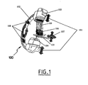
- a radiography apparatus 100 comprises a hoop 102 and a support 105, here a table, able to receive an object 106, here the head of a patient intended to be radiographed by the radiography apparatus 100 for intervention at the level of an anatomical region of interest, for example.
- the arch 102 in substantially semicircular shape, comprises at one of its ends an X-ray source 104 and at its other end an X-ray sensor 103 capable of acquiring X-ray images and radioscopic images of the region of interest previously positioned in the X-ray cone 109 emitted by the source 104.
- the useful surface of the sensor 103 is opposite the X-ray source 104.
- the X-ray source 104 and the X-ray sensor 103 are able to move toward or away from each other (shown by the arrows 101).
- the relative positions of the X-ray source 104 and the X-ray sensor 103 are materialized by the distance separating them and represented by the focal length parameter (DF) that the apparatus Angiography 100 continuously records in storage means provided for this purpose (not shown).
- DF focal length parameter
- the relative positions of the X-ray source 104 and the region of interest of the object 106 to be radiographed are materialized by the distance which separates them and represented by the object distance parameter (OD) that the apparatus of Angiography 100 permanently records in storage means provided for this purpose (not shown).
- OD object distance parameter
- the field of view is defined by a parameter (FOV) permanently recorded by the angiography apparatus 100 in storage means provided for this purpose (not shown).
- FOV field of view
- the arch 102 is able to move according to the three rotations of the space shown diagrammatically by the arrows 108.
- This spatial position of the arch is represented by the angular coordinates ( ⁇ , ⁇ , ⁇ ) that continuously records the X-ray apparatus 100 in storage means provided for this purpose (not shown).
- the support table 105 is able to move according to the three translations of the space shown schematically by the set of arrows 107. As before, the position of the support table 105 is represented by rectangular coordinates (x, y, z) that the X-ray apparatus 100 records in permanence in storage means provided for this purpose (not shown).
- the position of the origin O of the reference frame of the radiography apparatus 100 is the isocenter represented by the point of intersection of the virtual lines passing through the axis of the X-ray tube forming the X-ray source 104, and the center of the image intensifier comprising the X-ray sensor 103 for two different positions of the hoop 102.
- the spatial coordinates of the hoop 102 are determined by angular coordinates ( ⁇ , ⁇ , ⁇ ).
- the position of the origin of the reference frame of the hoop 102 of the radiography apparatus 100 is the isocenter O.
- the spatial coordinates of the table 105 are determined by rectangular coordinates (x, y, z).
- the field of view (FOV) parameter of the X-ray apparatus 100 depends on the characteristics of the equipment of the X-ray apparatus 100 used, and preferably takes one of the values 33, 22, 17, and 13 cm.
- the reference value of the field of view is that taken into account for the realization of the image acquisition series by rotational angiography.
- the focal length parameter (DF) and the object distance parameter (OD) are length characteristics on the axis of the X-ray tube forming the X-ray source 104 passing through the center of the X-ray image intensifier. 103.
- the reference values of the focal lengths (DF) and object (DO) are those taken into account for the realization of the series of images acquisition by rotational angiography.
- the “entries” column of the table indicates all the data provided by the X-ray apparatus 100 that are accessible to the method according to the disclosure.
- the method according to the disclosure is schematized in the "treatment” column of the table of the figure 2 .
- the "outputs" column of the said table of the figure 2 represents the information that the process provides back to the user.
- the number of images obtained per degree of angle is determined by the rotation speed of the hoop 102 and the image acquisition frequency (FREQ).
- the total number of images obtained is determined by the number of images per degree of angles and the extent of the rotation of the hoop 102 (ANG-MAX).
- the native angular images II 1-i of projection different incidences of the region of interest of the object 106 resulting from the series of acquisition by rotational angiography are viewed perpendicularly to the plane of rotation of the hoop 102, under several incidences depending on the position of the hoop 102 during the rotation for acquiring the images from different angles of view.
- the set of angular native images II 1-i are transformed into axial native images IX 1-i .
- the native angular images II 1-i of projection of different incidences of the object 106 containing the region of interest, obtained by rotation of the arch 102 are recalculated and reconstructed in axial projection IX 1-i in order to obtain a stack of images along a predetermined axis in order to be reconstructed in three dimensions taking into account all the images IX 1-i or a part of these images after selection of an image stack I 1-k ( k being between 1 to j) corresponding to the region of interest to be the subject of an intervention.
- These steps are performed directly by the X-ray apparatus 100.
- All of these axial native images I 1-k rotational angiography is recovered by the method according to the invention (arrow 1; figure 2 ) in storage means of the radiography apparatus 100 where they are stored. Then, these native axial images serve as input data I1 1-k (arrow 2) to a reconstruction function F1.
- This function F1 allows reconstruction in three dimensions so as to obtain a volume of the region of interest of the object 106 from these input data axial images I1 1-k .
- the volume V1 thus obtained and corresponding to the output data of function F1 (arrow 3) is composed of a set of several voxels.
- the voxel is the unit of volume corresponding to the smallest element of a three-dimensional space to which individual characteristics such as color or intensity can be attributed.
- the term voxel is the acronym for volume cell element (or volume cell element ).
- the three-dimensional space is thus cut into elementary cubes and each object is described by the cubes that compose it.
- the volume V1 is a three-dimensional matrix of 1 voxels per h voxels per p voxels. Obtaining this three-dimensional matrix representing volume V1 is the culmination of step a) of the method according to the invention.
- steps b), c) and d) of the process according to the invention are preferably carried out intraoperatively, while the operator is working on the patient.
- the second step of the method according to the invention corresponds to step b) and consists of the phases b F2 ) and b F3 ) respectively corresponding to the functions F2 and F3 of the method that we will now describe.
- the input data used by the function F2 are on the one hand the three-dimensional matrix of the volume V1 (arrow 4) and on the other hand the rectangular coordinates (x, y, z) ( arrow 7), at the instant t, of the support table 105, read (arrow 5) in the storage means of these rectangular coordinates of the X-ray apparatus 100, illustrating the position of the table 105 at the instant t, as well as the angular coordinates ( ⁇ , ⁇ , ⁇ ) (arrow 7), at the moment t, of the arch 102, read (arrow 6) in the storage means of these angular coordinates of the radiography apparatus 100, illustrating the position of the arch 102 at time t.
- a last input data item is optionally supplied to the function F2 (arrow 8) and corresponds to the dimensions (n x ' n y' , n z ' ) of a volume V2 calculated and reconstructed by the function F2 from the volume V1 .
- These parameters n x ' , n y' , n z ' are variable and determined at the instant t by the user himself.
- these parameters n x ' , n y' , n z ' are expressed in voxel and can be between 1 voxel and a maximum number of voxels allowing calculation and reconstruction of the volume V2 from the whole volume V1.
- the calculated minimum volume V2min corresponds to the minimum values of (n x ' , n y' , n z ' ) (i.e. 1 voxel) and the calculated maximum volume V2max corresponds to the maximum possible values of (n x ' , n y' , n z ' ) making it possible to reconstruct the volume V2 from the volume V1 in its entirety.
- the function F2 calculates and reconstructs, from the volume V1 at time t, the volume V2 as well as, if appropriate, a projection image IP2 of the volume V2 corresponding to the coordinates (x, y, z) of the table 105 and ( ⁇ , ⁇ , ⁇ ) of the hoop 102, and the dimensions (n x ' , n y' , n z ' ) of the volume V2.
- the volume data V2 and the possible projection image IP2 of the volume V2 are available (the volume V2 being between a volume V2min and a volume V2max corresponding to the extreme values of n x ' , n y' , n z ' ) (arrow 9) .
- the volume V2 thus obtained is therefore a volume reconstructed from the volume VI and parameterized at time t by the coordinates (x, y, z) of the support table 105 and ( ⁇ , ⁇ , ⁇ ) of the hoop 102, as well as the dimensions (n x ' , n y' , n z ' ) ranging from 1 voxel determining a volume V2min of a reconstructed voxel from volume V1 to the maximum dimensions determining a reconstructed volume V2max from the whole volume V1.
- the projection image IP2 is calculated by projection along the axis of incidence, on a plane perpendicular to this axis, of the volume V2 thus determined.
- the position of the region of interest of the object 106 to be X-rayed with respect to the X-ray source 104 and the X-ray sensor 103 at time t determines the geometric magnification parameter (DF / OD), at the moment t, defined by the ratio between the focal length (DF) at time t, and the object distance (DO) at time t.
- DF / OD geometric magnification parameter
- the function F3 calculates, at time t, the geometric magnification and the scaling of the volume V2 reconstructed from the volume V1, as well as the projection image IP2 volume V2.
- the function F3 applies the geometric function of magnification, in this case the geometric function of Thales taking into account that the ratio between a dimension in the volume V2 reconstructed from the volume V1 of the region of interest of the radiographed object 106 or a dimension on the projection image IP2 of the volume V2, and the dimension at the corresponding location in the region of interest, is equal to the ratio between the focal length (DF) and the object distance (OD) of the X-ray source 104 at the corresponding location in the region of interest of the object 106 where the dimension is taken into account.
- FOV field of view
- DO object
- DF focal length
- volume V3 is ultimately a calculated volume and reconstructed from the volume V1 and parameterized at time t by the coordinates (x, y, z) of the table 105, and ( ⁇ , ⁇ , ⁇ ) of the hoop 102, the parameters of geometric enlargement and of scaling of the field of view (FOV), the object distance (OD) and the focal length (DF), as well as the dimensions (n x ' , n y' , n z ' ) ranging from 1 voxel determining a volume V3min of a reconstructed voxel from the volume V1, to the maximum dimensions determining a reconstructed volume V3max from the entire volume V1.
- the calculated volume V3 is in the form of a three-dimensional
- the method according to the invention can transfer the volume V3 and / or the projection image IP3 for display (arrow 15) on suitable display means. to be consulted at the instant t by the user.
- This allows the user to see at time t, on display means, a volume VR of the region of interest (volume V3 transmitted) and / or the projection image IP (transmitted image IP3) of the volume of the region of interest, corresponding to the relative position of the support 105, the hoop 102, and the values of the field of view (FOV), object distance (OD), focal length (DF) and dimensions (n x ' , n y' , n z ' ) at this instant t.
- FOV field of view
- OD object distance
- DF focal length
- dimensions n x ' , n y' , n z '
- the user operator of the method according to the invention can introduce into the region of interest one or more instruments 110 ( Figure 4a ) which he wishes, at the instant t, to know the exact position.
- the operator uses the radiography apparatus to capture a scopie image (IS) (arrow 16) at time t, while the arch 102 is at the angular coordinates ( ⁇ , ⁇ , ⁇ ), the support table 105 at the rectangular coordinates (x, y, z), and the sensor 103 and the X-ray source 104 positioned to have the field of view (FOV), the object distance (OD) and the focal length (DF).
- the image of scopie IS1 thus captured is read (arrow 17), at this moment t, in means for storing the data of the optical image of the radiography apparatus 100, accessible to the method according to the invention.
- the data corresponding to this scopie image IS1 serve as input data (arrow 18) during step c) of the method according to the invention to a function F4.
- This function F4 thus comprises, as input data, the volume V3 and / or the projection image IP3 of volume V3 previously calculated (arrow 19) and the image of scopie IS1, captured and read at time t in the means for storing the data of the optical image of the radiography apparatus 100.
- the function F4 performs the superposition or the subtraction, at time t, in the volume V3 in a determined plane section and / or on the IP3 projection image of the previously calculated volume V3, of the image of scopie IS1 corresponding settings (arrow 16) relative to the coordinates (x, y, z) of the table 105 and ( ⁇ , ⁇ , ⁇ ) of the hoop 102 as well as field of view (FOV), object distance (OD) and focal length (DF) values.
- FOV field of view
- OD object distance
- DF focal length
- the function F4 superimposes or subtracts in the volume V3 in a given plane section and / or on the projection image IP3 of the volume V3, the image of scopie IS1, and / or calculates a projection image IP4 of a volume V4 resulting from the superposition or the subtraction in the volume V3 in a given plane section of the image of scopie IS1, the projection taking place in a plane parallel to the plane of the image of scopie IS1 and in a direction perpendicular to said scopie image IS1.
- the function F4 outputs (arrow 20) the volume V4 and / or the projection image IP4 resulting from the superposition or subtraction previously described.
- the method according to the invention can transfer the volume V4 (ie a VRS volume) and / or the projection image IP4 (ie an IR image) so as to display them (arrow 21) on display means capable of being consulted, at the instant t, by the user.
- This allows the user to see at time t, on display means, the VRS volume of the region of interest and / or the IR projection image of the volume of the region of interest corresponding to the relative position of the support 105, the hoop 102, and the values of the field of view (FOV), object distance (OD), focal length (DF), and dimensions (n x ' , n y' , n z) ' ) at this moment t.
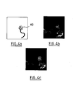
- the user knows the exact position according to the predetermined parameters at this instant t, instruments 110 within the region of interest considered, as illustrated in FIG. Figures 4a to 4c .
- figure 4a is illustrated an image of scopie IS1 taken at a time t, visualizing the instruments and materials 110.
- figure 4b present an IP3 projection image of an arterial structure comprising an intracranial aneurysm, calculated as previously described, corresponding to the parameters (x, y, z), ( ⁇ , ⁇ , ⁇ ), (FOV), (DO), (DF) ) and (n x ' , n y' , n z ' ) associated with the image scopie IS1 of the figure 4a .
- FIG 4c is illustrated an IRS projection image resulting from the superposition carried out by the function F4 during step c) of the method according to the invention where the image of scopie IS1 of the figure 4a was superimposed on the IP3 projection image of the figure 4b illustrating how the operator checks and controls the positioning of his instrumentation 110 during an intervention on an aneurysm as illustrated.
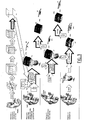
- the Figures 5 and 6 represent the result of calculating an IP projection image according to different positions of the hoop 102.
- the first line of images of the figure 5 corresponds to a variation of the angle ⁇ of the hoop 102 respectively at -90 °, -45 °, 0 °, 45 ° and 90 ° while the other angles ⁇ , ⁇ remain unchanged at 0 °.
- the second line of images illustrates a similar variation of the angle ⁇ whereas ⁇ , ⁇ are fixed at 0 °.
- ⁇ , ⁇ are fixed at 0 ° and ⁇ varies.
- the figure 6 illustrates for fixed spatial coordinates ( ⁇ , ⁇ , ⁇ ) and (x, y, z) the calculation of an IP projection image according to different values for n z ' (n x' and n y ' being unchanged), respectively Voxels, voxels, 45 voxels, 60 voxels and 75 voxels.
- the programming language used is the Java language. It is designed by the association of several software modules or plug-ins (or even plugins according to the Anglo-Saxon term) adding each of the features as we have described them previously.
- they allow basic functions for processing images of any format including the DICOM format used in radiology. These functions are reading, displaying, editing, analyzing, processing, saving and printing such images. They make it possible to calculate statistics on a pixel, or a voxel, or on a defined area by selection. Distance and angle measurements can be made. They can also perform processing on densities and support most of the standard imaging functions such as contrast modification, edge detection or median filters. They can further perform geometric transformations such as magnification, scaling, rotation; all the functions of analysis and previous treatments being usable at any magnification.
- each function specific to the method according to the invention is performed by a dedicated plug-in.
- a plug-in allows the calculation and reconstruction of orthogonal slices with respect to a given axis of a volume or a region of interest.
- Another plug-in deals with the computation and reconstruction of a volume, and its associated projection image, by performing a volume rendering and by rendering said rendering on any set of voxels and / or on any stack of cuts.
- This plug-in allows volume reconstruction along a specific axis.
- the volume can be rotated, enlarged, or reduced.
- the interpolation of the volume rendering is a trilinear interpolation, known per se, except for the end sections of the stack and / or the end voxels of the voxel set where this trilinear interpolation is impossible. .
- nearest-neighbor interpolation known per se, is used instead of trilinear interpolation.
- Another plug-in makes it possible to project along an axis, as an example in maximum projection intensity (M.I.P). This makes it possible to calculate the projection image IP3 of the volume V3, for example.
- M.I.P maximum projection intensity
- the method according to the invention described above uses the various plug-ins previously cited to calculate the projection image of a volume.
- Three-dimensional imaging acquired by rotational angiography allows a better understanding of the real anatomy of a lesion, an organ, or a part of an organ by allowing the visualization of this structure from every angle of view. required. His interest is essentially diagnostic. Therapeutically, its interest is limited to the optimization of the relevant angles of view, either before treatment to define a priori a therapeutic strategy or after treatment to evaluate the therapeutic result.
- the use of three-dimensional reference imaging in per-therapeutics is a new concept, never elaborated until now in projection imaging, for, at any moment during the intervention, to adapt and adjust its therapeutic decisions and strategies, to assist and control its technical gesture and to evaluate the therapeutic results.
- a framework for applying the method according to the invention is described according to a projection imaging technique from an angiography apparatus, for the investigation and the endovascular treatment of an intracranial aneurysm.
- the region of interest is represented by the afferent intracranial arterial vascular network carrying an intracranial aneurysm.
- Images that reconstruct the volume of the three-dimensional region of interest can be come from images or volumes previously reworked, without being exhaustive, the reconstructions of images or volumes from all the techniques mentioned above.
- the imaging technique producing the real-time active images and the one allowing the acquisition for the reconstruction of the volume of the region of interest in three dimensions can be without being exhaustive either the same technique or different techniques and thus requiring the identification of the volume of the region of interest according to a repository either internal or external to the subject on which depends the region of interest.
Landscapes
- Health & Medical Sciences (AREA)
- Life Sciences & Earth Sciences (AREA)
- Medical Informatics (AREA)
- Engineering & Computer Science (AREA)
- Radiology & Medical Imaging (AREA)
- Molecular Biology (AREA)
- Biophysics (AREA)
- Nuclear Medicine, Radiotherapy & Molecular Imaging (AREA)
- Optics & Photonics (AREA)
- Pathology (AREA)
- Physics & Mathematics (AREA)
- Biomedical Technology (AREA)
- Heart & Thoracic Surgery (AREA)
- High Energy & Nuclear Physics (AREA)
- Surgery (AREA)
- Animal Behavior & Ethology (AREA)
- General Health & Medical Sciences (AREA)
- Public Health (AREA)
- Veterinary Medicine (AREA)
- Vascular Medicine (AREA)
- Dentistry (AREA)
- Oral & Maxillofacial Surgery (AREA)
- Apparatus For Radiation Diagnosis (AREA)
Claims (12)
- Navigationsverfahren innerhalb einer Region von Bedeutung, das dazu bestimmt ist, in einem Radiographie-System (100) angewandt zu werden, das in der Art gestaltet ist, dass es eine Röntgenstrahlenquelle (104) und Speichervorrichtungen (103) umfasst, die gegenüber der besagten Quelle angeordnet sind, sowie einen Support (105), auf dem ein zu röntgender Gegenstand (106) umfassend die Region von Bedeutung angeordnet werden soll, wobei das Verfahren die folgenden Schritte umfasst:a) die Erfassung dreidimensionaler Bilddaten eines Volumens (V1) der Region von Bedeutung;b) die Berechnung, zu einem Zeitpunkt t, eines zweidimensionalen Projektionsbildes (IP, IP2, IP3) des gesamten Volumens (V1) oder eines Teils davon und/ oder eines Unter-Volumens (V2, V3, VR) des besagten Volumens (V1) in Anhängigkeit von den Parametern umfassend die Positionen des Supports (105), der Quelle (104) und der Speichervorrichtungen (103), das Sichtfeld (FOV), die Fokal- (DF) und Gegenstandsabstände (DO);c) die Überlagerung oder die Subtraktion des Projektionsbildes (IP, IP3) und/ oder des unter-Volumens (V3, VR) in einem bestimmten ebenen Schnitt von einem Röntgenaufnahmebild (IS1), das den besagten Parametern zum Zeitpunkt t zugeordnet wird;d) die Anzeige eines Bildes (TR) und/ oder eines Volumens (VRS) resultierend aus dem Schritt c), und/ oder des Projektionsbildes (IP, IP2, IP3) und/ oder des Unter-Volumens (V2, V3, VR) auf Anzeigevorrichtungen, dadurch gekennzeichnet, dass das Verfahren diee) Wiederholung der Schritte b), c) und d) bei jeder Wertänderung in den besagten Parametern umfasst.
- Verfahren nach Anspruch 1, dadurch gekennzeichnet, dass der Schritt b) die folgenden Unterschritte umfasst:- b1) das Ablesen in den Speichervorrichtungen des Radiographie-Systems einer Postition (x, y, z) des Supports, einer Position (α, β, γ) der Quelle und der Speichervorrichtungen, des Sichtfeldes (FOV), der Fokal- (DF) und Gegenstandsabstände (DO); und,- b2) die Berechnung des Projektionsbildes (IP, IP3) und/ oder des Unter-Volumens (V3, VR) in Abhängigkeit von den abgelesene Parametern.
- Verfahren nach Anspruch 1 oder 2, dadurch gekennzeichnet, dass der Schritt b) die folgenden Unterschritte umfasst:- b1) das Ablesen in den Speichervorrichtungen des Radiographie-Systems einer Position (x, y, z) des Supports, einer Position (α, β, γ) der Quelle und der Speichervorrichtungen;- b2) die Berechnung eines Unter-Volumens V2 des Volumens V1 in Abhängigkeit von diesen Positionen;- b3) das Ablesen in den Speichervorrichtungen des Radiographie-Systems des Sichtfeldes (FOV), der Fokal- (DF) und Gegenstandsabstände (DO);- b4) die Berechnung eines korrigierten Volumens V3 des Unter-Volumens V2 in Abhängigkeit vom Sichtfeld (FOV), der Fokal- (DF) und Gegenstandsabstände (DO);- b5) die eventuelle Berechnung des Projektionsbildes (IP, IP3) ausgehend vom korrigierten Volumen.
- Verfahren nach Anspruch 3, dadurch gekennzeichnet, dass das korrigierte Volumen V3 gemäß einer geometrischen Vergrößerung und einer Normierung in Abhängigkeit vom Sichtfeld (FOV) und den Fokal- (DF) und Gegenstandsabständen (DO) berechnet wird.
- Verfahren nach Anspruch 3, dadurch gekennzeichnet, dass beim Schritt b2) darüber hinaus ein Projektionsbild (IP2) des Unter-Volumens V2 in Abhängigkeit von den besagten Positionen berechnet wird.
- Verfahren nach Anspruch 5, dadurch gekennzeichnet, dass das Projektionsbild (IP, IP3) beim Schritt b5) ein korrigiertes Bild des Projektionsbildes (IP2) in Abhängigkeit vom Sichtfeld (FOV) und den Fokal- (DF) und Gegenstandsabständen (DO) ist.
- Verfahren nach Anspruch 4 oder 6, dadurch gekennzeichnet, dass die Berechnung der Korrektur durch die Abwendung einer geometrischen Vergrößerungsfunktion erfolgt.
- Verfahren nach einem der Ansprüche 3 bis 7, dadurch gekennzeichnet, dass die Berechnung des Unter-Volumens V2 die folgenden Schritte umfasst:i) die Bestimmung im Volumen V1 einer Lichteinfallachse in Abhängigkeit von der Position (α, β, γ) der Quelle (104) und der Speichervorrichtungen (103) in Bezug auf ein Bezugssystem des Radiographie-Systems, wobei einer der Ausgangspunkte ein Isozentrum des besagten Radiographie-Systems ist;ii) die Bestimmung im Volumen V1 eines Zentrums des Unter-Volumens V2 in Abhängigkeit von der Position (x, y, z) des Supports (105); und,iii) die Berechnung und Rekonstruktion des Unter-Volumens V2 ausgehend vom Volumen V1 in einer Rekonstruktionsachse, die parallel zur Lichteinfallachse verläuft.
- Verfahren nach einen der Ansprüche 3 bis 8, dadurch gekennzeichnet, dass das Unter-Volumen V2 Abmessungen nx' mal ny' mal nz' aufweist, die von einem Bediener festgelegt werden.
- Verfahren nach einem der vorherigen Ansprüche, dadurch gekennzeichnet, dass der Schritt a) die folgenden Unter-Schritte umfasst:- a1) die Erfassung einer Reihe von Schnitten der Region von Bedeutung; und,- a2) die Rekonstruktion des Volumens V1 in Form einer dreidimensionalen Voxel-Matrix.
- Verfahren nach einem der Ansprüche 1 bis 10, dadurch gekennzeichnet, dass der Schritt c) die folgenden Unter-Schritte umfasst:c1) das Lesen des Röntgenaüfnahmebildes IS1 in den Speichervorrichtungen des Radiographic-Systems,c2) die Überlagerung oder die Subtraktion vom Projektionsbild (IP, IP3) und/ oder des unter-Volumens in einem bestimmten ebenen Schnitt des Röntqenaufnahmebildes IS1.
- Radiographie-System, das in der Art gestaltet ist, dass es eine Röntgenstrahlenquelle und Speichervorrichtungen umfasst, die gegenüber der besagten Quelle angeordnet sind, sowie einen Support, auf dem ein zu röntgender Gegenstand umfassend die Region von Bedeutung angeordnet werden soll, Vorrichtungen zum Erfassen von dreidimensionalen Daten, die mit den Speichervorrichtungen verbunden sind, Berechnungsverrichtungen und Anzeigevorrichtungen, dadurch gekennzeichnet, dass alle diese Vorrichtungen so angeordnet sind, dass sie das Verfahren nach einem der vorherigen Ansprüche anwenden.
Applications Claiming Priority (3)
| Application Number | Priority Date | Filing Date | Title |
|---|---|---|---|
| FR0204296 | 2002-04-05 | ||
| FR0204296A FR2838043B1 (fr) | 2002-04-05 | 2002-04-05 | Systeme d'aide a la navigation en temps reel pour dispositif de radiographie |
| PCT/FR2003/001075 WO2003084380A2 (fr) | 2002-04-05 | 2003-04-04 | System d'aide a la navigation en temps reel pour dispositif de radiographie |
Publications (2)
| Publication Number | Publication Date |
|---|---|
| EP1496800A2 EP1496800A2 (de) | 2005-01-19 |
| EP1496800B1 true EP1496800B1 (de) | 2013-01-23 |
Family
ID=28052160
Family Applications (1)
| Application Number | Title | Priority Date | Filing Date |
|---|---|---|---|
| EP03745824A Expired - Lifetime EP1496800B1 (de) | 2002-04-05 | 2003-04-04 | Echtzeit-navigationshilfesystem und radiographie-system |
Country Status (8)
| Country | Link |
|---|---|
| US (1) | US20080037702A1 (de) |
| EP (1) | EP1496800B1 (de) |
| CN (1) | CN1722981B (de) |
| AU (1) | AU2003246780A1 (de) |
| BR (1) | BR0309168A (de) |
| CA (1) | CA2481446A1 (de) |
| FR (1) | FR2838043B1 (de) |
| WO (1) | WO2003084380A2 (de) |
Families Citing this family (12)
| Publication number | Priority date | Publication date | Assignee | Title |
|---|---|---|---|---|
| US20100215150A1 (en) * | 2002-04-05 | 2010-08-26 | Vallee Jean-Noel | Real-time Assisted Guidance System for a Radiography Device |
| US7103136B2 (en) * | 2003-12-22 | 2006-09-05 | General Electric Company | Fluoroscopic tomosynthesis system and method |
| CN1839754B (zh) * | 2004-03-30 | 2010-12-01 | 美国西门子医疗解决公司 | 降低x射线成像过程中患者辐射曝光的方法和数据处理系统 |
| FR2879433B1 (fr) * | 2004-12-17 | 2008-01-04 | Gen Electric | Procede pour determiner une geometrie d'acquisition d'un systeme medical |
| US7853061B2 (en) | 2007-04-26 | 2010-12-14 | General Electric Company | System and method to improve visibility of an object in an imaged subject |
| US20090074265A1 (en) * | 2007-09-17 | 2009-03-19 | Capsovision Inc. | Imaging review and navigation workstation system |
| CN102068764A (zh) * | 2010-10-29 | 2011-05-25 | 夏廷毅 | 一种图像引导伽马刀治疗验证系统 |
| KR20140092437A (ko) * | 2012-12-27 | 2014-07-24 | 삼성전자주식회사 | 엑스선 영상 장치 및 엑스선 영상 장치의 제어 방법 |
| DE102014200915A1 (de) * | 2014-01-20 | 2015-07-23 | Siemens Aktiengesellschaft | Verfahren zum Bereitstellen eines räumlichen anatomischen Modells eines Körperteils eines Patienten |
| US11373330B2 (en) | 2018-03-27 | 2022-06-28 | Siemens Healthcare Gmbh | Image-based guidance for device path planning based on penalty function values and distances between ROI centerline and backprojected instrument centerline |
| JP7568426B2 (ja) * | 2020-05-25 | 2024-10-16 | キヤノンメディカルシステムズ株式会社 | 医用情報処理装置、x線診断装置及びプログラム |
| CN114903507B (zh) * | 2022-05-16 | 2023-06-09 | 张海光 | 一种医学图像数据处理系统及方法 |
Family Cites Families (6)
| Publication number | Priority date | Publication date | Assignee | Title |
|---|---|---|---|---|
| JP4054402B2 (ja) * | 1997-04-25 | 2008-02-27 | 株式会社東芝 | X線断層撮影装置 |
| US5274551A (en) * | 1991-11-29 | 1993-12-28 | General Electric Company | Method and apparatus for real-time navigation assist in interventional radiological procedures |
| DE19620371A1 (de) * | 1996-05-21 | 1997-12-04 | Philips Patentverwaltung | Röntgenaufnahme-Verfahren |
| US5960054A (en) * | 1997-11-26 | 1999-09-28 | Picker International, Inc. | Angiographic system incorporating a computerized tomographic (CT) scanner |
| US6075837A (en) * | 1998-03-19 | 2000-06-13 | Picker International, Inc. | Image minifying radiographic and fluoroscopic x-ray system |
| US6711433B1 (en) * | 1999-09-30 | 2004-03-23 | Siemens Corporate Research, Inc. | Method for providing a virtual contrast agent for augmented angioscopy |
-
2002
- 2002-04-05 FR FR0204296A patent/FR2838043B1/fr not_active Expired - Fee Related
-
2003
- 2003-04-04 CN CN03813081.5A patent/CN1722981B/zh not_active Expired - Fee Related
- 2003-04-04 EP EP03745824A patent/EP1496800B1/de not_active Expired - Lifetime
- 2003-04-04 CA CA002481446A patent/CA2481446A1/fr not_active Abandoned
- 2003-04-04 WO PCT/FR2003/001075 patent/WO2003084380A2/fr not_active Ceased
- 2003-04-04 AU AU2003246780A patent/AU2003246780A1/en not_active Abandoned
- 2003-04-04 BR BR0309168-6A patent/BR0309168A/pt not_active IP Right Cessation
- 2003-04-04 US US10/510,306 patent/US20080037702A1/en not_active Abandoned
Also Published As
| Publication number | Publication date |
|---|---|
| WO2003084380A3 (fr) | 2004-04-01 |
| CN1722981A (zh) | 2006-01-18 |
| CA2481446A1 (fr) | 2003-10-16 |
| CN1722981B (zh) | 2011-05-18 |
| EP1496800A2 (de) | 2005-01-19 |
| FR2838043B1 (fr) | 2005-03-11 |
| BR0309168A (pt) | 2005-02-22 |
| WO2003084380A2 (fr) | 2003-10-16 |
| US20080037702A1 (en) | 2008-02-14 |
| AU2003246780A8 (en) | 2003-10-20 |
| FR2838043A1 (fr) | 2003-10-10 |
| AU2003246780A1 (en) | 2003-10-20 |
Similar Documents
| Publication | Publication Date | Title |
|---|---|---|
| RU2471239C2 (ru) | Визуализация трехмерных изображений в комбинации с двумерными проекционными изображениями | |
| EP2328477B1 (de) | Interventionelle bildgebung und datenaufbereitung | |
| JP6030340B2 (ja) | 最適投影画像をコンピュータの実行により決定するための方法と装置 | |
| KR20190051384A (ko) | X선 단층 영상 데이터를 생성하는 방법 및 장치 | |
| FR2864301A1 (fr) | Systeme et procede de tomosynthese radioscopique | |
| EP1496800B1 (de) | Echtzeit-navigationshilfesystem und radiographie-system | |
| JP6370280B2 (ja) | 断層画像生成装置、方法およびプログラム | |
| FR3110744A1 (fr) | Procédé et système de recalage d’images contenant des structures anatomiques | |
| CN101082991A (zh) | 利用投影重建对象的方法以及执行该方法的装置 | |
| FR2842931A1 (fr) | Amelioration d'un procede pour afficher des variations temporelles dans des images superposees dans l'espace. | |
| FR2812741A1 (fr) | Procede et dispositif de reconstruction d'une image tridimensionnelle dynamique d'un objet parcouru par un produit de contraste | |
| EP2024935A1 (de) | Verfahren und vorrichtung zur rekonstruktion eines bildes | |
| JP3987024B2 (ja) | 横方向のフィルタリング処理を用いたトモシンセシス画像を強調する方法及びシステム | |
| US11786193B2 (en) | Metal artifacts reduction in cone beam reconstruction | |
| CN1538796A (zh) | 采用原立体数据组进行数字减影血管造影的方法 | |
| US12190436B2 (en) | Systems and methods for generating multi-view synthetic dental radiographs for intraoral tomosynthesis | |
| US20240122564A1 (en) | Systems and methods for low-dose ai-based imaging | |
| JP2005103263A (ja) | 断層撮影能力のある画像形成検査装置の作動方法およびx線コンピュータ断層撮影装置 | |
| US20100215150A1 (en) | Real-time Assisted Guidance System for a Radiography Device | |
| JP2023167122A (ja) | X線ct装置、および、高画質画像生成装置 | |
| WO2021163662A1 (en) | Ultra-fast-pitch acquisition and reconstruction in helical computed tomography | |
| FR2887058A1 (fr) | Procede et dispositif de reconstruction 3d d'un objet a partir de plusieurs images 2d |
Legal Events
| Date | Code | Title | Description |
|---|---|---|---|
| PUAI | Public reference made under article 153(3) epc to a published international application that has entered the european phase |
Free format text: ORIGINAL CODE: 0009012 |
|
| 17P | Request for examination filed |
Effective date: 20041105 |
|
| AK | Designated contracting states |
Kind code of ref document: A2 Designated state(s): AT BE BG CH CY CZ DE DK EE ES FI FR GB GR HU IE IT LI LU MC NL PT RO SE SI SK TR |
|
| AX | Request for extension of the european patent |
Extension state: AL LT LV MK |
|
| 17Q | First examination report despatched |
Effective date: 20101227 |
|
| APBK | Appeal reference recorded |
Free format text: ORIGINAL CODE: EPIDOSNREFNE |
|
| APBN | Date of receipt of notice of appeal recorded |
Free format text: ORIGINAL CODE: EPIDOSNNOA2E |
|
| APBR | Date of receipt of statement of grounds of appeal recorded |
Free format text: ORIGINAL CODE: EPIDOSNNOA3E |
|
| APBV | Interlocutory revision of appeal recorded |
Free format text: ORIGINAL CODE: EPIDOSNIRAPE |
|
| GRAP | Despatch of communication of intention to grant a patent |
Free format text: ORIGINAL CODE: EPIDOSNIGR1 |
|
| GRAS | Grant fee paid |
Free format text: ORIGINAL CODE: EPIDOSNIGR3 |
|
| GRAA | (expected) grant |
Free format text: ORIGINAL CODE: 0009210 |
|
| AK | Designated contracting states |
Kind code of ref document: B1 Designated state(s): AT BE BG CH CY CZ DE DK EE ES FI FR GB GR HU IE IT LI LU MC NL PT RO SE SI SK TR |
|
| REG | Reference to a national code |
Ref country code: GB Ref legal event code: FG4D Free format text: NOT ENGLISH |
|
| REG | Reference to a national code |
Ref country code: CH Ref legal event code: EP |
|
| REG | Reference to a national code |
Ref country code: CH Ref legal event code: EP Ref country code: AT Ref legal event code: REF Ref document number: 594517 Country of ref document: AT Kind code of ref document: T Effective date: 20130215 |
|
| REG | Reference to a national code |
Ref country code: IE Ref legal event code: FG4D Free format text: LANGUAGE OF EP DOCUMENT: FRENCH |
|
| REG | Reference to a national code |
Ref country code: DE Ref legal event code: R096 Ref document number: 60343185 Country of ref document: DE Effective date: 20130321 |
|
| REG | Reference to a national code |
Ref country code: NL Ref legal event code: T3 |
|
| REG | Reference to a national code |
Ref country code: AT Ref legal event code: MK05 Ref document number: 594517 Country of ref document: AT Kind code of ref document: T Effective date: 20130123 |
|
| PG25 | Lapsed in a contracting state [announced via postgrant information from national office to epo] |
Ref country code: CY Free format text: LAPSE BECAUSE OF FAILURE TO SUBMIT A TRANSLATION OF THE DESCRIPTION OR TO PAY THE FEE WITHIN THE PRESCRIBED TIME-LIMIT Effective date: 20130123 Ref country code: AT Free format text: LAPSE BECAUSE OF FAILURE TO SUBMIT A TRANSLATION OF THE DESCRIPTION OR TO PAY THE FEE WITHIN THE PRESCRIBED TIME-LIMIT Effective date: 20130123 Ref country code: ES Free format text: LAPSE BECAUSE OF FAILURE TO SUBMIT A TRANSLATION OF THE DESCRIPTION OR TO PAY THE FEE WITHIN THE PRESCRIBED TIME-LIMIT Effective date: 20130504 Ref country code: BG Free format text: LAPSE BECAUSE OF FAILURE TO SUBMIT A TRANSLATION OF THE DESCRIPTION OR TO PAY THE FEE WITHIN THE PRESCRIBED TIME-LIMIT Effective date: 20130423 Ref country code: SE Free format text: LAPSE BECAUSE OF FAILURE TO SUBMIT A TRANSLATION OF THE DESCRIPTION OR TO PAY THE FEE WITHIN THE PRESCRIBED TIME-LIMIT Effective date: 20130123 |
|
| PG25 | Lapsed in a contracting state [announced via postgrant information from national office to epo] |
Ref country code: GR Free format text: LAPSE BECAUSE OF FAILURE TO SUBMIT A TRANSLATION OF THE DESCRIPTION OR TO PAY THE FEE WITHIN THE PRESCRIBED TIME-LIMIT Effective date: 20130424 Ref country code: PT Free format text: LAPSE BECAUSE OF FAILURE TO SUBMIT A TRANSLATION OF THE DESCRIPTION OR TO PAY THE FEE WITHIN THE PRESCRIBED TIME-LIMIT Effective date: 20130523 Ref country code: SI Free format text: LAPSE BECAUSE OF FAILURE TO SUBMIT A TRANSLATION OF THE DESCRIPTION OR TO PAY THE FEE WITHIN THE PRESCRIBED TIME-LIMIT Effective date: 20130123 Ref country code: FI Free format text: LAPSE BECAUSE OF FAILURE TO SUBMIT A TRANSLATION OF THE DESCRIPTION OR TO PAY THE FEE WITHIN THE PRESCRIBED TIME-LIMIT Effective date: 20130123 |
|
| BERE | Be: lapsed |
Owner name: NIOCHE, CHRISTOPHE Effective date: 20130430 Owner name: SABBAH, PATRICK Effective date: 20130430 Owner name: VALLEE, JEAN-NOEL Effective date: 20130430 |
|
| PG25 | Lapsed in a contracting state [announced via postgrant information from national office to epo] |
Ref country code: EE Free format text: LAPSE BECAUSE OF FAILURE TO SUBMIT A TRANSLATION OF THE DESCRIPTION OR TO PAY THE FEE WITHIN THE PRESCRIBED TIME-LIMIT Effective date: 20130123 Ref country code: DK Free format text: LAPSE BECAUSE OF FAILURE TO SUBMIT A TRANSLATION OF THE DESCRIPTION OR TO PAY THE FEE WITHIN THE PRESCRIBED TIME-LIMIT Effective date: 20130123 Ref country code: RO Free format text: LAPSE BECAUSE OF FAILURE TO SUBMIT A TRANSLATION OF THE DESCRIPTION OR TO PAY THE FEE WITHIN THE PRESCRIBED TIME-LIMIT Effective date: 20130123 Ref country code: CZ Free format text: LAPSE BECAUSE OF FAILURE TO SUBMIT A TRANSLATION OF THE DESCRIPTION OR TO PAY THE FEE WITHIN THE PRESCRIBED TIME-LIMIT Effective date: 20130123 Ref country code: SK Free format text: LAPSE BECAUSE OF FAILURE TO SUBMIT A TRANSLATION OF THE DESCRIPTION OR TO PAY THE FEE WITHIN THE PRESCRIBED TIME-LIMIT Effective date: 20130123 |
|
| PG25 | Lapsed in a contracting state [announced via postgrant information from national office to epo] |
Ref country code: MC Free format text: LAPSE BECAUSE OF FAILURE TO SUBMIT A TRANSLATION OF THE DESCRIPTION OR TO PAY THE FEE WITHIN THE PRESCRIBED TIME-LIMIT Effective date: 20130123 |
|
| PLBE | No opposition filed within time limit |
Free format text: ORIGINAL CODE: 0009261 |
|
| REG | Reference to a national code |
Ref country code: CH Ref legal event code: PL |
|
| STAA | Information on the status of an ep patent application or granted ep patent |
Free format text: STATUS: NO OPPOSITION FILED WITHIN TIME LIMIT |
|
| PG25 | Lapsed in a contracting state [announced via postgrant information from national office to epo] |
Ref country code: IT Free format text: LAPSE BECAUSE OF FAILURE TO SUBMIT A TRANSLATION OF THE DESCRIPTION OR TO PAY THE FEE WITHIN THE PRESCRIBED TIME-LIMIT Effective date: 20130123 |
|
| 26N | No opposition filed |
Effective date: 20131024 |
|
| REG | Reference to a national code |
Ref country code: IE Ref legal event code: MM4A |
|
| PG25 | Lapsed in a contracting state [announced via postgrant information from national office to epo] |
Ref country code: CH Free format text: LAPSE BECAUSE OF NON-PAYMENT OF DUE FEES Effective date: 20130430 Ref country code: LI Free format text: LAPSE BECAUSE OF NON-PAYMENT OF DUE FEES Effective date: 20130430 Ref country code: BE Free format text: LAPSE BECAUSE OF NON-PAYMENT OF DUE FEES Effective date: 20130430 |
|
| REG | Reference to a national code |
Ref country code: DE Ref legal event code: R097 Ref document number: 60343185 Country of ref document: DE Effective date: 20131024 |
|
| PG25 | Lapsed in a contracting state [announced via postgrant information from national office to epo] |
Ref country code: IE Free format text: LAPSE BECAUSE OF NON-PAYMENT OF DUE FEES Effective date: 20130404 |
|
| PG25 | Lapsed in a contracting state [announced via postgrant information from national office to epo] |
Ref country code: TR Free format text: LAPSE BECAUSE OF FAILURE TO SUBMIT A TRANSLATION OF THE DESCRIPTION OR TO PAY THE FEE WITHIN THE PRESCRIBED TIME-LIMIT Effective date: 20130123 |
|
| PG25 | Lapsed in a contracting state [announced via postgrant information from national office to epo] |
Ref country code: LU Free format text: LAPSE BECAUSE OF NON-PAYMENT OF DUE FEES Effective date: 20130404 Ref country code: HU Free format text: LAPSE BECAUSE OF FAILURE TO SUBMIT A TRANSLATION OF THE DESCRIPTION OR TO PAY THE FEE WITHIN THE PRESCRIBED TIME-LIMIT; INVALID AB INITIO Effective date: 20030404 |
|
| REG | Reference to a national code |
Ref country code: FR Ref legal event code: PLFP Year of fee payment: 14 |
|
| REG | Reference to a national code |
Ref country code: FR Ref legal event code: PLFP Year of fee payment: 15 |
|
| REG | Reference to a national code |
Ref country code: NL Ref legal event code: MM Effective date: 20170501 |
|
| GBPC | Gb: european patent ceased through non-payment of renewal fee |
Effective date: 20170404 |
|
| PG25 | Lapsed in a contracting state [announced via postgrant information from national office to epo] |
Ref country code: NL Free format text: LAPSE BECAUSE OF NON-PAYMENT OF DUE FEES Effective date: 20170501 |
|
| PG25 | Lapsed in a contracting state [announced via postgrant information from national office to epo] |
Ref country code: GB Free format text: LAPSE BECAUSE OF NON-PAYMENT OF DUE FEES Effective date: 20170404 |
|
| REG | Reference to a national code |
Ref country code: FR Ref legal event code: PLFP Year of fee payment: 16 |
|
| REG | Reference to a national code |
Ref country code: NL Ref legal event code: NE Effective date: 20180509 |
|
| REG | Reference to a national code |
Ref country code: NL Ref legal event code: NF Effective date: 20180711 |
|
| PG25 | Lapsed in a contracting state [announced via postgrant information from national office to epo] |
Ref country code: NL Free format text: LAPSE BECAUSE OF NON-PAYMENT OF DUE FEES Effective date: 20170501 |
|
| PGRI | Patent reinstated in contracting state [announced from national office to epo] |
Ref country code: NL Effective date: 20180711 |
|
| REG | Reference to a national code |
Ref country code: GB Ref legal event code: S28 Free format text: APPLICATION FILED |
|
| REG | Reference to a national code |
Ref country code: GB Ref legal event code: S28 Free format text: RESTORATION ALLOWED Effective date: 20190221 |
|
| PGFP | Annual fee paid to national office [announced via postgrant information from national office to epo] |
Ref country code: NL Payment date: 20190429 Year of fee payment: 17 |
|
| PGFP | Annual fee paid to national office [announced via postgrant information from national office to epo] |
Ref country code: DE Payment date: 20190426 Year of fee payment: 17 |
|
| PGFP | Annual fee paid to national office [announced via postgrant information from national office to epo] |
Ref country code: FR Payment date: 20190426 Year of fee payment: 17 |
|
| PGFP | Annual fee paid to national office [announced via postgrant information from national office to epo] |
Ref country code: GB Payment date: 20190425 Year of fee payment: 17 |
|
| REG | Reference to a national code |
Ref country code: DE Ref legal event code: R119 Ref document number: 60343185 Country of ref document: DE |
|
| REG | Reference to a national code |
Ref country code: NL Ref legal event code: MM Effective date: 20200501 |
|
| PG25 | Lapsed in a contracting state [announced via postgrant information from national office to epo] |
Ref country code: DE Free format text: LAPSE BECAUSE OF NON-PAYMENT OF DUE FEES Effective date: 20201103 Ref country code: FR Free format text: LAPSE BECAUSE OF NON-PAYMENT OF DUE FEES Effective date: 20200430 |
|
| GBPC | Gb: european patent ceased through non-payment of renewal fee |
Effective date: 20200404 |
|
| PG25 | Lapsed in a contracting state [announced via postgrant information from national office to epo] |
Ref country code: NL Free format text: LAPSE BECAUSE OF NON-PAYMENT OF DUE FEES Effective date: 20200501 |
|
| PG25 | Lapsed in a contracting state [announced via postgrant information from national office to epo] |
Ref country code: GB Free format text: LAPSE BECAUSE OF NON-PAYMENT OF DUE FEES Effective date: 20200404 |