The present invention relates to a display with a
liquid crystal panel and a color filter arranged on an
electroluminescence panel.
Liquid crystal displays are widely used as a display
in, for example, portable devices such as a portable
computer. Further, liquid crystal displays using an
organic electroluminescence element as a backlight are
known in the art. A liquid crystal display that lights the
backlight in dark places to function as a transmissive type
display and that does not light the backlight in bright
places to function as a reflective type display is proposed
to satisfy the requirements of a compact and light portable
device with low power-consumption. (Refer to Japanese
Laid-Open Patent Publication No. 3-1896.27)
Japanese Laid-Open Patent Publication No. 7-294916
describes a color liquid crystal display for which the
light source is organic electroluminescence elements that
emit monochromatic light. The electroluminescence elements
are arranged in alignment with the liquid crystal display
pixel pattern (Refer to Japanese Laid-Open Patent
Publication No. 7-294916). Color filters are not used in
this display. Thus, the light exiting from the organic
electroluminescence elements is not absorbed or diffused at
the color filters. This allows an image of high brightness
to be displayed.
However, contrast decreases in a bright environment
such as when using the display outdoors during the daytime.
This lowers the quality of the image. Further, since
ambient light cannot be used as the light source, the
amount of power consumption increases. In order to realize
a full color display, an organic electroluminescence layer
constituting the organic electroluminescence element needs
to be formed from three layers, which are a red color
luminescence layer, a green color luminescence layer, and a
blue color luminescent layer. This makes the manufacturing
of the display complicated.
It is an object of the present invention to provide an
easily manufactured display that displays a color image
suitable for the environment.
To achieve the above object, the present invention
provides a display for displaying an image. The display is
provided with a color filter and a transmissive or semi-transmissive
liquid crystal panel, which includes a display
surface, a rear surface located on the opposite side of the
display surface, and a plurality of liquid crystal sub-pixels.
An electroluminescence panel is arranged on the
rear surface side of the liquid crystal panel. The
electroluminescence panel includes a plurality of EL sub-pixels,
each corresponding to one of the liquid crystal
sub-pixels, and a light reflecting portion for reflecting
light entering from the liquid crystal panel back towards
the liquid crystal panel. Each EL sub-pixel emits white
light and has light transmissivity relative to at least
light having a wavelength that enables transmission through
the corresponding color filter. A first driving means
drives the liquid crystal panel. A second driving means
drives the electroluminescence panel. A selecting means
determines whether to use the first driving means and
whether to use the second driving means to display an
image.
A further aspect of the present invention provides a
display for displaying an image. The display is provided
with a color filter and a transmissive or semi-transmissive
liquid crystal panel, which includes a display surface, a
rear surface located on the opposite side of the display
surface, and a plurality of liquid crystal sub-pixels. An
electroluminescence panel is arranged on the rear surface
side of the liquid crystal panel. The electroluminescence
panel includes a plurality of EL sub-pixels, each
corresponding to one of the liquid crystal sub-pixels, and
a light reflecting portion for reflecting light entering
from the liquid crystal panel back towards the liquid
crystal panel. Each EL sub-pixel emits white light and has
light transmissivity relative to at least light having a
wavelength that enables transmission through the
corresponding color filter. A first driving means drives
the liquid crystal panel. A second driving means drives
the electroluminescence panel. A third driving means
simultaneously drives the liquid crystal panel and the
electroluminescence panel. A selecting means determines
which one of the first driving means, the second driving
means, and the third driving means to use to display the
image. When the image is displayed using the third driving
means, the third driving means controls the first and the
second driving means to display an image on the liquid
crystal panel while causing EL sub-pixels corresponding to
liquid crystal sub-pixels that are in a black display state
to be in a non-light emitting state and the other EL sub-pixels
to be in a light emitting state.
Other aspects and advantages of the present invention
will become apparent from the following description, taken
in conjunction with the accompanying drawings, illustrating
by way of example the principles of the invention.
The invention, together with objects and advantages
thereof, may best be understood by reference to the
following description of the presently preferred embodiment
together with the accompanying drawings in which:
A display according to a preferred embodiment of the
present invention.will now be described. The bottom side
as viewed in Fig. 1 corresponds to the display side
(direction of light exit) of the display. In the drawings,
the size of each member differs from the actual size.
As shown in Fig. 1, the display 11 includes a liquid
crystal panel 13 and a color filter 20 arranged on an
organic electroluminescence panel (organic EL panel) 12.
The organic EL panel 12 and the liquid crystal panel 13 are
both formed in units. The display 11 is formed by bonding
the two panels. The organic EL panel 12 employs, for
example, a white light emitting passive matrix drive
system, and the liquid crystal panel 13 employs, for
example, a transmissive type passive matrix drive system.
The liquid crystal panel 13 includes two transparent
substrates 14 and 15. The two substrates 14 and 15 are
adhered together with a predetermined space in between.
Liquid crystal 17 is filled in the space between the
substrates 14 and 15 and sealed with a sealing member 16.
The substrates 14 and 15 are made of, for example, glass.
A plurality of parallel strips of transparent electrodes 18
are formed on the upper substrate 14 at the surface (lower
surface) closer to the organic EL panel 12 so as to face
the liquid crystal 17. A polarizing plate 19 is arranged
on the surface (upper surface) of the substrate 14 facing
away from the liquid crystal 17. The term "transparent"
means having transmissivity relative to light having a
wavelength that enables the light to exit outward from the
display 11, and in general, refers to having transmissivity
relative to visible light.
The color filter 20 is formed on the surface (upper
surface) facing towards the liquid crystal 17 of the lower
substrate 15. A plurality of scanning electrodes 21 is
formed on the color filter 20 so as to be orthogonal to the
transparent electrode 18. Therefore, the color filter 20
is incorporated in the liquid crystal panel 13. A
polarizing plate 22 is formed on the surface (lower
surface) of the substrate 15 facing away from the scanning
electrode 21.
The transparent electrode 18 and the scanning
electrode 21 are made of a known transparent electrode
material such as ITO (indium tin oxide) and IZO (indium
zinc oxide). Each intersection of the transparent
electrode 18 and the scanning electrode 21 function as sub-pixels
(liquid crystal sub-pixels) of the liquid crystal
panel 13. When the display 11 is viewed from the substrate
15, the liquid crystal sub-pixels are arranged in a matrix
form. The color filter 20 includes a plurality of red
regions 20a, a plurality of green regions 20b, and a
plurality of blue regions 20c each corresponding to the
three colors of R (red) G (green) and B (blue). The
regions 20a to 20c are arranged in parallel strips.
The liquid crystal panel 13 is normally in a white
mode. That is, when voltage is not applied between the
transparent electrode 18 and the scanning electrode 21, the
light passing through the polarizing plate 19 and the
liquid crystal 17 passes through the polarizing plate 22,
and the light passing through the polarizing plate 22 and
the liquid crystal 17 passes through the polarizing plate
19. Further, as the voltage applied.between the
transparent electrode 18 and the scanning electrode 21
increases, the fraction of the light passing through the
polarizing plate 19 and the liquid crystal 17 passing
through the polarizing plate 22 decreases and the fraction
of the light passing through the polarizing plate 22 and
the liquid crystal 17 passing through the polarizing plate
19 decreases. When a predetermined value of voltage is
applied, the light is blocked by the polarizing plate 19 or
the polarizing plate 22. Therefore, on the liquid crystal
panel 13, when voltage is not applied between the
transparent electrode 18 and the scanning electrode 21, a
white color is displayed. When the applied voltage
increases causing light transmissivity to decrease, a gray
color is displayed. When a predetermined value of voltage
is applied, a black color is displayed.
The organic EL panel 12 includes sequentially
superimposed layers of a plurality of first electrodes 24,
an organic electroluminescence layer 25 including a
luminescent layer emitting white light, a second electrode
26, and a passivation film 27. The first electrodes 24 are
arranged in strips each facing one of the regions 20a to
20c. The organic electroluminescence layer 25 is separated
by an insulating barrier (not shown) and includes a
plurality of strips of regions extending in a direction
orthogonal to the first electrode 24. The second electrode
26 is superimposed on the organic electroluminescence layer
25. The intersections of the plurality of first electrodes
24 and the plurality of second electrodes 26 function as
sub-pixels (EL sub-pixels) of the organic EL panel 12.
When the display 11 is viewed from the substrate 15, the EL
sub-pixels are in a matrix form overlapping the liquid .
crystal sub-pixels. That is, a plurality of EL sub-pixels
emitting white light is arranged so as to correspond to the
liquid crystal sub-pixels. Thus, the light passing through
the liquid crystal sub-pixel from the organic EL panel 12
towards the color filter 20 passes through the regions 20a
to 20c facing towards the relevant liquid crystal sub-pixel
and exits from the substrate 15. The white light from the
organic electroluminescence layer 25 passes through each
region 20a to 20c and becomes the light of the
corresponding color. A desired color can be produced by
combining the light of the red (R), green (G), and blue (B)
sub-pixels.
The organic electroluminescence layer 25 emits light
having a wavelength in the transmission range of the color
filter 20 ( regions 20a, 20b, 20c), that is, light having a
wavelength in the transmission range of the red region 20a,
light having a wavelength in the transmission range of the
green region 20b, and light having a wavelength in the
transmission range of the blue region 20c, and presents a
white color.
The passivation film 27 covers exposed parts of the
first electrode 24, the organic electroluminescence layer
25 and the second electrode 26, as well as the exposed
surface of a substrate 23 on the side facing towards the
first electrode 24. The passivation film 27 functions to
suppress the permeating of at least moisture (vapor) and
oxygen, and is made of a transparent material. In this
embodiment, the passivation film 27 is made of silicon
nitride.
In this embodiment, the first electrode 24 acts as an
anode and the second electrode 26 acts as a cathode. The
first electrode 24 is made of a transparent electrically
conductive material such as ITO. The second electrode 26
is made of a light reflective metal, for example, chromium,
aluminum and the like. The second electrode 26 also
functions as a light reflecting portion for reflecting the
light emitted from the white light luminescent layer, which
constitutes EL sub-pixels, in a direction opposite to the
liquid crystal panel 13. That is, the organic EL panel 12
includes a light reflecting portion that reflects the light
entering from the liquid crystal panel 13 back towards the
liquid crystal panel 13.
A known configuration is used for the organic
electroluminescence layer 25. The organic
electroluminescence layer 25 includes, from the side
closest to the first electrode 24, three layers including a
hole injection layer, a luminescent layer, and an electron
injection layer, or four layers including a hole injection
layer, a hole transport layer, a luminescent layer, and an
electron transport layer. The luminescent layer emits a
white light. The organic electroluminescence layer 25 is
transparent. That is, each sub-pixel of the organic EL
panel 12 has light transmissivity that at least transmits
light having a wavelength transmitted by the corresponding
regions 20a to 20c.
As shown in Fig. 2, a first electrode driver 29 for
supplying driving voltage to the first electrode 24 and a
second electrode driver 30 for supplying driving voltage to
the second electrode 26 are arranged outside a display
section 28 formed by the organic EL panel 12 and the liquid
crystal panel 13. The first electrode driver 29 and the
second electrode driver 30 function as a second driving
means for displaying an image on the organic EL panel 12.
A scanning electrode driver 31 for supplying driving
voltage to the scanning electrode 21 and a transparent
electrode driver 32 for supplying driving voltage to the
transparent electrode 18 are arranged outside the display
section 28. The scanning electrode driver 31 and the
transparent electrode driver 32 function as a first driving
means for displaying an image on the liquid crystal panel
13. Each driver 29 to 32 is controlled by a control signal
from a controller 33.
The controller 33 drives the organic EL panel 12 and
the liquid crystal panel 13 in a plurality of display
modes. The controller 33 includes an input device 34. The
controller 33 determines the display mode.in response to a
command signal input through the input device 34 and
provides the control signal to each of the drivers 29 to 32
to drive the organic EL panel 12 and the liquid crystal
panel 13 in the relevant display mode. The controller 33
functions as a third driving means for simultaneously
driving the liquid crystal panel 13 and the organic EL
panel 12. The controller 33 and the input device 34
function as a selecting means for determining whether to
use the first driving means or the second driving means to
display the image.
When simultaneously driving the liquid crystal panel
13 and the organic EL panel 12, the controller 33 controls
the first driving means and the second driving means to
display an image on the liquid crystal panel 13. At the
same time, the controller 33 causes the EL sub-pixels
corresponding to the liquid crystal sub-pixels that are in
a black display state to enter a non-light emitting state
and the other EL sub-pixels to enter a light emitting
state.
The plurality of display modes includes a liquid
crystal display mode in which only the liquid crystal panel
13 is driven, and a simultaneous driving mode in which the
liquid crystal panel 13 and the organic EL panel 12 are
simultaneously driven. In the liquid crystal display mode,
the controller 33 drives only the first driving means
(scanning electrode driver 31 and the transparent electrode
driver 32) in the passive matrix drive system.
The simultaneous driving mode includes a backlight
mode, in which the organic EL panel 12 is used as a simple
backlight, and a synchronizing mode, in which the organic
EL panel 12 is synchronized with and driven with the liquid
crystal panel 13. Here, the phrase "the organic EL panel
12 is synchronized with and driven with the liquid crystal
panel 13" refers to a state in which the EL sub-pixels
corresponding to the liquid crystal sub-pixels in the black
display state are in the non-light emitting state and the
EL sub-pixels corresponding to the liquid crystal sub-pixels
through which light is transmitted are in a light-emitting
state. The synchronizing mode includes a first
synchronizing mode and a second synchronizing mode. In
each synchronizing mode, the controller 33 controls each of
the drivers 29 to 32 to drive the liquid crystal panel 13
and the organic EL panel 12 in the passive matrix drive
system.
In the first synchronizing mode, the controller 33
causes the EL sub-pixels corresponding to the liquid
crystal sub-pixels in the black display state to be in a
non-light emitting state and causes the other EL sub-pixels
to be in a light emitting state. That is, the controller
33 controls the drivers 29 to 32 so that the first driving
means displays an image on the liquid crystal panel 13 and
the second driving means causes the EL sub-pixels other
than those corresponding to the liquid crystal sub-pixel in
the black display state to emit light at the same
brightness.
When driving the organic EL panel 12 and the liquid
crystal panel 13 in the first synchronizing mode, the
controller 33 and the input device 34 function as a second
selecting means to determine whether to emit the entire
surface of the organic EL panel 12 or to non-emit the
organic EL panel 12 if the image is to be displayed using
the first driving means.
In the second synchronizing mode, the controller 33
causes the EL sub-pixels corresponding to the liquid
crystal sub-pixels in the black display state to be in a
non-light emitting state and the other EL sub-pixels to be
in a light emitting state when the brightness is in
accordance with the amount of light transmission of the
corresponding liquid crystal sub-pixel. That is, the
controller 33 controls the first driving means in the same
manner as described above and controls each of the drivers
29 to 32 so that the EL sub-pixels other than the EL sub-pixels
corresponding to the liquid crystal sub-pixel in the
black display state emit light in a state in which the
brightness is in accordance with the amount of light
transmission of the corresponding liquid crystal sub-pixel.
In the present embodiment, the organic EL panel 12 and
the liquid crystal panel 13 are driven in the passive
matrix drive system, and scanning of the liquid crystal
panel and scanning of the electroluminescence panel are
synchronized.
The operation of the display 11 will now be described.
When the display 11 is turned ON and an image is
displayed on the display screen of the display section 28,
the controller 33 provides the command signal to each of
the drivers 29 to 32 to drive the organic EL panel 12 and
the liquid crystal panel 13 in accordance with the display
mode input from the input device 34.
In the liquid crystal display mode, the organic EL
panel 12 is maintained in the non-light emitting state, and
the liquid crystal panel 13 is driven in the passive matrix
drive system. That is, the controller 33 provides the
command signal to the first electrode driver 29 and the
second electrode driver 30 to maintain the state in which
voltage is not applied between the first electrode 24 and
the second electrode 26. Further, the controller 33
provides the command signal to the scanning electrode
driver 31 and the transparent electrode driver 32 of the
liquid crystal panel 13 to drive each scanning electrode 21
and the transparent electrode 18 in the passive matrix
drive system.
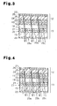
In Fig. 3, the area of the liquid crystal 17 in the
black display state is shown by vertical stripes. As shown
by arrows in Fig. 3, the ambient light entering the liquid
crystal panel 13 is reflected by the second electrode 26 of
the organic EL panel 12 at the area corresponding to the
liquid crystal sub-pixels other than those in the black
display state. The reflected light enters the liquid
crystal panel 13 from the organic EL panel 12, passes
through the regions 20a to 20c, and exits from the
substrate 15. An image is displayed on the liquid crystal
panel 13 with high quality using the bright ambient light
as the light source.
In the backlight mode of the simultaneous driving mode
for simultaneously driving the liquid crystal panel 13 and
the organic EL panel 12, all EL sub-pixels are maintained
in a light emitting state at the same brightness, and the
liquid crystal panel 13 is driven in the passive matrix
drive system. That is, the controller 33 provides a
command signal to the first electrode driver 29 and the
second electrode driver 30 to maintain the state in which
the same voltage is applied between all of the first
electrodes 24 and the second electrodes 26. Further, the
controller 33 provides a command signal to the scanning
electrode driver 31 and the transparent electrode driver 32
of the liquid crystal panel 13 to drive each scanning
electrode 21 and the transparent electrode 18 in the
passive matrix drive system.
As shown in Fig. 4, the ambient light entering the
liquid crystal panel 13 is reflected by the second
electrode 26 of_the organic EL panel 12 at the area
corresponding to the liquid crystal sub-pixels other than
those in the black display state. The reflected light
passes through the color filter 20 (regions 20a to 20c) and
exits from the substrate 15. Further, the organic
electroluminescence layer 25 of the organic EL panel 12
emits light (wide arrow). In the liquid crystal panel 13,
the light emitted from the organic electroluminescence
layer 25 is blocked at the area corresponding to the liquid
crystal sub-pixel in the black display state. At the area
corresponding to the liquid crystal sub-pixels other than
those in the black display state, the light emitted from
the organic electroluminescence layer 25 passes through the
regions 20a to 20c and exits from the substrate 15. Thus,
in a relatively dark environment such as during the night
or in a room with low illuminance, a color image is
displayed using the organic electroluminescence layer 25 of
the organic EL panel 12 as the main light source.
In the first synchronizing mode of the simultaneous
driving mode, the EL sub-pixels corresponding to the liquid
crystal sub-pixels in the black display state are in a non-light
emitting state and the other EL sub-pixels emit light
at the same brightness. Further, the controller 33
provides the command signal to the scanning electrode
driver 31 and the transparent electrode driver 32 of the
liquid crystal panel 13 to drive each scanning electrode 21
and the transparent electrode 18 in the passive matrix
drive system. The example shown in Fig. 5 differs from the
backlight mode in that the organic electroluminescence
layer 25 of the organic EL panel 12 does not emit light at
the area corresponding to the liquid crystal sub-pixel in
the black display state. The first synchronizing mode
consumes less power than the backlight mode. In Fig. 5,
the narrow arrows indicate ambient light, and the wide
arrows indicate the light emitted from the organic
electroluminescence layer 25. The wide arrows also
indicate the reflection of the light emitted from the
organic electroluminescence layer 25 and reflected by the
second electrode 26.
The second synchronizing mode of the simultaneous
driving mode is similar to the first synchronizing mode in
that the EL sub-pixel corresponding to the liquid crystal
sub-pixel in the black display state is in a non-luminescent
state. However, the emitting state (brightness
of the organic electroluminescence layer 25) of the EL sub-pixel
is adjusted in accordance with the amount of light
transmission (gradation display of the liquid crystal panel
13) of the liquid crystal sub-pixels. That is, the EL sub-pixels
corresponding to the liquid crystal sub-pixels
having a large amount of light transmission have high
brightness, and the EL sub-pixels corresponding to the
liquid crystal sub-pixels having a small amount of light
transmission has low brightness. Therefore, in the second
synchronizing mode, the image is displayed with higher
contrast, and the power consumption is reduced compared to
the first synchronizing mode.
The first preferred embodiment of the present
invention has the following advantages.
It should be understood that the present invention may
be embodied in the following forms.
The second electrode 26 does not have to function as
the light reflecting portion. In this case, for example,
referring to Fig. 6, the second electrode 26 is made of a
transparent electrically conductive material (e.g., ITO),
and a reflecting member 35 functioning as the light
reflecting portion is arranged on the second electrode 26
facing away from the liquid crystal panel 13. In the
example shown in Fig. 6, the passivation film 27 is
transparent, and the reflecting member 35 is located on the
outer side of the passivation film 27. The reflecting
member 35 is a film made of metal, such as chromium. Even
in such a case, after the organic EL panel 12 and the
liquid crystal panel 13 are separately manufactured, the
two panels are combined to form the display 11. Further,
compared to a configuration in which one of the electrodes
(second electrode 26) arranged to sandwich the organic
electroluminescence layer 25 also functions as the light
reflecting portion, the degree of freedom in selecting the
material forming the light reflecting portion of high
reflectivity is high.
The light reflecting portion needs only to be arranged
on the side of the liquid crystal panel 13 that is opposite
to the organic EL panel 12. Thus, the light reflecting
portion may be arranged on the same side as the liquid
crystal panel 13 with respect to the luminescent layer of
the organic EL panel 12. For example, a light reflecting
portion (e.g., half mirror) that reflects light directed
from the liquid crystal panel 13 towards the organic EL
panel 12 but transmits the light directed from the organic
EL panel 12 side towards the liquid crystal panel 13 may be
arranged between the organic EL panel 12 and the liquid
crystal panel. In such a case as well, the ambient light
reflected at the light reflecting portion is used as the
light source for the liquid crystal panel 13, and the light
emitted from the organic EL panel 12 passes through the
light reflecting portion and is used as the light source
for the liquid crystal panel 13.
The selection of the display mode of the display 11
does not have to be based on the command signal input to
the controller 33 through the operation of the input device
34 by the user of the display 11. For example, a sensor
for measuring the luminosity outside the display 11 (more
preferably, the display surface) may be employed. If the
luminosity is greater than or equal to a threshold value,
an image is displayed in the liquid crystal display mode.
If the luminosity is less than the threshold value, an
image is displayed in one of the simultaneous driving
modes. Further, a plurality of thresholds may be used so
that the brightness of the organic EL panel 12 when used as
the backlight mode is set in a plurality of stages
depending on the amount of the luminosity detected by the
sensor. In this case, an image is displayed using power
efficiently even if the user does not determine the display
mode.
In the configuration described above in which the
display mode is automatically set before the display mode
is input from the input device 34, the display mode may be
input from the input device 34 to display an image in
accordance with the display mode input to the input device
34. Further, a configuration for determining whether to
give priority to the display mode input through the input
device 34 or to the display mode automatically set by the
controller 33 may be provided. For example, a selector may
be provided. In this case, the degree of freedom in
selecting the display mode is higher.
The first electrode 24 arranged on the substrate 23
may be the cathode, and the second electrode 26 may be the
anode. In this case, the configuration of the organic
electroluminescence layer 25 is also changed. In this
case, the organic electroluminescence layer 25 may include
from the side closer to the first electrode 24 three
layers, including an electron injection layer, a
luminescent layer, and a hole injection layer.
Alternatively, the organic electroluminescence layer 25 may
include, five layers, an electron injection layer, an
electron transport layer, a luminescent layer, a hole
transport layer and a hole injection layer.
The first electrode 24, the second electrode 26, and
each layer of the organic electroluminescence layer 25 may
be formed through a known thin-film manufacturing method
using a known material. The material of the anode may be,
in addition to ITO, IZO, zinc aluminum oxide and the like.
The material of the cathode may be, in addition to chromium
and aluminum, an alloy containing more than one or more
metals selected from Li, Mg, Ca, Sr, La, Ce, Er, Eu, Sc, Y,
Yb, etc., which have a low work function, and a stable
metal element of Ag, Al, Cu, etc. More specifically, the
alloys of MgAg, AlLi, CuLi, etc. may be used.
The hole transport layer may be formed from low
molecular weight materials including metal phthalocyanines,
such as copper phthalocyanine and tetra (t-butyl) copper
phthalocyanine, metal-free phthalocyanines, quinacridones,
and aromatic tertiary amines, such as 1,1-bis(4-di-p-tolylaminophenyl)cyclohexane,
and N,N'-diphenyl-N,N'-bis-(3-methylphenyl)-1,1'-biphenyl-4,4'-diamine,
N,N'-di(1-naphtyl)-N,N'-diphenyl-1,1'-biphenyl-4,4'--diamine;
polymer
materials, such as polythiophene and polyaniline;
polythiophene oligomer materials; and other materials that
are known to be used to form the hole transport layer.
The luminescent layer may be formed from low molecular
weight materials such as 9-10-diaryl anthracene
derivatives, pyrene, coronene, perylene, rubrene, 1,1,4,4-tetraphenylbutadiene,
tris(8-quinolinolate) aluminum,
tris(4-methyl-8-quinoliate) aluminum, bis(8-quinolinolate)
zinc, tris(4-methyl-5-trifluoromethyl-8-quinolinolate)
aluminum, bis(2-methyl-5-trifluorormethyly-8-quinolinolate)
[4-(4-cyanophenyl)phenolate] aluminum, bis(2-methyl-5-cyano-8-quinolinolate)[4-(4-cyanophenyl)phenolate]
aluminum, tris(8-quinolinolate) scandium, bis[8-(p-tosyl)aminoquinoline]
zinc or cadmium, 1,2,3,4-tetraphenylcyclopentadiene,
pentaphenylcyclopentadiene,
poly-2,5-diheptyloxy-p-phenylene vinylene, fluorescent
coumarins, fluorescent perylenes, fluorescent pyrans,
fluorescent anthrons, fluorescent porphyrins, fluorescent
quinacridones, N,N'-dialkyl-replaced fluorescent
quinacridones, fluorescent naphthalimides, N,N'-diaryl-replaced
fluorescent pyrroropyrroles; polymer materials,
such as polyfluorene, poly p-phenylene vinylene, and
polythiophene; and other materials that are known to be
used to form the luminescent layer.
The electron transport layer may be formed from 2-(4-biphenylyl)-5-(4-t-butylphenyl)-1,3,4-oxadiazole;
2,5-bis(1-naphthyl)-1,3,4-oxadiazole
and oxadiazole
derivatives; bis(10-hydroxybenzo[h]quinolinolato).beryllium;
and triazoles.
Instead of using a transparent material that is
electrically conductive, the first electrode 24 and the
second electrode 26 may be formed from a transparent and
extremely thin metal layer. The phrase "extremely thin"
refers to the thickness being less than 50nm, and
preferably, within the range of 0.5 to 20nm. Further, the
first electrode 24 and the second electrode 26 may have a
configuration in which such metal layer and the known
transparent electrode, made of, for example, ITO, are
superimposed.
The white luminescent layer constituting the organic
electroluminescence layer 25 may be a luminescent layer
having a configuration in which a plurality of luminescent
layers including different light-emitting colors are
superimposed or a configuration in which light-emitting
material containing a plurality of light-emitting centers
in a single luminescent layer may be used. The employment
of the configuration in which the light-emitting material
containing a plurality of light-emitting centers in a
single luminescent layer reduces the number of applications
required to form the luminescent layer.
The organic EL panel 12 is not limited to the bottom
emission type in which light from the organic
electroluminescence layer 25 exits from the substrate 23.
The organic EL panel 12 may, for example, be a top emission
type in which light exits from the side facing away from
the substrate 23, and the organic EL panel 12 and the
liquid crystal panel 13 may be joined with each other so
that the substrate 23 is positioned on the opposite side of
the liquid crystal panel 13.
The liquid crystal panel 13 does not have to be
normally white and may be normally black. In this case,
when displaying an image on the organic EL panel 12 using
the EL panel driving means, the amount of power consumption
for maintaining the liquid crystal panel 13 in the black
display state is lower than in the normally white mode.
The organic EL panel 12 and the liquid crystal panel
13 are not limited to the passive matrix drive system. For
example, the liquid crystal panel 13 may employ the passive
matrix drive system, and the organic EL panel 12 may employ
the active matrix drive system. Alternatively, both the
organic EL panel 12 and the liquid crystal panel 13 may
employ the active matrix drive system. In the active
matrix drive. system, an active element is arranged for each
sub-pixel, and voltage is either applied or not applied to
an electrode for each sub-pixel. On the other hand, in the
passive matrix drive system, the adjustment of the
transmissivity of the liquid crystal 17 and the brightness
of the organic electroluminescence layer 25 are carried out
for each scanning electrode 21 or for each first electrode
24. Therefore, when adjusting the transmissivity of the
liquid crystal 17 for each sub-pixel or adjusting the
brightness of the organic electroluminescence layer 25, the
active matrix drive system must be used.
When simultaneously driving the liquid crystal.panel
13 and the organic EL panel 12, the brightness of the EL
sub-pixels corresponding to the liquid crystal sub-pixels
is continuously changed in accordance with the
transmittance state of the liquid crystal sub-pixels.
However, the brightness may be changed in a stepped manner.
For example, the transmission state of the liquid crystal
sub-pixels may be divided into a plurality of stages, and
the brightness of each EL sub-pixel may be set in advance
in accordance with each stage. Thus, the EL sub-pixel
emits light at the brightness set in accordance with the
transmission state of the liquid crystal sub-pixel. In
this case, the contrast is higher than in the first
synchronizing mode, and the control is easier than in the
second synchronizing mode.
The gradation display method of the display 11 is not
limited to the method of adjusting the brightness and the
transmissivity with respect to both the EL sub-pixel and
the liquid sub-pixel. Other methods include, (1) a method
of maximizing the transmissivity of the liquid crystal sub-pixel
and adjusting the brightness of the EL sub-pixel, (2)
a method of emitting the EL sub-pixel at the maximum
brightness and adjusting the transmissivity of the liquid
crystal sub-pixel, and (3) a method of emitting light from
all of the EL sub-pixels at the maximum brightness to use
the light as a backlight, and adjusting the transmissivity
of the liquid crystal sub-pixel.
More generally, the gradation process is performed
according to one of the following methods.
- A method for performing the gradation process by
controlling the amount of light transmission of each liquid
crystal sub-pixel. In this case, each EL sub-pixel may
emit light at the same brightness.
- A method for performing the gradation process by
controlling the brightness of the light emitted from each
EL sub-pixel.
Further, an image may be displayed on the liquid
crystal panel, and the entire surface of the
electroluminescence panel may emit light.
The passivation film 27 constituting the organic EL
panel 12 does not necessarily have to be made of silicon
nitride and may be made of other materials that is
transparent and that does not permeate moisture and gas
such as oxygen. For example, silicon oxide and diamond-like
carbon may be used. Further, the passivation film 27
is not limited to a film formed by the deposition of
silicon nitride, silicon oxide, diamond-like carbon and the
like, and may also be formed by applying, for example,
polysilazane so as to form a coating.
A sealing can (sealing cover) may be used instead of
the passivation film 27 to protect the organic
electroluminescence layer 25 from external moisture and
oxygen. For example, a cover made of light transmissive
glass may be bonded to the substrate 23 with a sealing
agent so as to cover the color filter 20, the first
electrode 24, the organic electroluminescence layer 25, and
the second electrode 26.
The liquid crystal sub-pixels and the EL sub-pixels do
not necessarily have to be arranged in parallel strips, and
may be arranged in a honeycomb manner. In this case, the
regions 20a and 20c are also arranged in the same manner.
The color filter 20 does not necessarily have to
include the regions 20a, 20b, and 20c for the three colors
of red (R), green (G), and blue (B) that are arranged in
parallel strips. For example, among the regions 20a, 20b,
and 20c of the three colors of R, G, and B, a filter of the
same color may be arranged diagonally or in a mosaic
arrangement, or the regions 20a, 20b, and 20c of the three
colors of R, G, B may be arranged in a triangular shape or
in a delta arrangement. The shape of each filter is not
limited to a square and may be a hexagon.
Only the first synchronizing mode or only the second
synchronizing mode may be used as the synchronizing mode
for driving the organic EL panel 12 and the liquid crystal
panel 13 in the synchronizing state. In this case, control
is easier if only the first synchronizing mode is used.
Only the backlight mode may be used as the
simultaneous driving mode and the synchronizing modes may
be eliminated. In the backlight mode, the brightness of
the EL sub-pixels may be selected from a plurality of
stages. For example, the brightness of the EL sub-pixels
may be selected from the three steps of high brightness,
medium brightness, and low brightness. In this case, the
user may select the brightness in accordance with the
surrounding illuminance.
The liquid crystal panel 13 may be semi-transmissive.
The inorganic electroluminescence panel (inorganic EL
panel) may be used as the electroluminescence panel in
place of the organic EL panel 12. In this case, the
voltage applied to emit light from the EL element is higher
than the organic EL panel 12. However, the merits of a
display using the EL element and the merits of the liquid
crystal display enable the display of a color image in
accordance with the environment and the purpose of use.
It should be apparent to those skilled in the art that
the present invention may be embodied in many other
specific forms without departing from the spirit or scope
of the invention. Therefore, the present invention is not
to be limited to the details given herein, but may be
modified within the scope and equivalence of the appended
claims.
A display for displaying a color image in accordance.
with the surrounding environment. The display includes a
transmissive liquid crystal panel (13) and a color filter
(20) arranged on an organic EL panel (12). The organic EL
panel includes EL sub-pixels, arranged on the opposite side
of a display surface of the liquid crystal panel, which
emit white light in accordance with each liquid crystal
sub-pixel of the liquid crystal panel. The organic EL
panel further includes a light reflecting portion (26; 35)
for reflecting light entering from the liquid crystal panel
towards the liquid crystal panel. The display includes a
first driver (31, 32) for displaying an image on the liquid
crystal panel, a second driver (29, 30) for displaying an
image on the organic EL panel, and a controller (33) for
determining whether to use the first driver and whether to
use the second driver to display an image.