EP1496315A1 - Air conditioner, remote controller, and ultrasonic wave generating unit - Google Patents
Air conditioner, remote controller, and ultrasonic wave generating unit Download PDFInfo
- Publication number
- EP1496315A1 EP1496315A1 EP03705406A EP03705406A EP1496315A1 EP 1496315 A1 EP1496315 A1 EP 1496315A1 EP 03705406 A EP03705406 A EP 03705406A EP 03705406 A EP03705406 A EP 03705406A EP 1496315 A1 EP1496315 A1 EP 1496315A1
- Authority
- EP
- European Patent Office
- Prior art keywords
- air conditioner
- ultrasonic wave
- ultrasonic waves
- ultrasonic
- wave generator
- Prior art date
- Legal status (The legal status is an assumption and is not a legal conclusion. Google has not performed a legal analysis and makes no representation as to the accuracy of the status listed.)
- Withdrawn
Links
Images






Classifications
-
- A—HUMAN NECESSITIES
- A61—MEDICAL OR VETERINARY SCIENCE; HYGIENE
- A61M—DEVICES FOR INTRODUCING MEDIA INTO, OR ONTO, THE BODY; DEVICES FOR TRANSDUCING BODY MEDIA OR FOR TAKING MEDIA FROM THE BODY; DEVICES FOR PRODUCING OR ENDING SLEEP OR STUPOR
- A61M21/00—Other devices or methods to cause a change in the state of consciousness; Devices for producing or ending sleep by mechanical, optical, or acoustical means, e.g. for hypnosis
-
- F—MECHANICAL ENGINEERING; LIGHTING; HEATING; WEAPONS; BLASTING
- F24—HEATING; RANGES; VENTILATING
- F24F—AIR-CONDITIONING; AIR-HUMIDIFICATION; VENTILATION; USE OF AIR CURRENTS FOR SCREENING
- F24F11/00—Control or safety arrangements
- F24F11/50—Control or safety arrangements characterised by user interfaces or communication
- F24F11/56—Remote control
- F24F11/59—Remote control for presetting
-
- F—MECHANICAL ENGINEERING; LIGHTING; HEATING; WEAPONS; BLASTING
- F24—HEATING; RANGES; VENTILATING
- F24F—AIR-CONDITIONING; AIR-HUMIDIFICATION; VENTILATION; USE OF AIR CURRENTS FOR SCREENING
- F24F11/00—Control or safety arrangements
- F24F11/70—Control systems characterised by their outputs; Constructional details thereof
-
- F—MECHANICAL ENGINEERING; LIGHTING; HEATING; WEAPONS; BLASTING
- F24—HEATING; RANGES; VENTILATING
- F24F—AIR-CONDITIONING; AIR-HUMIDIFICATION; VENTILATION; USE OF AIR CURRENTS FOR SCREENING
- F24F11/00—Control or safety arrangements
- F24F11/70—Control systems characterised by their outputs; Constructional details thereof
- F24F11/72—Control systems characterised by their outputs; Constructional details thereof for controlling the supply of treated air, e.g. its pressure
- F24F11/74—Control systems characterised by their outputs; Constructional details thereof for controlling the supply of treated air, e.g. its pressure for controlling air flow rate or air velocity
-
- F—MECHANICAL ENGINEERING; LIGHTING; HEATING; WEAPONS; BLASTING
- F24—HEATING; RANGES; VENTILATING
- F24F—AIR-CONDITIONING; AIR-HUMIDIFICATION; VENTILATION; USE OF AIR CURRENTS FOR SCREENING
- F24F13/00—Details common to, or for air-conditioning, air-humidification, ventilation or use of air currents for screening
- F24F13/24—Means for preventing or suppressing noise
-
- A—HUMAN NECESSITIES
- A61—MEDICAL OR VETERINARY SCIENCE; HYGIENE
- A61M—DEVICES FOR INTRODUCING MEDIA INTO, OR ONTO, THE BODY; DEVICES FOR TRANSDUCING BODY MEDIA OR FOR TAKING MEDIA FROM THE BODY; DEVICES FOR PRODUCING OR ENDING SLEEP OR STUPOR
- A61M21/00—Other devices or methods to cause a change in the state of consciousness; Devices for producing or ending sleep by mechanical, optical, or acoustical means, e.g. for hypnosis
- A61M2021/0005—Other devices or methods to cause a change in the state of consciousness; Devices for producing or ending sleep by mechanical, optical, or acoustical means, e.g. for hypnosis by the use of a particular sense, or stimulus
- A61M2021/0027—Other devices or methods to cause a change in the state of consciousness; Devices for producing or ending sleep by mechanical, optical, or acoustical means, e.g. for hypnosis by the use of a particular sense, or stimulus by the hearing sense
- A61M2021/0038—Other devices or methods to cause a change in the state of consciousness; Devices for producing or ending sleep by mechanical, optical, or acoustical means, e.g. for hypnosis by the use of a particular sense, or stimulus by the hearing sense ultrasonic
-
- F—MECHANICAL ENGINEERING; LIGHTING; HEATING; WEAPONS; BLASTING
- F24—HEATING; RANGES; VENTILATING
- F24F—AIR-CONDITIONING; AIR-HUMIDIFICATION; VENTILATION; USE OF AIR CURRENTS FOR SCREENING
- F24F13/00—Details common to, or for air-conditioning, air-humidification, ventilation or use of air currents for screening
- F24F13/24—Means for preventing or suppressing noise
- F24F2013/247—Active noise-suppression
Definitions
- the present invention relates to an air conditioner configured to deliver conditioned air into a room, a remote controller configured to send control signals to an air conditioner, and an ultrasonic wave generating unit configured to be mounted to an air conditioner.
- An air conditioner serves to improve the comfort of room occupants by delivering conditioned air into the room.
- the heating/cooling units typically called “air conditioners” can maintain a room temperature that is comfortable for room occupants by delivering cool air or warm air into the room.
- air cleaners another type of air conditioner, serve to keep the air inside a room clean and improve the comfort of room occupants by removing dust, particles, and other contaminants from air drawn into the air cleaner and delivering clean air into the room.
- air conditioners provided with such functions as humidity control, odor removal, and negative ion generation are promoting the comfort of room occupants.
- the object of the present invention is to provide an air conditioner, a remote controller, and an ultrasonic wave generating unit that are capable of improving the feeling of comfort of room occupants in a room where the air conditioner is used.
- the invention described in claim 1 is an air conditioner that is configured to blow conditioned air into a room and is equipped with an ultrasonic wave generator and a control unit.
- the ultrasonic wave generator is configured to generate ultrasonic waves having frequencies ranging from 20 kHz to 100 kHz.
- the control unit is configured to control the ultrasonic wave generator such that the ultrasonic waves overlap with the air blowing sound of the air conditioner.
- an ultrasonic wave generator is used to generate ultrasonic waves having frequencies ranging from 20 kHz to 100 kHz in such a manner that the ultrasonic waves overlap with the blowing sound of the air conditioner.
- the sound that reaches the ears of a room occupant includes the audible blowing sound of the air conditioner and the high-frequency ultrasonic waves having frequencies of 20 kHz and higher.
- a room occupant exposed to this sound will experience improved comfort due to the hypersonic effect.
- the attenuation of ultrasonic waves increases as the frequency increases, ultrasonic waves at frequencies exceeding 100 kHz do not easily reach room occupants.
- the present invention is contrived such that the ultrasonic waves are generated at frequencies ranging from 20 kHz to 100 kHz, the ultrasonic waves can reach the room occupants and can thus impart the hypersonic effect to the room occupants.
- an air conditioner in accordance with claim 1 can improve the comfort of room occupants.
- the invention described in claim 2 is an air conditioner as described in claim 1, wherein the control unit executes control in such a manner that a characteristic of the ultrasonic waves fluctuates.
- the ultrasonic wave characteristics mentioned in this invention include the frequency, the sound pressure, and the generation time.
- the characteristics of the ultrasonic waves generated by the ultrasonic wave generator are made to fluctuate and the comfort of the room occupants is improved due to the effect of the fluctuation.
- the invention described in claim 3 is an air conditioner as described in claim 2, wherein the control unit executes control in such a manner that the flow rate or flow speed of the air blown into the room fluctuates and a characteristic of the ultrasonic waves fluctuates at approximately the same cyclical frequency as the fluctuation of the blowing sound of the air conditioner.
- the control unit can be configured to make the ultrasonic waves fluctuate in an active manner or in a passive manner using the sound wave propagation environment, which varies depending on the flow rate or flow speed of the air blown into the room.
- the invention described in claim 4 is an air conditioner as described in claim 2 or 3, wherein the characteristic is the frequency of the ultrasonic waves.
- the frequency of the ultrasonic waves generated by the ultrasonic wave generator is made to fluctuate and the comfort of the room occupants is improved due to the effect of the fluctuation.
- the invention described in claim 5 is an air conditioner as described in claim 4, wherein the control unit executes control in such a manner that the frequency of the ultrasonic waves changes at intervals of 1 millisecond, 1 second, or an amount of time between 1 millisecond and 1 second.
- Sounds in the natural world include ultrasonic wave components in various frequency bands and these ultrasonic wave components reach the ear simultaneously.
- a feasible method of creating such a state artificially is to use a plurality of ultrasonic wave generators to generate ultrasonic waves in various frequency bands simultaneously, but this method is expensive because it requires the use of multiple ultrasonic wave generators.
- the interval is shorter than 1 millisecond, it will be difficult to compose a pulse and if the interval is longer than 1 second, the timing at which the frequency of the ultrasonic waves is changed will become slow and it will be difficult to approximate the kind of fluctuation that occurs in the natural world.
- the invention described in claim 6 is an air conditioner as described in claim 2 or 3, wherein the characteristic is the sound pressure of the ultrasonic waves.
- the sound pressure of the ultrasonic waves generated by the ultrasonic wave generator is made to fluctuate and the comfort of the room occupants is improved due to the effect of the fluctuation.
- the invention described in claim 7 is an air conditioner as described in claim 6, wherein the ultrasonic wave generator is equipped with an oscillator, an amplifier, and a piezoelectric element.
- the oscillator is configured to generate a signal having an ultrasonic frequency.
- the amplifier is configured to amplify the voltage of the signal.
- the piezoelectric element is configured to convert the amplified signal outputted from the amplifier into ultrasonic waves.
- the controller varies the amplification factor of the amplifier.
- the sound pressure fluctuates because the controller varies the amplification factor of the amplifier.
- the sound pressure of the ultrasonic waves generated by the ultrasonic wave generator is made to fluctuate and the comfort of the room occupants is improved due to the effect of the fluctuation.
- the invention described in claim 8 is an air conditioner as described in claim 4 or 5, wherein the ultrasonic wave generator is equipped with a piezoelectric element.
- the piezoelectric element has a plurality of sound pressure peaks within the frequency band where the frequency of the ultrasonic waves is made to fluctuate by the control unit.
- the piezoelectric element provided in the ultrasonic wave generator has a plurality of sound pressure peaks within the frequency band where the frequency of the ultrasonic waves is made to fluctuate by the control unit. Consequently, if the frequency of the ultrasonic waves varies through one round trip across the frequency band, the sound pressure of the ultrasonic waves will also change repeatedly by a number of times equal to the number of peaks. In other words, the sound pressure can be varied several times by merely varying the frequency by a small amount. Thus, the sound pressure can be easily made to fluctuate.
- the invention described in claim 9 is an air conditioner as described in any one of claims 2 to 8, wherein the controller has a first control unit and a second control unit.
- the first control unit controls the air conditioning functions of the air conditioner.
- the second control unit controls the fluctuation of the ultrasonic waves of the ultrasonic wave generator.
- the fluctuation of the ultrasonic waves of the ultrasonic wave generator is controlled by a second control unit that is separate from the first control unit that controls the air conditioning functions of the air conditioner. Consequently, the control of the ultrasonic wave fluctuation can be prevented from increasing the load imposed on the first controller used to control the air conditioning functions.
- the invention described in claim 10 is an air conditioner as described in any one of claims 1 to 9, wherein the ultrasonic wave generator has a wave transmitter configured to transmit ultrasonic waves toward the inside of the room.
- the wave transmitter is arranged in a position where it has access to the space inside the room.
- Ultrasonic waves do not easily penetrate matter and are readily reflected from the surfaces of matter. Consequently, if the wave transmitter used to transmit ultrasonic waves toward the inside of a room is located deep inside the air conditioner, the components of the air conditioner will act as obstacles causing the ultrasonic waves to attenuate easily. As a result, it will be difficult for the ultrasonic waves to reach the room occupants.
- wave transmitter is arranged in a position where it has access to the space inside the room and the ultrasonic waves are not likely to be hindered by an obstacle before reaching the room occupants.
- the ultrasonic waves easily reach the room occupants.
- the invention described in claim 11 is an air conditioner as described in any one of claims 1 to 9, wherein the air conditioner is provided with a casing having a front face part that covers the front face of the air conditioner and the ultrasonic wave generator has a wave transmitter configured to transmit ultrasonic waves toward the inside of the room.
- the wave transmitter is arranged near the rear side of the front face part.
- the wave transmitter used to transmit ultrasonic waves toward the inside of the room is arranged near the rear side of the front face part.
- the wave transmitter is arranged in one of the more frontward positions inside the air conditioner.
- the invention described in claim 12 is an air conditioner as described in any one of claims 1 to 9, wherein the air conditioner is further provided with a casing and an indoor heat exchanger.
- the casing has a front face part that covers the front face of the air conditioner.
- the indoor heat exchanger exchanges heat with the air inside the room.
- the ultrasonic wave generator has a wave transmitter configured to transmit ultrasonic waves toward the inside of the room. The wave transmitter is arranged between the front face part and the heat exchanger.
- the wave transmitter used to transmit ultrasonic waves toward the inside of the room is arranged between the front face part and the heat exchanger.
- the wave transmitter is positioned farther toward the front than the heat exchanger and is therefore arranged in a position even closer to the front of the air conditioner.
- the invention described in claim 13 is an air conditioner as described in any one of claims 10 to 12, wherein the air conditioner is further provided with an outlet vent through which conditioned air is blown out.
- the wave transmitter is arranged near the outlet vent.
- the wave transmitter is arranged near the outlet vent, the ultrasonic waves can reach the occupants easily and are not likely to be hindered by an obstacle before reaching the room occupants. Additionally, since the ultrasonic waves are generated in the vicinity of the outlet vent where the blowing sound of the air conditioner occurs, the ultrasonic waves readily overlap with the blowing sound.
- the invention described in claim 14 is a remote controller configured to send control signals to an air conditioner as described in any one of claims 1 to 13, the remote controller being provided with a control selecting means configured to allow a user to select how the ultrasonic wave generator will be controlled.
- the remote controller is provided with a control selecting means configured to allow a user to select how the ultrasonic wave generator will be controlled, a room occupant who wishes to operate the ultrasonic wave generator can easily do so by using the control selecting means.
- the invention described in claim 15 is a remote controller configured to send control signals to an air conditioner that is configured as described in any one of claims 2 to 13 and also provided with a memory unit storing a plurality of patterns for fluctuation of the ultrasonic waves and pattern identification data corresponding to each of the patterns, the remote controller being provided with a signal transmitter and a fluctuation pattern selecting means.
- the fluctuation pattern selecting means allows a user to select the pattern.
- the signal transmitter transmits pattern recognition data corresponding to the pattern selected using the fluctuation pattern selecting means.
- the signal transmitter transmits pattern recognition data corresponding to the selected ultrasonic wave fluctuation pattern.
- the volume of data in the transmitted signal is smaller than a case in which the transmitted signal contains data expressing the entire ultrasonic wave fluctuation pattern.
- the invention described in claim 16 is an ultrasonic wave generating unit configured to be mounted to an air conditioner that is configured to blow conditioned air into a room, the ultrasonic wave generating unit being equipped with an ultrasonic wave generator and a control unit.
- the ultrasonic wave generator is configured to generate ultrasonic waves having frequencies ranging from 20 kHz to 100 kHz.
- the control unit is configured to control the ultrasonic wave generator such that the ultrasonic waves overlap with the air blowing sound of the air conditioner. It is also acceptable for the control unit to be built into the ultrasonic wave generator.
- This ultrasonic wave generating unit is a separate unit from the air conditioner and can be mounted to an existing air conditioner.
- this ultrasonic wave generating unit makes it possible to add an ultrasonic wave generating function to an existing air conditioner inexpensively.
- the air conditioner described in claim 17 is an air conditioner as described in claims 7 or 8, wherein the ultrasonic wave generator is further provided with an audible signal oscillator configured to generate a signal having an audible frequency.
- the audible signal oscillator can be the same device as the oscillator used to generate ultrasonic frequencies or it can be a separate device.
- the piezoelectric element used to output the ultrasonic waves can be inspected by generating a signal having an audible frequency and sending the signal to the piezoelectric element.
- advanced ultrasonic inspection equipment is not required to inspect the ultrasonic wave generator. This feature enables the equipment used for mass production to be simplified.
- Figure 1 is a diagrammatic view showing the external appearance of an air conditioner.
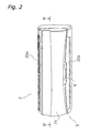
- Figure 2 is a diagrammatic view showing the external appearance of an indoor unit.
- FIG. 3 is a block diagram showing the constituent features of an ultrasonic wave generator.
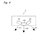
- Figure 4 is a view showing the arrangement of the piezoelectric oscillators.
- Figure 5 is a graph showing a plot of the sound pressure versus frequency characteristic of a piezoelectric oscillator.
- Figure 6 is a graph showing a plot of the sound pressure versus frequency characteristic of a piezoelectric oscillator.
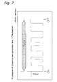
- Figure 7 is a graph illustrating fluctuation of the length of time during which ultrasonic waves are generated and the length of the intervals between times when ultrasonic waves are generated.
- Figure 8 is a diagrammatic view showing the external appearance of an remote controller.
- Figure 9 is a frontal view showing the external appearance of the indoor unit of an air conditioner in accordance with a second embodiment.
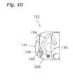
- Figure 10 is a right side view showing the external appearance of the indoor unit of an air conditioner in accordance with the second embodiment.
- Figure 1 shows an air conditioner 1 that employs an embodiment of the present invention.
- the air conditioner 1 is a device configured to condition the air inside a room by blowing into the room air that has been conditioned by being heated or cooled and humidified or dehumidified.
- the air conditioner 1 includes an indoor unit 2 that is mounted to a wall or the like inside the room and an outdoor unit 3 that is installed outdoors.
- the outdoor unit 3 comprises an outdoor heat exchanger, an outdoor fan, an electronic component box, and other components (not shown) all enclosed in a casing.
- the indoor unit 2 includes an indoor heat exchanger, an indoor fan, a fan motor for driving the indoor fan, etc. (not shown), and the indoor heat exchanger and outdoor heat exchanger are connected by refrigerant piping 4 so as to form a refrigerant circuit.
- the indoor unit 2 is equipped with a control unit 9 and an ultrasonic wave generator 6 (see Figure 3).
- the control unit 9 controls such air conditioning functions as heating, cooling, and humidifying/dehumidifying and also controls the ultrasonic wave generating function. It controls the ultrasonic wave generator 6 in such a manner as to cause the ultrasonic waves generated by the ultrasonic wave generator 6 to overlap with the air blowing sound of the air conditioner 1.
- the control unit 9 comprises chiefly a main microcomputer 21 configured to control such air conditioning functions as heating, cooling, and humidifying/dehumidifying and an ultrasonic wave control microcomputer 60 configured to control the ultrasonic wave generator 6 (See Figure 3).
- FIG. 2 shows the external appearance of the indoor unit 2.
- the casing 5 of the indoor unit 2 comprises chiefly a front panel 20 that covers the top, bottom and sides of the indoor unit 2 from the front and a bottom frame (not shown) that is positioned toward the rear.
- a multitude of slit-shaped openings serving as intake vents 20a are provided in the top side of the front panel 20.
- An outlet vent 20b for discharging conditioned air is provided in a bottom front portion of the front panel 20.
- the ultrasonic wave generator 6 is provided above the outlet vent 20b in close proximity to the outlet vent 20b.
- the ultrasonic wave generator 6 is configured to generate ultrasonic waves having frequencies ranging from 20 kHz to 100 kHz.
- the constituent features of the ultrasonic wave generator 6 are shown in Figure 3.
- the ultrasonic wave generator 6 comprises chiefly the ultrasonic wave control microcomputer 60, an amplifier 61, a piezoelectric oscillator 62, and a memory 63 (discussed later).
- the ultrasonic wave control microcomputer 60 has an ultrasonic signal generating circuit 60a configured to generate signals at ultrasonic frequencies of 20 kHz and above.
- the ultrasonic wave control microcomputer 60 is connected to the main microcomputer 21 and turns the ultrasonic wave generating function on and off based on control instructions received from the main microcomputer 21.
- the main microcomputer 21 is connected to a fan motor 22, various sensors 23 (e.g., a room temperature sensor and a humidity sensor), an electronic component 30 of the outdoor unit 3, and an input port 24, etc. for receiving signals from a remote controller (discussed later).
- the main microcomputer 21 controls the heating, cooling, humidifying/dehumidifying, and other air conditioning functions of the air conditioner 1.
- the amplifier 61 is connected to the ultrasonic wave control microcomputer 60 and serves to amplify and output the voltage of the ultrasonic frequency signal it receives from the ultrasonic wave control microcomputer 60.
- the piezoelectric oscillator 62 is configured to convert the amplified signal outputted from the amplifier 61 into ultrasonic waves.
- the piezoelectric oscillator 62 has a sound emitting body that vibrates and generates sound waves when an AC voltage is applied thereto. When a voltage having an ultrasonic frequency is applied to the piezoelectric oscillator 62, the sound emitting body vibrates at the ultrasonic frequency and generates ultrasonic waves.
- the piezoelectric oscillator 62 is arranged above the outlet vent 20b of the indoor unit in such a manner that it faces into the room and sends the generated ultrasonic waves toward the inside the room.
- this ultrasonic wave generator 6 has a plurality of piezoelectric oscillators 62 arranged facing in different directions such that they are mounted at slightly different angles in a horizontal plane.
- Figure 4 is a simplified cross sectional view of the arrangement of the piezoelectric oscillators 62 taken along line IV-IV of indoor unit 2 shown in Figure 2.
- Ultrasonic waves have strong directionality and are thus difficult to spread over a wide area.
- by arranging the piezoelectric oscillators 62 to emit ultrasonic waves in the multiple directions indicated by arrows A1, A2, and A3 ultrasonic waves can be delivered to a wide area. It is also acceptable to angle the piezoelectric oscillators 62 in the vertical direction.
- the ultrasonic wave generator 6 is configured as a separate unit from the other devices of the air conditioner 1. More specifically, the ultrasonic wave generator 6 is physically separate from the air conditioner main unit 8, which includes the main microcomputer, and the ultrasonic wave control microcomputer 60 and the main microcomputer 21 are connected by a connector 80. The ultrasonic wave generating function of the ultrasonic wave generator 6 is turned on and off by the main microcomputer 21.
- the ultrasonic wave generator 6 is a separate unit, it can be retrofitted into an existing air conditioner that does not have an ultrasonic wave generating function, enabling an ultrasonic wave generating function to be added easily and inexpensively.
- the ultrasonic wave control microcomputer 60 also has an audible signal generating circuit 60b configured to generate a signal at an audible frequency.
- the ultrasonic wave control microcomputer 60 can switch between generation of a signal in the ultrasonic region and generation of a signal in the audible region based on a switching signal from the main microcomputer 21.
- the piezoelectric oscillator 62 can be inspected during production of the indoor unit 2 and/or the ultrasonic wave generator 6 by sending a signal having an audible frequency to the piezoelectric oscillator 62.
- advanced ultrasonic inspection equipment is not required to inspect the piezoelectric oscillator 62 and the inspection can be accomplished more easily.
- the equipment used for mass production of the indoor unit 2 and/or the ultrasonic wave generator 6 can be simplified, incorrect inspection results can be reduced, and the time required to complete the inspection can be shortened.
- the pulse of the human heart and other biological rhythms are generally undergoing 1/f fluctuations. While there are various fluctuations that take place in the natural world, it has been demonstrated that those fluctuations sharing the same 1/f quality as biological rhythms -- e.g., wind movements, the annual rings of trees, the flame of a candle, and the sound of waves -- impart a pleasant feeling to humans in terms of the senses of sight, hearing, and touch.
- l/f fluctuations are imparted to the flow rate or flow speed of the air blown out of the air conditioner 1 and l/f fluctuations are also imparted to a characteristic of the ultrasonic waves generated by the ultrasonic wave generator 6. The fluctuation of the characteristic of the ultrasonic waves is synchronized with the fluctuation of the air flow.
- the ultrasonic wave characteristics to which 1/f fluctuation is imparted include time, frequency, and sound pressure and the following means exist for controlling the fluctuation of these characteristics.
- ultrasonic wave components in various frequency bands can be emitted without using a plurality of ultrasonic wave generators 6 and a state that approximates the natural world (in which sounds of various different frequencies are mixed together) can be created inexpensively.
- a state that approximates the natural world in which sounds of various different frequencies are mixed together
- an aural environment that approximates a natural environment can be recreated indoors inexpensively and it is possible to make the room more pleasant for the occupants.
- timing at which the frequency is varied is shorter than 1 millisecond. If the timing is longer than 1 second, the timing at which the frequency of the ultrasonic waves is varied will become slow and it will be difficult to approximate a natural state.
- Such air conditioning functions as heating, cooling, and humidifying/dehumidifying and the ultrasonic wave generating function of the ultrasonic wave generator 6 can be controlled using a remote controller 7 configured to send control signals to the air conditioner 1.
- the remote controller 7 is provided with a remote controller main body 70, an output port 71, a liquid crystal display 72, and operating buttons 73.
- the output port 71 is provided on the upper end of the remote controller main body 70 and is configured to send control signals to an input port 24 provided on the air conditioner 1.
- the liquid crystal display 72 is provided on the front face of the remote controller 7.
- the liquid crystal display 72 is configured to display a screen indicating the content of button operations and a screen indicating such setting information as the temperature setting, the humidity setting, the fan speed setting, and the ultrasonic wave function setting.
- the operating buttons 73 are provided on the front face of the remote controller 7 below the liquid crystal display 72. An occupant can select the details of how the air conditioner main unit 8 and the ultrasonic wave generator 6 will be controlled by pressing the operating buttons 73.
- the operating buttons 73 comprise an ON/OFF button 73a, a cooling mode button 73b, a heating mode button 73c, a dehumidifying mode button 73d, a humidifying mode button 73e, arrow buttons 73f, and an ultrasonic wave treatment button 73g. An occupant can accomplish various operations by pressing these buttons. In particular, the ultrasonic wave generation function can be turned on and off by simply pressing the ultrasonic wave treatment button 73g.
- the remote controller 7 transmits pattern identification data corresponding to the selected pattern from the output port 71 to the indoor unit 2 of the air conditioner 1.
- a memory 63 that stores data for a plurality of ultrasonic wave fluctuation patterns and pattern identification data assigned to each pattern (See Figure 3).
- the remote controller 7 instead of transmitting a signal containing data expressing the entire selected ultrasonic wave fluctuation pattern, the remote controller 7 transmits pattern identification data corresponding to the selected ultrasonic wave fluctuation pattern.
- the volume of data in the transmitted signal is smaller than a case in which the transmitted signal contains data expressing the entire ultrasonic wave fluctuation pattern.
- remote controller 7 with a touch screen liquid crystal display wherewith various operations can be executed by touching the liquid crystal display at positions where the images of buttons are displayed instead of pressing operating buttons 73.
- Figures 9 and 10 show the external appearance of the indoor unit 102 of an air conditioner that employs a second embodiment of the present invention.
- Figure 9 is a frontal view of the indoor unit 102 and
- Figure 10 is a right-hand side view of the indoor unit 102.
- This indoor unit 102 is characterized by the arrangement of the ultrasonic wave generator 106 and the arrangement of the ultrasonic wave generator 106 will now be described.
- the other constituent features are the same as the indoor unit 2 of the air conditioner 1 of the first embodiment, the different reference numerals are used in the figures illustrating the second embodiment than are used for the same features in the figures illustrating the first embodiment.
- the front panel 120 of the indoor unit 102 has a front section 121 that covers the front of the indoor unit 102.
- an electronic component unit 103 is provided above but near the outlet vent 120b inside a lower portion of the front section 121.
- the electronic component unit 103 comprises printed circuit boards containing control circuits and an electronic component box housing the printed circuited boards and is elongated in the lengthwise direction of the indoor unit 102.
- the ultrasonic wave generator 106 is positioned in closely adjacent to the electronic component unit 103 and on the left side of the electronic component unit 103 in a frontal view.
- the ultrasonic wave generator 106 has a piezoelectric oscillator 162.
- the electronic component unit 103 and the ultrasonic wave generator 106 are arranged facing the back side of a lower portion of the front section 121 and between the lower portion of the front section 121 and the indoor heat exchanger 104.
- the ultrasonic wave generator 106 is also disposed in such an orientation that it emits the ultrasonic waves forward and slightly downward from the indoor unit 102.
- the indoor heat exchanger 104 is mounted in such a manner as to surround the frontal, upper, and upper rear portions of an indoor fan 105 that is arranged near the center of the indoor unit 102 in a side view.
- an ultrasonic wave generator 106 having a piezoelectric oscillator 162 configured to transmit ultrasonic waves into a room is arranged facing the back side of the front section 121.
- the piezoelectric oscillator 162 is arranged in one of the more frontward positions inside the air conditioner.
- Air conditioners are generally arranged such that the living space of the room is positioned in front of the air conditioner.
- the piezoelectric oscillator 162 is arranged in a position that is closer to the room occupants than any other component inside the indoor unit 102.
- the piezoelectric oscillator 162 Since the piezoelectric oscillator 162 is arranged farther forward than the heat exchanger 104, there are few objects (such as the heat exchanger 104) in front of the piezoelectric oscillator 162 that can obstruct the ultrasonic waves. In short, with this air conditioner, the ultrasonic waves can be made to reach the room occupants more plentifully.
- the comfort of room occupants can be improved by delivering to the occupants ultrasonic waves that are capable of imparting a hypersonic effect.
Landscapes
- Engineering & Computer Science (AREA)
- Health & Medical Sciences (AREA)
- Combustion & Propulsion (AREA)
- Mechanical Engineering (AREA)
- General Engineering & Computer Science (AREA)
- Chemical & Material Sciences (AREA)
- Physics & Mathematics (AREA)
- Psychology (AREA)
- Hematology (AREA)
- Acoustics & Sound (AREA)
- Veterinary Medicine (AREA)
- Anesthesiology (AREA)
- Biomedical Technology (AREA)
- Heart & Thoracic Surgery (AREA)
- Public Health (AREA)
- Life Sciences & Earth Sciences (AREA)
- Animal Behavior & Ethology (AREA)
- General Health & Medical Sciences (AREA)
- Human Computer Interaction (AREA)
- Fluid Mechanics (AREA)
- Air Conditioning Control Device (AREA)
Abstract
The object of the present invention is to provide an air conditioner, a remote controller, and an ultrasonic wave generating unit that are capable of improving the feeling of comfort of room occupants in a room where the air conditioner is used. The air conditioner (1) is an air conditioner that is configured to blow conditioned air into a room and is equipped with an ultrasonic wave generator (6) and a control unit (9). The ultrasonic wave generator (6) is configured to generate ultrasonic waves having frequencies ranging from 20 kHz to 100 kHz. The control unit (9) is configured to control the ultrasonic wave generator (6) such that the ultrasonic waves overlap with the air blowing sound of the air conditioner. <IMAGE>
Description
The present invention relates to an air conditioner configured to deliver conditioned
air into a room, a remote controller configured to send control signals to an air
conditioner, and an ultrasonic wave generating unit configured to be mounted to an air
conditioner.
An air conditioner serves to improve the comfort of room occupants by delivering
conditioned air into the room. For example, the heating/cooling units typically called
"air conditioners" can maintain a room temperature that is comfortable for room
occupants by delivering cool air or warm air into the room. Meanwhile, air cleaners,
another type of air conditioner, serve to keep the air inside a room clean and improve the
comfort of room occupants by removing dust, particles, and other contaminants from air
drawn into the air cleaner and delivering clean air into the room. Furthermore, in recent
years, air conditioners provided with such functions as humidity control, odor removal,
and negative ion generation are promoting the comfort of room occupants.
In recent years it has been reported that sounds containing high frequency
components exceeding the audible frequency range of the human ear, i.e., exceeding the
range from about 20 Hz to 20 kHz, exhibit such an effect (the "hypersonic effect") that
they improve the feeling of comfort of a person exposed to them more than sounds that
do not include such high frequencies. In particular, such findings have been reported in
the following document: Ohashi et al, "Hypersonic Effect," Technical Report of The
Institute of Electronics, Information, and Communication Engineers, sp 96 to 112 (1997-02).
That document reports that even though individual frequencies in excess of 26 kHz
cannot be heard by the human ear, sounds containing frequency components in excess of
26 kHz increase the power spectra of the alpha waves of the brain (measured by
electroencephalogram (EEG)) by an amount that is statistically significant in comparison
with sounds that do not contain such high-frequency components. Such high-frequency
components also have the effect of causing the audible sounds with which they are
intermingled to be perceived in a more pleasant manner by the listener. Alpha waves
are known as the brain waves whose activity increases when a person closes his or her
eyes and relaxes, and it is believed that the hypersonic effect causes a person to
experience an increased feeling of comfort.
Sounds that contain high-frequency components that exceed the audible frequency
range of the human ear in excess of 20 kHz occur often in natural environments, but such
sounds are almost non-existent in indoor spaces that are surrounded by concrete and the
like. Thus, in the indoor spaces where the above-mentioned air conditioners are used,
such high-frequency containing sounds are almost non-existent and there is little hope of
improving comfort by means of the hypersonic effect.
The object of the present invention is to provide an air conditioner, a remote
controller, and an ultrasonic wave generating unit that are capable of improving the
feeling of comfort of room occupants in a room where the air conditioner is used.
The invention described in claim 1 is an air conditioner that is configured to blow
conditioned air into a room and is equipped with an ultrasonic wave generator and a
control unit. The ultrasonic wave generator is configured to generate ultrasonic waves
having frequencies ranging from 20 kHz to 100 kHz. The control unit is configured to
control the ultrasonic wave generator such that the ultrasonic waves overlap with the air
blowing sound of the air conditioner.
With this air conditioner, an ultrasonic wave generator is used to generate ultrasonic
waves having frequencies ranging from 20 kHz to 100 kHz in such a manner that the
ultrasonic waves overlap with the blowing sound of the air conditioner. As a result, the
sound that reaches the ears of a room occupant includes the audible blowing sound of the
air conditioner and the high-frequency ultrasonic waves having frequencies of 20 kHz
and higher. Thus, a room occupant exposed to this sound will experience improved
comfort due to the hypersonic effect. Since the attenuation of ultrasonic waves
increases as the frequency increases, ultrasonic waves at frequencies exceeding 100 kHz
do not easily reach room occupants. However, since the present invention is contrived
such that the ultrasonic waves are generated at frequencies ranging from 20 kHz to 100
kHz, the ultrasonic waves can reach the room occupants and can thus impart the
hypersonic effect to the room occupants.
In short, an air conditioner in accordance with claim 1 can improve the comfort of
room occupants.
The invention described in claim 2 is an air conditioner as described in claim 1,
wherein the control unit executes control in such a manner that a characteristic of the
ultrasonic waves fluctuates. The ultrasonic wave characteristics mentioned in this
invention include the frequency, the sound pressure, and the generation time.
With this air conditioner, the characteristics of the ultrasonic waves generated by the
ultrasonic wave generator are made to fluctuate and the comfort of the room occupants is
improved due to the effect of the fluctuation.
The invention described in claim 3 is an air conditioner as described in claim 2,
wherein the control unit executes control in such a manner that the flow rate or flow
speed of the air blown into the room fluctuates and a characteristic of the ultrasonic
waves fluctuates at approximately the same cyclical frequency as the fluctuation of the
blowing sound of the air conditioner. The control unit can be configured to make the
ultrasonic waves fluctuate in an active manner or in a passive manner using the sound
wave propagation environment, which varies depending on the flow rate or flow speed of
the air blown into the room.
When the cyclical frequencies of the fluctuations of the blowing sound and the
ultrasonic waves are different, these sounds are heard as noise and sometimes result in an
unpleasant feeling on the part of the room occupants. However, with this air
conditioner, a characteristic of the ultrasonic waves is made to fluctuate at approximately
the same cyclical frequency as the fluctuation of the blowing sound and, thus, such an
unpleasant feeling can be prevented.
The invention described in claim 4 is an air conditioner as described in claim 2 or 3,
wherein the characteristic is the frequency of the ultrasonic waves.
With this air conditioner, the frequency of the ultrasonic waves generated by the
ultrasonic wave generator is made to fluctuate and the comfort of the room occupants is
improved due to the effect of the fluctuation.
The invention described in claim 5 is an air conditioner as described in claim 4,
wherein the control unit executes control in such a manner that the frequency of the
ultrasonic waves changes at intervals of 1 millisecond, 1 second, or an amount of time
between 1 millisecond and 1 second.
Sounds in the natural world include ultrasonic wave components in various frequency
bands and these ultrasonic wave components reach the ear simultaneously. A feasible
method of creating such a state artificially is to use a plurality of ultrasonic wave
generators to generate ultrasonic waves in various frequency bands simultaneously, but
this method is expensive because it requires the use of multiple ultrasonic wave
generators.
With this air conditioner, however, a state that approximates the natural world can be
created inexpensively by making the frequency of the ultrasonic waves change at a high
speed such that ultrasonic wave components in various frequency bands can be emitted
for short periods of time.
If the interval is shorter than 1 millisecond, it will be difficult to compose a pulse and
if the interval is longer than 1 second, the timing at which the frequency of the ultrasonic
waves is changed will become slow and it will be difficult to approximate the kind of
fluctuation that occurs in the natural world.
The invention described in claim 6 is an air conditioner as described in claim 2 or 3,
wherein the characteristic is the sound pressure of the ultrasonic waves.
With this air conditioner, the sound pressure of the ultrasonic waves generated by the
ultrasonic wave generator is made to fluctuate and the comfort of the room occupants is
improved due to the effect of the fluctuation.
The invention described in claim 7 is an air conditioner as described in claim 6,
wherein the ultrasonic wave generator is equipped with an oscillator, an amplifier, and a
piezoelectric element. The oscillator is configured to generate a signal having an
ultrasonic frequency. The amplifier is configured to amplify the voltage of the signal.
The piezoelectric element is configured to convert the amplified signal outputted from
the amplifier into ultrasonic waves. The controller varies the amplification factor of the
amplifier.
With this air conditioner, the sound pressure fluctuates because the controller varies
the amplification factor of the amplifier. As a result, the sound pressure of the
ultrasonic waves generated by the ultrasonic wave generator is made to fluctuate and the
comfort of the room occupants is improved due to the effect of the fluctuation.
The invention described in claim 8 is an air conditioner as described in claim 4 or 5,
wherein the ultrasonic wave generator is equipped with a piezoelectric element. The
piezoelectric element has a plurality of sound pressure peaks within the frequency band
where the frequency of the ultrasonic waves is made to fluctuate by the control unit.
With this air conditioner, the piezoelectric element provided in the ultrasonic wave
generator has a plurality of sound pressure peaks within the frequency band where the
frequency of the ultrasonic waves is made to fluctuate by the control unit.
Consequently, if the frequency of the ultrasonic waves varies through one round trip
across the frequency band, the sound pressure of the ultrasonic waves will also change
repeatedly by a number of times equal to the number of peaks. In other words, the
sound pressure can be varied several times by merely varying the frequency by a small
amount. Thus, the sound pressure can be easily made to fluctuate.
The invention described in claim 9 is an air conditioner as described in any one of
claims 2 to 8, wherein the controller has a first control unit and a second control unit.
The first control unit controls the air conditioning functions of the air conditioner. The
second control unit controls the fluctuation of the ultrasonic waves of the ultrasonic wave
generator.
With this air conditioner, the fluctuation of the ultrasonic waves of the ultrasonic
wave generator is controlled by a second control unit that is separate from the first
control unit that controls the air conditioning functions of the air conditioner.
Consequently, the control of the ultrasonic wave fluctuation can be prevented from
increasing the load imposed on the first controller used to control the air conditioning
functions.
The invention described in claim 10 is an air conditioner as described in any one of
claims 1 to 9, wherein the ultrasonic wave generator has a wave transmitter configured to
transmit ultrasonic waves toward the inside of the room. The wave transmitter is
arranged in a position where it has access to the space inside the room.
Ultrasonic waves do not easily penetrate matter and are readily reflected from the
surfaces of matter. Consequently, if the wave transmitter used to transmit ultrasonic
waves toward the inside of a room is located deep inside the air conditioner, the
components of the air conditioner will act as obstacles causing the ultrasonic waves to
attenuate easily. As a result, it will be difficult for the ultrasonic waves to reach the
room occupants.
With this air conditioner, however, wave transmitter is arranged in a position where it
has access to the space inside the room and the ultrasonic waves are not likely to be
hindered by an obstacle before reaching the room occupants. In short, with this air
conditioner, the ultrasonic waves easily reach the room occupants.
The invention described in claim 11 is an air conditioner as described in any one of
claims 1 to 9, wherein the air conditioner is provided with a casing having a front face
part that covers the front face of the air conditioner and the ultrasonic wave generator has
a wave transmitter configured to transmit ultrasonic waves toward the inside of the room.
The wave transmitter is arranged near the rear side of the front face part.
With this air conditioner, the wave transmitter used to transmit ultrasonic waves
toward the inside of the room is arranged near the rear side of the front face part. Thus,
the wave transmitter is arranged in one of the more frontward positions inside the air
conditioner. As a result, with this air conditioner, there are few objects to obstruct
ultrasonic waves transmitted in the forward direction and the ultrasonic waves can more
sufficiently reach occupants in the living space in front of the air conditioner.
The invention described in claim 12 is an air conditioner as described in any one of
claims 1 to 9, wherein the air conditioner is further provided with a casing and an indoor
heat exchanger. The casing has a front face part that covers the front face of the air
conditioner. The indoor heat exchanger exchanges heat with the air inside the room.
The ultrasonic wave generator has a wave transmitter configured to transmit ultrasonic
waves toward the inside of the room. The wave transmitter is arranged between the
front face part and the heat exchanger.
With this air conditioner, the wave transmitter used to transmit ultrasonic waves toward
the inside of the room is arranged between the front face part and the heat exchanger.
Thus, the wave transmitter is positioned farther toward the front than the heat exchanger
and is therefore arranged in a position even closer to the front of the air conditioner. As a
result, with this air conditioner, there are few objects to obstruct ultrasonic waves
transmitted in the forward direction. In short, with this air conditioner, the ultrasonic
waves can more sufficiently reach occupants in the living space in front of the air
conditioner.
The invention described in claim 13 is an air conditioner as described in any one of
claims 10 to 12, wherein the air conditioner is further provided with an outlet vent
through which conditioned air is blown out. The wave transmitter is arranged near the
outlet vent.
With this air conditioner, however, since the wave transmitter is arranged near the
outlet vent, the ultrasonic waves can reach the occupants easily and are not likely to be
hindered by an obstacle before reaching the room occupants. Additionally, since the
ultrasonic waves are generated in the vicinity of the outlet vent where the blowing sound
of the air conditioner occurs, the ultrasonic waves readily overlap with the blowing
sound.
The invention described in claim 14 is a remote controller configured to send control
signals to an air conditioner as described in any one of claims 1 to 13, the remote
controller being provided with a control selecting means configured to allow a user to
select how the ultrasonic wave generator will be controlled.
Since the remote controller is provided with a control selecting means configured to
allow a user to select how the ultrasonic wave generator will be controlled, a room
occupant who wishes to operate the ultrasonic wave generator can easily do so by using
the control selecting means.
The invention described in claim 15 is a remote controller configured to send control
signals to an air conditioner that is configured as described in any one of claims 2 to 13
and also provided with a memory unit storing a plurality of patterns for fluctuation of the
ultrasonic waves and pattern identification data corresponding to each of the patterns, the
remote controller being provided with a signal transmitter and a fluctuation pattern
selecting means. The fluctuation pattern selecting means allows a user to select the
pattern. The signal transmitter transmits pattern recognition data corresponding to the
pattern selected using the fluctuation pattern selecting means.
With this remote controller, instead of sending data expressing an entire ultrasonic
wave fluctuation pattern, the signal transmitter transmits pattern recognition data
corresponding to the selected ultrasonic wave fluctuation pattern. As a result, the
volume of data in the transmitted signal is smaller than a case in which the transmitted
signal contains data expressing the entire ultrasonic wave fluctuation pattern.
The invention described in claim 16 is an ultrasonic wave generating unit configured
to be mounted to an air conditioner that is configured to blow conditioned air into a
room, the ultrasonic wave generating unit being equipped with an ultrasonic wave
generator and a control unit. The ultrasonic wave generator is configured to generate
ultrasonic waves having frequencies ranging from 20 kHz to 100 kHz. The control unit
is configured to control the ultrasonic wave generator such that the ultrasonic waves
overlap with the air blowing sound of the air conditioner. It is also acceptable for the
control unit to be built into the ultrasonic wave generator.
This ultrasonic wave generating unit is a separate unit from the air conditioner and
can be mounted to an existing air conditioner. Thus, this ultrasonic wave generating
unit makes it possible to add an ultrasonic wave generating function to an existing air
conditioner inexpensively.
The air conditioner described in claim 17 is an air conditioner as described in claims
7 or 8, wherein the ultrasonic wave generator is further provided with an audible signal
oscillator configured to generate a signal having an audible frequency. The audible
signal oscillator can be the same device as the oscillator used to generate ultrasonic
frequencies or it can be a separate device.
With this air conditioner, the piezoelectric element used to output the ultrasonic
waves can be inspected by generating a signal having an audible frequency and sending
the signal to the piezoelectric element. As a result, advanced ultrasonic inspection
equipment is not required to inspect the ultrasonic wave generator. This feature enables
the equipment used for mass production to be simplified.
Figure 1 is a diagrammatic view showing the external appearance of an air
conditioner.
Figure 2 is a diagrammatic view showing the external appearance of an indoor unit.
Figure 3 is a block diagram showing the constituent features of an ultrasonic wave
generator.
Figure 4 is a view showing the arrangement of the piezoelectric oscillators.
Figure 5 is a graph showing a plot of the sound pressure versus frequency
characteristic of a piezoelectric oscillator.
Figure 6 is a graph showing a plot of the sound pressure versus frequency
characteristic of a piezoelectric oscillator.
Figure 7 is a graph illustrating fluctuation of the length of time during which
ultrasonic waves are generated and the length of the intervals between times when
ultrasonic waves are generated.
Figure 8 is a diagrammatic view showing the external appearance of an remote
controller.
Figure 9 is a frontal view showing the external appearance of the indoor unit of an air
conditioner in accordance with a second embodiment.
Figure 10 is a right side view showing the external appearance of the indoor unit of
an air conditioner in accordance with the second embodiment.
Figure 1 shows an air conditioner 1 that employs an embodiment of the present
invention.
The air conditioner 1 is a device configured to condition the air inside a room by
blowing into the room air that has been conditioned by being heated or cooled and
humidified or dehumidified.
The air conditioner 1 includes an indoor unit 2 that is mounted to a wall or the like
inside the room and an outdoor unit 3 that is installed outdoors. The outdoor unit 3
comprises an outdoor heat exchanger, an outdoor fan, an electronic component box, and
other components (not shown) all enclosed in a casing.
The indoor unit 2 includes an indoor heat exchanger, an indoor fan, a fan motor for
driving the indoor fan, etc. (not shown), and the indoor heat exchanger and outdoor
heat exchanger are connected by refrigerant piping 4 so as to form a refrigerant circuit.
The indoor unit 2 is equipped with a control unit 9 and an ultrasonic wave generator 6
(see Figure 3). The control unit 9 controls such air conditioning functions as heating,
cooling, and humidifying/dehumidifying and also controls the ultrasonic wave generating
function. It controls the ultrasonic wave generator 6 in such a manner as to cause the
ultrasonic waves generated by the ultrasonic wave generator 6 to overlap with the air
blowing sound of the air conditioner 1. The control unit 9 comprises chiefly a main
microcomputer 21 configured to control such air conditioning functions as heating,
cooling, and humidifying/dehumidifying and an ultrasonic wave control microcomputer
60 configured to control the ultrasonic wave generator 6 (See Figure 3).
Figure 2 shows the external appearance of the indoor unit 2. The casing 5 of the
indoor unit 2 comprises chiefly a front panel 20 that covers the top, bottom and sides of
the indoor unit 2 from the front and a bottom frame (not shown) that is positioned toward
the rear. A multitude of slit-shaped openings serving as intake vents 20a are provided
in the top side of the front panel 20. An outlet vent 20b for discharging conditioned air
is provided in a bottom front portion of the front panel 20. The ultrasonic wave
generator 6 is provided above the outlet vent 20b in close proximity to the outlet vent
20b.
The ultrasonic wave generator 6 is configured to generate ultrasonic waves having
frequencies ranging from 20 kHz to 100 kHz. The constituent features of the ultrasonic
wave generator 6 are shown in Figure 3. The ultrasonic wave generator 6 comprises
chiefly the ultrasonic wave control microcomputer 60, an amplifier 61, a piezoelectric
oscillator 62, and a memory 63 (discussed later).
The ultrasonic wave control microcomputer 60 has an ultrasonic signal generating
circuit 60a configured to generate signals at ultrasonic frequencies of 20 kHz and above.
The ultrasonic wave control microcomputer 60 is connected to the main microcomputer
21 and turns the ultrasonic wave generating function on and off based on control
instructions received from the main microcomputer 21. The main microcomputer 21 is
connected to a fan motor 22, various sensors 23 (e.g., a room temperature sensor and a
humidity sensor), an electronic component 30 of the outdoor unit 3, and an input port 24,
etc. for receiving signals from a remote controller (discussed later). The main
microcomputer 21 controls the heating, cooling, humidifying/dehumidifying, and other
air conditioning functions of the air conditioner 1.
The amplifier 61 is connected to the ultrasonic wave control microcomputer 60 and
serves to amplify and output the voltage of the ultrasonic frequency signal it receives
from the ultrasonic wave control microcomputer 60.
The piezoelectric oscillator 62 is configured to convert the amplified signal outputted
from the amplifier 61 into ultrasonic waves. The piezoelectric oscillator 62 has a sound
emitting body that vibrates and generates sound waves when an AC voltage is applied
thereto. When a voltage having an ultrasonic frequency is applied to the piezoelectric
oscillator 62, the sound emitting body vibrates at the ultrasonic frequency and generates
ultrasonic waves. The piezoelectric oscillator 62 is arranged above the outlet vent 20b
of the indoor unit in such a manner that it faces into the room and sends the generated
ultrasonic waves toward the inside the room. As shown in Figure 4, this ultrasonic
wave generator 6 has a plurality of piezoelectric oscillators 62 arranged facing in
different directions such that they are mounted at slightly different angles in a horizontal
plane. Figure 4 is a simplified cross sectional view of the arrangement of the
piezoelectric oscillators 62 taken along line IV-IV of indoor unit 2 shown in Figure 2.
Ultrasonic waves have strong directionality and are thus difficult to spread over a wide
area. However, by arranging the piezoelectric oscillators 62 to emit ultrasonic waves in
the multiple directions indicated by arrows A1, A2, and A3, ultrasonic waves can be
delivered to a wide area. It is also acceptable to angle the piezoelectric oscillators 62 in
the vertical direction.
The ultrasonic wave generator 6 is configured as a separate unit from the other
devices of the air conditioner 1. More specifically, the ultrasonic wave generator 6 is
physically separate from the air conditioner main unit 8, which includes the main
microcomputer, and the ultrasonic wave control microcomputer 60 and the main
microcomputer 21 are connected by a connector 80. The ultrasonic wave generating
function of the ultrasonic wave generator 6 is turned on and off by the main
microcomputer 21.
Since the ultrasonic wave generator 6 is a separate unit, it can be retrofitted into an
existing air conditioner that does not have an ultrasonic wave generating function,
enabling an ultrasonic wave generating function to be added easily and inexpensively.
The ultrasonic wave control microcomputer 60 also has an audible signal generating
circuit 60b configured to generate a signal at an audible frequency. The ultrasonic wave
control microcomputer 60 can switch between generation of a signal in the ultrasonic
region and generation of a signal in the audible region based on a switching signal from
the main microcomputer 21.
Thus, with this air conditioner 1, the piezoelectric oscillator 62 can be inspected
during production of the indoor unit 2 and/or the ultrasonic wave generator 6 by sending
a signal having an audible frequency to the piezoelectric oscillator 62. As a result,
advanced ultrasonic inspection equipment is not required to inspect the piezoelectric
oscillator 62 and the inspection can be accomplished more easily. Furthermore, with
this air conditioner 1, the equipment used for mass production of the indoor unit 2 and/or
the ultrasonic wave generator 6 can be simplified, incorrect inspection results can be
reduced, and the time required to complete the inspection can be shortened.
It is said that the pulse of the human heart and other biological rhythms are generally
undergoing 1/f fluctuations. While there are various fluctuations that take place in the
natural world, it has been demonstrated that those fluctuations sharing the same 1/f
quality as biological rhythms -- e.g., wind movements, the annual rings of trees, the
flame of a candle, and the sound of waves -- impart a pleasant feeling to humans in terms
of the senses of sight, hearing, and touch. In this air conditioner 1, l/f fluctuations are
imparted to the flow rate or flow speed of the air blown out of the air conditioner 1 and
l/f fluctuations are also imparted to a characteristic of the ultrasonic waves generated by
the ultrasonic wave generator 6. The fluctuation of the characteristic of the ultrasonic
waves is synchronized with the fluctuation of the air flow.
The ultrasonic wave characteristics to which 1/f fluctuation is imparted include time,
frequency, and sound pressure and the following means exist for controlling the
fluctuation of these characteristics.
With this control method, ultrasonic wave components in various frequency bands
can be emitted without using a plurality of ultrasonic wave generators 6 and a state that
approximates the natural world (in which sounds of various different frequencies are
mixed together) can be created inexpensively. In short, an aural environment that
approximates a natural environment can be recreated indoors inexpensively and it is
possible to make the room more pleasant for the occupants.
It is difficult to compose a pulse if the timing at which the frequency is varied is
shorter than 1 millisecond. If the timing is longer than 1 second, the timing at which
the frequency of the ultrasonic waves is varied will become slow and it will be difficult
to approximate a natural state.
With this air conditioner 1, such air conditioning functions as heating, cooling, and
humidifying/dehumidifying and the ultrasonic wave generating function of the ultrasonic
wave generator 6 can be controlled using a remote controller 7 configured to send control
signals to the air conditioner 1.
As shown in Figure 8, the remote controller 7 is provided with a remote controller
main body 70, an output port 71, a liquid crystal display 72, and operating buttons 73.
The output port 71 is provided on the upper end of the remote controller main body
70 and is configured to send control signals to an input port 24 provided on the air
conditioner 1.
The liquid crystal display 72 is provided on the front face of the remote controller 7.
The liquid crystal display 72 is configured to display a screen indicating the content of
button operations and a screen indicating such setting information as the temperature
setting, the humidity setting, the fan speed setting, and the ultrasonic wave function
setting.
The operating buttons 73 are provided on the front face of the remote controller 7
below the liquid crystal display 72. An occupant can select the details of how the air
conditioner main unit 8 and the ultrasonic wave generator 6 will be controlled by
pressing the operating buttons 73. The operating buttons 73 comprise an ON/OFF
button 73a, a cooling mode button 73b, a heating mode button 73c, a dehumidifying
mode button 73d, a humidifying mode button 73e, arrow buttons 73f, and an ultrasonic
wave treatment button 73g. An occupant can accomplish various operations by
pressing these buttons. In particular, the ultrasonic wave generation function can be
turned on and off by simply pressing the ultrasonic wave treatment button 73g. An
occupant can select the desired fluctuation pattern from among a number of pre-registered
ultrasonic wave fluctuation patterns by using the arrow buttons 73f
(fluctuation pattern selecting means) in combination with each other. The remote
controller 7 transmits pattern identification data corresponding to the selected pattern
from the output port 71 to the indoor unit 2 of the air conditioner 1. Inside the
ultrasonic wave generator 6 of the indoor unit 2 is provided a memory 63 that stores data
for a plurality of ultrasonic wave fluctuation patterns and pattern identification data
assigned to each pattern (See Figure 3). When the indoor unit 2 receives the selected
pattern identification data from the remote controller 7, the ultrasonic wave control
microcomputer 60 reads the pattern data corresponding to the pattern identification data
received from the remote controller 7 and controls the ultrasonic wave generator 6
accordingly.
With this remote controller 7, instead of transmitting a signal containing data
expressing the entire selected ultrasonic wave fluctuation pattern, the remote controller 7
transmits pattern identification data corresponding to the selected ultrasonic wave
fluctuation pattern. As a result, the volume of data in the transmitted signal is smaller
than a case in which the transmitted signal contains data expressing the entire ultrasonic
wave fluctuation pattern.
It is also acceptable to provide the remote controller 7 with a touch screen liquid
crystal display wherewith various operations can be executed by touching the liquid
crystal display at positions where the images of buttons are displayed instead of pressing
operating buttons 73.
Figures 9 and 10 show the external appearance of the indoor unit 102 of an air
conditioner that employs a second embodiment of the present invention. Figure 9 is a
frontal view of the indoor unit 102 and Figure 10 is a right-hand side view of the indoor
unit 102.
This indoor unit 102 is characterized by the arrangement of the ultrasonic wave
generator 106 and the arrangement of the ultrasonic wave generator 106 will now be
described. Although the other constituent features are the same as the indoor unit 2 of
the air conditioner 1 of the first embodiment, the different reference numerals are used in
the figures illustrating the second embodiment than are used for the same features in the
figures illustrating the first embodiment.
As shown in Figure 9, the front panel 120 of the indoor unit 102 has a front section
121 that covers the front of the indoor unit 102. With this indoor unit 102, an electronic
component unit 103 is provided above but near the outlet vent 120b inside a lower
portion of the front section 121. The electronic component unit 103 comprises printed
circuit boards containing control circuits and an electronic component box housing the
printed circuited boards and is elongated in the lengthwise direction of the indoor unit
102.
With this indoor unit 102, the ultrasonic wave generator 106 is positioned in closely
adjacent to the electronic component unit 103 and on the left side of the electronic
component unit 103 in a frontal view. The ultrasonic wave generator 106 has a
piezoelectric oscillator 162.
As shown in Figure 10, the electronic component unit 103 and the ultrasonic wave
generator 106 are arranged facing the back side of a lower portion of the front section
121 and between the lower portion of the front section 121 and the indoor heat exchanger
104. The ultrasonic wave generator 106 is also disposed in such an orientation that it
emits the ultrasonic waves forward and slightly downward from the indoor unit 102.
The indoor heat exchanger 104 is mounted in such a manner as to surround the frontal,
upper, and upper rear portions of an indoor fan 105 that is arranged near the center of the
indoor unit 102 in a side view.
Instead of arranging the entire ultrasonic wave generator 106 on the back side of a
lower portion of the front section 121, it is also acceptable to arrange only the
piezoelectric oscillator 162 in such a position.
With this air conditioner, an ultrasonic wave generator 106 having a piezoelectric
oscillator 162 configured to transmit ultrasonic waves into a room is arranged facing the
back side of the front section 121. Thus, the piezoelectric oscillator 162 is arranged in
one of the more frontward positions inside the air conditioner. Air conditioners are
generally arranged such that the living space of the room is positioned in front of the air
conditioner. Thus, with this air conditioner, the piezoelectric oscillator 162 is arranged
in a position that is closer to the room occupants than any other component inside the
indoor unit 102. Since the piezoelectric oscillator 162 is arranged farther forward than
the heat exchanger 104, there are few objects (such as the heat exchanger 104) in front of
the piezoelectric oscillator 162 that can obstruct the ultrasonic waves. In short, with
this air conditioner, the ultrasonic waves can be made to reach the room occupants more
plentifully.
By utilizing the present invention, the comfort of room occupants can be improved
by delivering to the occupants ultrasonic waves that are capable of imparting a
hypersonic effect.
Claims (17)
- An air conditioner (1) that is configured to blow conditioned air into a room, the air conditioner being equipped with:an ultrasonic wave generator (6, 106) configured to generate ultrasonic waves having frequencies ranging from 20 kHz to 100 kHz; anda control unit (9) configured to control the ultrasonic wave generator (6, 106) such that the ultrasonic waves overlap with the air blowing sound of the air conditioner.
- The air conditioner described in claim 1, wherein the control unit (9) executes control in such a manner that a characteristic of the ultrasonic waves fluctuates.
- The air conditioner described in claim 2, wherein the control unit (9) executes control in such a manner thatthe flow rate or flow speed of the air blown into the room fluctuates anda characteristic of the ultrasonic waves fluctuates at approximately the same cyclical frequency as the fluctuation of the blowing sound of the air conditioner (1).
- An air conditioner as described in claim 2 or 3, wherein the characteristic is the frequency of the ultrasonic waves.
- An air conditioner as described in claim 4, wherein
the control unit (9) executes control in such a manner that the frequency of the ultrasonic waves changes at intervals of I millisecond, 1 second, or an amount of time between 1 millisecond and 1 second. - An air conditioner as described in claim 2 or 3, wherein the characteristic is the sound pressure of the ultrasonic waves.
- An air conditioner as described in claim 6, whereinthe controller (9) varies the amplification factor of the amplifier (61).the ultrasonic wave generator (6, 106) is equipped withan oscillator (60a) configured to generate a signal having an ultrasonic frequency,an amplifier (61) configured to amplify the voltage of the signal, anda piezoelectric element (62, 162) configured to convert the amplified signaloutputted from the amplifier (61) into ultrasonic waves; and
- An air conditioner as described in claim 4 or 5, wherein
the ultrasonic wave generator (6, 106) is equipped with a piezoelectric element (62, 162) having a plurality of sound pressure peaks within the frequency band where the frequency of the ultrasonic waves is made to fluctuate by the control unit (9). - An air conditioner as described in any one of claims 2 to 8, wherein the controller (9) has:a first control unit (21) configured to control the air conditioning functions of the air conditioner (1); anda second control unit (60) configured to control the fluctuation of the ultrasonic waves of the ultrasonic wave generator (6, 106).
- An air conditioner as described in any one of claims 1 to 9, whereinthe ultrasonic wave generator (6) has a wave transmitter (62) configured to transmit the ultrasonic waves toward the inside of the room; andthe wave transmitter (62) is arranged in a position where it has access to the space inside the room.
- An air conditioner as described in any one of claims 1 to 9, whereinthe air conditioner is further provided with a casing (120) having a front face part (121) that covers the front face of the air conditioner;the ultrasonic wave generator (106) has a wave transmitter (162) configured to transmit ultrasonic waves toward the inside of the room; andthe wave transmitter (162) is arranged near the rear side of the front face part (121).
- An air conditioner as described in claim 1 or 9, whereinthe air conditioner is further provided witha casing (120) having a front face part (121) that covers the front face of the air conditioner andan indoor heat exchanger configured to exchange heat with the air inside the room;the ultrasonic wave generator (106) has a wave transmitter (162) configured to transmit the ultrasonic waves toward the inside of the room; andthe wave transmitter (162) is arranged between the front face part (121) and the heat exchanger (104).
- An air conditioner as described in any one of claims 10 to 12, whereinthe air conditioner (1) is further provided with an outlet vent (20b, 120b) through which conditioned air is blown out; andthe wave transmitter (62, 162) is arranged near the outlet vent (20b, 120b).
- A remote controller (7) configured to send control signals to an air conditioner (1) as described in any one of claims 1 to 13, the remote controller being provided with a control selecting means (73g) configured to allow a user to select how the ultrasonic wave generator (6, 106) will be controlled.
- A remote controller configured to send control signals to an air conditioner (1) that is configured as described in any one of claims 2 to 13 and also provided with a memory unit (63) for storing a plurality of patterns for fluctuation of the ultrasonic waves and pattern identification data corresponding to each of the patterns, the remote controller (7) being provided witha fluctuation pattern selecting means (73) configured to allow a user to select the pattern; anda signal transmitter (71) configured to transmit pattern recognition data corresponding to the pattern selected using the fluctuation pattern selecting means (73).
- An ultrasonic wave generating unit configured to be mounted to an air conditioner (1) that is configured to blow conditioned air into a room, the ultrasonic wave generating unit being equipped with:an ultrasonic wave generator (6, 106) configured to generate ultrasonic waves having frequencies ranging from 20 kHz to 100 kHz; anda control unit (60) configured to control the ultrasonic wave generator such that the ultrasonic waves overlap with the air blowing sound of the air conditioner.
- An air conditioner as described in claims 7 or 8, wherein
the ultrasonic wave generator is further provided with an audible signal oscillator (60b) configured to generate a signal having an audible frequency.
Applications Claiming Priority (5)
| Application Number | Priority Date | Filing Date | Title |
|---|---|---|---|
| JP2002089149 | 2002-03-27 | ||
| JP2002089149 | 2002-03-27 | ||
| JP2002228931A JP3823895B2 (en) | 2002-03-27 | 2002-08-06 | Air conditioner, remote control and ultrasonic generation unit |
| JP2002228931 | 2002-08-06 | ||
| PCT/JP2003/002002 WO2003081139A1 (en) | 2002-03-27 | 2003-02-24 | Air conditioner, remote controller, and ultrasonic wave generating unit |
Publications (2)
| Publication Number | Publication Date |
|---|---|
| EP1496315A1 true EP1496315A1 (en) | 2005-01-12 |
| EP1496315A4 EP1496315A4 (en) | 2008-01-23 |
Family
ID=28456301
Family Applications (1)
| Application Number | Title | Priority Date | Filing Date |
|---|---|---|---|
| EP03705406A Withdrawn EP1496315A4 (en) | 2002-03-27 | 2003-02-24 | AIR CONDITIONING, REMOTE CONTROL AND ULTRASONIC SHAFT GENERATION UNIT |
Country Status (6)
| Country | Link |
|---|---|
| EP (1) | EP1496315A4 (en) |
| JP (1) | JP3823895B2 (en) |
| KR (1) | KR100651572B1 (en) |
| CN (1) | CN1329698C (en) |
| AU (1) | AU2003211281B2 (en) |
| WO (1) | WO2003081139A1 (en) |
Cited By (6)
| Publication number | Priority date | Publication date | Assignee | Title |
|---|---|---|---|---|
| WO2011034294A3 (en) * | 2009-09-21 | 2011-06-09 | Lg Electronics Inc. | Air conditioner and method for controlling the same |
| WO2011016703A3 (en) * | 2009-08-07 | 2011-06-23 | Lg Electronics Inc. | Air conditioner |
| WO2011034302A3 (en) * | 2009-09-21 | 2011-07-07 | Lg Electronics Inc. | Air conditioner and method for controlling the same |
| WO2011027986A3 (en) * | 2009-09-07 | 2011-07-14 | Lg Electronics Inc. | Air conditioner |
| WO2015068915A1 (en) * | 2013-11-11 | 2015-05-14 | Lg Electronics Inc. | Air conditioner |
| EP2896901A4 (en) * | 2012-09-06 | 2016-08-03 | Mitsubishi Electric Corp | DEVICE FOR INCREASING BUILDING EQUIPMENT AUDIO AUTHORIZATION AND METHOD FOR INCREASING BUILDING EQUIPMENT AUDIO AUTHORIZATION |
Families Citing this family (4)
| Publication number | Priority date | Publication date | Assignee | Title |
|---|---|---|---|---|
| JP2004308989A (en) * | 2003-04-04 | 2004-11-04 | Daikin Ind Ltd | Air conditioner |
| JP6077245B2 (en) * | 2012-09-13 | 2017-02-08 | ダイキン工業株式会社 | Air conditioning indoor unit |
| CN105258284A (en) * | 2015-10-14 | 2016-01-20 | 珠海格力电器股份有限公司 | Air conditioner control method and air conditioner control system |
| KR102076673B1 (en) | 2018-04-06 | 2020-02-12 | 엘지전자 주식회사 | Air conditioner |
Family Cites Families (5)
| Publication number | Priority date | Publication date | Assignee | Title |
|---|---|---|---|---|
| GB879393A (en) * | 1958-12-17 | 1961-10-11 | Specialties Dev Corp | Control network for air conditioning units |
| JPH061132B2 (en) * | 1987-02-06 | 1994-01-05 | 株式会社村田製作所 | Air conditioning control device |
| JPH05248682A (en) * | 1992-03-05 | 1993-09-24 | Mitsubishi Heavy Ind Ltd | Air conditioner |
| JP3543688B2 (en) * | 1999-07-30 | 2004-07-14 | 松下電器産業株式会社 | Environmental control equipment and care homes |
| JP2002323898A (en) * | 2001-04-26 | 2002-11-08 | Matsushita Electric Ind Co Ltd | Environmental control equipment |
-
2002
- 2002-08-06 JP JP2002228931A patent/JP3823895B2/en not_active Expired - Fee Related
-
2003
- 2003-02-24 WO PCT/JP2003/002002 patent/WO2003081139A1/en not_active Ceased
- 2003-02-24 KR KR1020047014944A patent/KR100651572B1/en not_active Expired - Fee Related
- 2003-02-24 EP EP03705406A patent/EP1496315A4/en not_active Withdrawn
- 2003-02-24 CN CNB038054434A patent/CN1329698C/en not_active Expired - Fee Related
- 2003-02-24 AU AU2003211281A patent/AU2003211281B2/en not_active Ceased
Cited By (6)
| Publication number | Priority date | Publication date | Assignee | Title |
|---|---|---|---|---|
| WO2011016703A3 (en) * | 2009-08-07 | 2011-06-23 | Lg Electronics Inc. | Air conditioner |
| WO2011027986A3 (en) * | 2009-09-07 | 2011-07-14 | Lg Electronics Inc. | Air conditioner |
| WO2011034294A3 (en) * | 2009-09-21 | 2011-06-09 | Lg Electronics Inc. | Air conditioner and method for controlling the same |
| WO2011034302A3 (en) * | 2009-09-21 | 2011-07-07 | Lg Electronics Inc. | Air conditioner and method for controlling the same |
| EP2896901A4 (en) * | 2012-09-06 | 2016-08-03 | Mitsubishi Electric Corp | DEVICE FOR INCREASING BUILDING EQUIPMENT AUDIO AUTHORIZATION AND METHOD FOR INCREASING BUILDING EQUIPMENT AUDIO AUTHORIZATION |
| WO2015068915A1 (en) * | 2013-11-11 | 2015-05-14 | Lg Electronics Inc. | Air conditioner |
Also Published As
| Publication number | Publication date |
|---|---|
| CN1329698C (en) | 2007-08-01 |
| JP2004003791A (en) | 2004-01-08 |
| EP1496315A4 (en) | 2008-01-23 |
| KR100651572B1 (en) | 2006-11-29 |
| KR20040097202A (en) | 2004-11-17 |
| AU2003211281A1 (en) | 2003-10-08 |
| JP3823895B2 (en) | 2006-09-20 |
| CN1639518A (en) | 2005-07-13 |
| AU2003211281B2 (en) | 2006-01-05 |
| WO2003081139A1 (en) | 2003-10-02 |
Similar Documents
| Publication | Publication Date | Title |
|---|---|---|
| AU2003211281B2 (en) | Air conditioner, remote controller, and ultrasonic wave generating unit | |
| US2821191A (en) | Pulsating device | |
| EP2896901B1 (en) | Device for increasing audio pleasantness of construction equipment sound | |
| CN102455036B (en) | Air conditioner | |
| CN108489040B (en) | Floor air conditioner, method of controlling the same, and computer-readable storage medium | |
| WO1995033355A1 (en) | Sound feeling device, playing device, method of controlling the playing device, playing device using light beam, and acoustic device | |
| JP2011002124A (en) | Ultrasonic output device and air conditioner | |
| JP5863681B2 (en) | Air conditioner indoor unit and air conditioner | |
| JP6222001B2 (en) | Blower and air conditioner using the same | |
| JP2005241208A (en) | Remote controller position detection method and air conditioner using the same | |
| KR20120003564U (en) | Display type humidifier | |
| JP3743400B2 (en) | Air conditioner | |
| CN110302472A (en) | A kind of intelligent holographic frequency modulation physiotherapy equipment | |
| CN100472139C (en) | Air conditioner | |
| JP3770195B2 (en) | Air conditioner | |
| JP2004308990A (en) | Air conditioner | |
| JPH10325560A (en) | Ion generator | |
| JP2004060947A (en) | Air conditioner | |
| JP2004308989A (en) | Air conditioner | |
| JPH06147620A (en) | Air conditioner | |
| JP6814956B2 (en) | Air environment adjustment device | |
| TWM674735U (en) | Smart pillow | |
| JP2003148784A (en) | Air conditioner | |
| JP2007085660A (en) | Air conditioning system | |
| JP4107922B2 (en) | Air conditioning system |
Legal Events
| Date | Code | Title | Description |
|---|---|---|---|
| PUAI | Public reference made under article 153(3) epc to a published international application that has entered the european phase |
Free format text: ORIGINAL CODE: 0009012 |
|
| 17P | Request for examination filed |
Effective date: 20041026 |
|
| AK | Designated contracting states |
Kind code of ref document: A1 Designated state(s): AT BE BG CH CY CZ DE DK EE ES FI FR GB GR HU IE IT LI LU MC NL PT SE SI SK TR |
|
| A4 | Supplementary search report drawn up and despatched |
Effective date: 20071221 |
|
| 17Q | First examination report despatched |
Effective date: 20090317 |
|
| STAA | Information on the status of an ep patent application or granted ep patent |
Free format text: STATUS: THE APPLICATION IS DEEMED TO BE WITHDRAWN |
|
| 18D | Application deemed to be withdrawn |
Effective date: 20090728 |