EP1496293A1 - Seal ring, and roller bearing unit with seal ring - Google Patents
Seal ring, and roller bearing unit with seal ring Download PDFInfo
- Publication number
- EP1496293A1 EP1496293A1 EP03712853A EP03712853A EP1496293A1 EP 1496293 A1 EP1496293 A1 EP 1496293A1 EP 03712853 A EP03712853 A EP 03712853A EP 03712853 A EP03712853 A EP 03712853A EP 1496293 A1 EP1496293 A1 EP 1496293A1
- Authority
- EP
- European Patent Office
- Prior art keywords
- seal
- seal lip
- seal ring
- race
- tip edge
- Prior art date
- Legal status (The legal status is an assumption and is not a legal conclusion. Google has not performed a legal analysis and makes no representation as to the accuracy of the status listed.)
- Ceased
Links
Images


Classifications
-
- F—MECHANICAL ENGINEERING; LIGHTING; HEATING; WEAPONS; BLASTING
- F16—ENGINEERING ELEMENTS AND UNITS; GENERAL MEASURES FOR PRODUCING AND MAINTAINING EFFECTIVE FUNCTIONING OF MACHINES OR INSTALLATIONS; THERMAL INSULATION IN GENERAL
- F16C—SHAFTS; FLEXIBLE SHAFTS; ELEMENTS OR CRANKSHAFT MECHANISMS; ROTARY BODIES OTHER THAN GEARING ELEMENTS; BEARINGS
- F16C33/00—Parts of bearings; Special methods for making bearings or parts thereof
- F16C33/72—Sealings
- F16C33/76—Sealings of ball or roller bearings
- F16C33/78—Sealings of ball or roller bearings with a diaphragm, disc, or ring, with or without resilient members
- F16C33/7869—Sealings of ball or roller bearings with a diaphragm, disc, or ring, with or without resilient members mounted with a cylindrical portion to the inner surface of the outer race and having a radial portion extending inward
- F16C33/7879—Sealings of ball or roller bearings with a diaphragm, disc, or ring, with or without resilient members mounted with a cylindrical portion to the inner surface of the outer race and having a radial portion extending inward with a further sealing ring
-
- B—PERFORMING OPERATIONS; TRANSPORTING
- B60—VEHICLES IN GENERAL
- B60B—VEHICLE WHEELS; CASTORS; AXLES FOR WHEELS OR CASTORS; INCREASING WHEEL ADHESION
- B60B27/00—Hubs
-
- B—PERFORMING OPERATIONS; TRANSPORTING
- B60—VEHICLES IN GENERAL
- B60B—VEHICLE WHEELS; CASTORS; AXLES FOR WHEELS OR CASTORS; INCREASING WHEEL ADHESION
- B60B37/00—Wheel-axle combinations, e.g. wheel sets
-
- F—MECHANICAL ENGINEERING; LIGHTING; HEATING; WEAPONS; BLASTING
- F16—ENGINEERING ELEMENTS AND UNITS; GENERAL MEASURES FOR PRODUCING AND MAINTAINING EFFECTIVE FUNCTIONING OF MACHINES OR INSTALLATIONS; THERMAL INSULATION IN GENERAL
- F16C—SHAFTS; FLEXIBLE SHAFTS; ELEMENTS OR CRANKSHAFT MECHANISMS; ROTARY BODIES OTHER THAN GEARING ELEMENTS; BEARINGS
- F16C33/00—Parts of bearings; Special methods for making bearings or parts thereof
- F16C33/72—Sealings
- F16C33/76—Sealings of ball or roller bearings
- F16C33/78—Sealings of ball or roller bearings with a diaphragm, disc, or ring, with or without resilient members
- F16C33/7816—Details of the sealing or parts thereof, e.g. geometry, material
- F16C33/782—Details of the sealing or parts thereof, e.g. geometry, material of the sealing region
- F16C33/7823—Details of the sealing or parts thereof, e.g. geometry, material of the sealing region of sealing lips
-
- F—MECHANICAL ENGINEERING; LIGHTING; HEATING; WEAPONS; BLASTING
- F16—ENGINEERING ELEMENTS AND UNITS; GENERAL MEASURES FOR PRODUCING AND MAINTAINING EFFECTIVE FUNCTIONING OF MACHINES OR INSTALLATIONS; THERMAL INSULATION IN GENERAL
- F16J—PISTONS; CYLINDERS; SEALINGS
- F16J15/00—Sealings
- F16J15/16—Sealings between relatively-moving surfaces
- F16J15/32—Sealings between relatively-moving surfaces with elastic sealings, e.g. O-rings
- F16J15/3248—Sealings between relatively-moving surfaces with elastic sealings, e.g. O-rings provided with casings or supports
- F16J15/3252—Sealings between relatively-moving surfaces with elastic sealings, e.g. O-rings provided with casings or supports with rigid casings or supports
- F16J15/3256—Sealings between relatively-moving surfaces with elastic sealings, e.g. O-rings provided with casings or supports with rigid casings or supports comprising two casing or support elements, one attached to each surface, e.g. cartridge or cassette seals
- F16J15/3264—Sealings between relatively-moving surfaces with elastic sealings, e.g. O-rings provided with casings or supports with rigid casings or supports comprising two casing or support elements, one attached to each surface, e.g. cartridge or cassette seals the elements being separable from each other
-
- F—MECHANICAL ENGINEERING; LIGHTING; HEATING; WEAPONS; BLASTING
- F16—ENGINEERING ELEMENTS AND UNITS; GENERAL MEASURES FOR PRODUCING AND MAINTAINING EFFECTIVE FUNCTIONING OF MACHINES OR INSTALLATIONS; THERMAL INSULATION IN GENERAL
- F16C—SHAFTS; FLEXIBLE SHAFTS; ELEMENTS OR CRANKSHAFT MECHANISMS; ROTARY BODIES OTHER THAN GEARING ELEMENTS; BEARINGS
- F16C19/00—Bearings with rolling contact, for exclusively rotary movement
- F16C19/02—Bearings with rolling contact, for exclusively rotary movement with bearing balls essentially of the same size in one or more circular rows
- F16C19/14—Bearings with rolling contact, for exclusively rotary movement with bearing balls essentially of the same size in one or more circular rows for both radial and axial load
- F16C19/18—Bearings with rolling contact, for exclusively rotary movement with bearing balls essentially of the same size in one or more circular rows for both radial and axial load with two or more rows of balls
- F16C19/181—Bearings with rolling contact, for exclusively rotary movement with bearing balls essentially of the same size in one or more circular rows for both radial and axial load with two or more rows of balls with angular contact
- F16C19/183—Bearings with rolling contact, for exclusively rotary movement with bearing balls essentially of the same size in one or more circular rows for both radial and axial load with two or more rows of balls with angular contact with two rows at opposite angles
- F16C19/184—Bearings with rolling contact, for exclusively rotary movement with bearing balls essentially of the same size in one or more circular rows for both radial and axial load with two or more rows of balls with angular contact with two rows at opposite angles in O-arrangement
-
- F—MECHANICAL ENGINEERING; LIGHTING; HEATING; WEAPONS; BLASTING
- F16—ENGINEERING ELEMENTS AND UNITS; GENERAL MEASURES FOR PRODUCING AND MAINTAINING EFFECTIVE FUNCTIONING OF MACHINES OR INSTALLATIONS; THERMAL INSULATION IN GENERAL
- F16C—SHAFTS; FLEXIBLE SHAFTS; ELEMENTS OR CRANKSHAFT MECHANISMS; ROTARY BODIES OTHER THAN GEARING ELEMENTS; BEARINGS
- F16C19/00—Bearings with rolling contact, for exclusively rotary movement
- F16C19/22—Bearings with rolling contact, for exclusively rotary movement with bearing rollers essentially of the same size in one or more circular rows, e.g. needle bearings
- F16C19/34—Bearings with rolling contact, for exclusively rotary movement with bearing rollers essentially of the same size in one or more circular rows, e.g. needle bearings for both radial and axial load
- F16C19/38—Bearings with rolling contact, for exclusively rotary movement with bearing rollers essentially of the same size in one or more circular rows, e.g. needle bearings for both radial and axial load with two or more rows of rollers
- F16C19/383—Bearings with rolling contact, for exclusively rotary movement with bearing rollers essentially of the same size in one or more circular rows, e.g. needle bearings for both radial and axial load with two or more rows of rollers with tapered rollers, i.e. rollers having essentially the shape of a truncated cone
- F16C19/385—Bearings with rolling contact, for exclusively rotary movement with bearing rollers essentially of the same size in one or more circular rows, e.g. needle bearings for both radial and axial load with two or more rows of rollers with tapered rollers, i.e. rollers having essentially the shape of a truncated cone with two rows, i.e. double-row tapered roller bearings
- F16C19/386—Bearings with rolling contact, for exclusively rotary movement with bearing rollers essentially of the same size in one or more circular rows, e.g. needle bearings for both radial and axial load with two or more rows of rollers with tapered rollers, i.e. rollers having essentially the shape of a truncated cone with two rows, i.e. double-row tapered roller bearings in O-arrangement
-
- F—MECHANICAL ENGINEERING; LIGHTING; HEATING; WEAPONS; BLASTING
- F16—ENGINEERING ELEMENTS AND UNITS; GENERAL MEASURES FOR PRODUCING AND MAINTAINING EFFECTIVE FUNCTIONING OF MACHINES OR INSTALLATIONS; THERMAL INSULATION IN GENERAL
- F16C—SHAFTS; FLEXIBLE SHAFTS; ELEMENTS OR CRANKSHAFT MECHANISMS; ROTARY BODIES OTHER THAN GEARING ELEMENTS; BEARINGS
- F16C2326/00—Articles relating to transporting
- F16C2326/01—Parts of vehicles in general
- F16C2326/02—Wheel hubs or castors
Definitions
- This invention is related, for example, to the improvement of a seal ring for closing the opening end of the rolling bearing unit for supporting the wheels of a vehicle (automobile) on a suspension device. More specifically, it is intended to improve the sealing performance, i.e., the performance of preventing foreign objects such as muddy water from entering the inside of the internal space in which rolling members are arranged and preventing a grease applied inside of this internal space from leaking out, and at the same time to realize a low friction structure and a low abrasion structure. Then, it is an object to improve the traveling performance of a vehicle represented by fuel consumption performance and acceleration performance and simplify the maintenance and management of the above rolling bearing unit.
- the rotatable supporting structure of various types of mechanical devices is implemented with a rolling bearing such as a ball bearing, a cylindrical roller bearing, or a tapered roller bearing.
- This kind of the rolling bearings is implemented with a seal ring to prevent the grease applied inside of the internal space of this rolling bearing from leaking out and prevent various types of foreign objects such as rain water, mud, dust from entering the inside of the roller bearing.
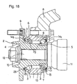
- Fig. 18 is a schematic diagram showing the structure of one example of the rolling bearing unit with seal ring having this kind of the seal ring for rotatably supporting the driven wheels of a vehicle on a suspension device.
- the above rolling bearing unit with seal ring is composed of an outer race 1, a hub 2, and a plurality of rolling members 3, 3.
- the hub 2 of these elements is composed of a hub body 4 and an inner race element 5 in combination.
- the above outer race 1 is fixed to a knuckle 8 constituting the suspension device while the wheels are securely connected to an attachment flange 9 of the above hub body 4.
- a spline shaft 12 provided on a constant velocity joint 11 is engaged with a spline hole 10 opened through the central location of this hub body 4.
- the internal space 13 accommodating the above respective rolling members 3, 3 is filled with a grease to lubricate the rolling contact portion between the rolling contact surfaces of the respective rolling members 3, 3 and the above respective outer raceways 6 and 6 and the inner raceways 7 and 7.
- seal rings 14a and 14b are provided respectively between the inner peripheral surface of the above outer race 1 at each of the opposite ends and the outer peripheral surface of the inner end of the above inner race element 5 and the intermediate portion of the above hub body 4 to close the openings of the above internal space 13 at each of the opposite ends.
- Fig. 19 illustrates the configuration of the seal ring 14a which is one of the seal rings 14a and 14b serving to close the opening at the inner end of the above internal space 13 (the inner side in the axial direction means the side closer to the center in the width direction of a vehicle in which the unit is assembled, and conversely the outer side means the outer side in the width direction, which definitions are applicable throughout this specification).
- This seal ring 14a is called a combination seal ring and composed of a metal core 15, a slinger 16 and a sealing member 17.
- the metal core 15 among these elements is formed as an annular ring in whole having an L-shaped cross section, and composed of an outer cylindrical portion 18 which can be fitted and fixed into the inner peripheral surface of the end portion of an outer race 1 and an outer circular ring portion 19 which is inwardly bent in the radial direction from the axially outer edge of this outer cylindrical portion 18.
- the above slinger 16 is formed as an annular ring having an L-shaped cross section, and composed of a radially inner cylindrical portion 20 which can be fitted and fixed onto the outer peripheral surface of the end portion of said inner race element 5 and an inner circular ring portion 21 which is outwardly bent in the radial direction from the axially inner edge of this radially inner cylindrical portion 20.
- the above sealing member 17 is made of a resilient material, for example, an elastomer such as a rubber, and provided with three seal lips 22 to 24 whose base end portion is fixedly connected to the above metal core 15.
- the remaining two seal lips 23 and 24 have tip edges to be in slidable contact with the outer peripheral surface of the radially inner cylindrical portion 20 of the above slinger 16 around the entire circumference.
- the seal ring 14b closing the opening of the above internal space 13 at the outer end is composed of a metal core 25 and a sealing member 26 as shown in Fig. 20.
- This sealing member 26 is made of a resilient material, for example, an elastomer such as a rubber, and provided with three seal lips 27 to 29 whose base end portion is fixedly connected to the above metal core 25.
- the seal lip 27, which is called a side lip and provided in the most outer location to outwardly project in the axial direction, has the tip edge to be in slidable contact with the inner surface of the base end portion of said attachment flange 9 around the entire circumference.
- the remaining two seal lips 28 and 29 have tip edges to be in slidable contact respectively with the portion continuing between the inner surface of this base end portion of the attachment flange 9 and the outer peripheral surface of the intermediate portion of said hub body 4, or with this outer peripheral surface of the intermediate portion around the entire circumference, respectively.
- the seal lips 22 and 27, which are located in the most outer positions exposed to foreign object such as muddy water among the three seal lips 22 to 24 and the three seal lips 27 to 29 constituting the above seal rings 14a and 14b respectively, and the intermediate seal lip 28 of the seal ring 14b are designed to have an approximately constant thickness from each base end portion to the corresponding tip portion.
- the distance between the outer circular ring portion 19 of the above metal core 15 and the inner circular ring portion 21 of the above slinger 16 deviates from the design value.
- the interference (the amount of elastic deformation) of the above seal lip 22 increases resulting in a higher contact pressure at the slidably contacting region between the tip edge portion of this seal lip 22 and the outer surface of the above inner circular ring portion 21.
- the sliding resistance (seal torque) at this slidably contacting region increases, and therefore it becomes likely that the above seal lip 22 wears and becomes limp, and the durability of the above seal ring 14a is hardly maintained.
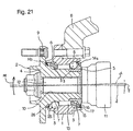
- the elastic deformation of the respective elements, occurring when the vehicle is moving makes inappropriate the sliding contact condition at the tip edge portions of the seal lips 22 and 27 with the corresponding counterpart surfaces. That is, the central axis of the above hub 2 may quickly be tilted relative to its neutral position due to the elastic deformation of the respective components of the rolling bearing unit on the basis of the moment exerted on the hub 2 through the attachment flange 9 from the land surface, with which the tires constituting wheels come in contact during the vehicle turns. In such a case, the sliding contact condition between the tip edge portions of the seal lips 22 and 27 and the corresponding counterpart surfaces becomes uneven, and therefore there is a problem that the sealing performance and the durability of the seal lips 22 and 27 are degraded and the like problem. This point will be explained with the seal ring 14a at the inner opening of the above internal space 13 as an example with reference to Figs. 21 to 22.
- the interferences of the above respective seal lips 22 and 27 are determined in order that, even when the central axis of the above hub 2 is tilted on the basis of the above moment load M to decrease the interferences of the above seal lips 22 and 27 in a location, the sealing performance is secured in the location. More specifically, the interferences of the respective seal lips 22 and 27 are determined to be somewhat larger with the above central axis being not tilted in order that, even if the above central axis is tilted, these respective seal lips 22 and 27 maintain at least minimum residual interferences required of the respective seal lips 22 and 27 to secure the sealing performance around the entire circumference.
- the present invention is made for the purpose of simultaneously meeting the contradictory requirements, i.e., decreasing the frictional resistance of a seal lip and improving the durability thereof, without compromising the sealing performance of this seal lip.
- the present invention is made for the purpose of realizing the structure in which the contact pressure at the slidably contacting region between the tip edge portion of a seal lip and the counterpart surface is less influenced by the variation of the interference due to the tilt of the central axis of a hub on the basis of assembling errors and a moment load while the tip edge portion of the seal lip can sufficiently follow the axial displacement variation of the slidably contacting region of a slinger caused in the axial direction by this tilt.
- the seal ring according to a first aspect is provided with a seal lip, in the same manner as the known seal ring as described above, which is made of a resilient material in the form of a circular ring in whole with a tip edge being in slidable contact with the adjacently located counterpart surface around the entire circumference.
- the above seal lip is formed with a most thin portion having a smallest thickness in the vicinity of the base end portion thereof. Then, a most thick portion having the largest thickness is provided adjacent to this most thin portion in the side of the tip edge, and shaped with the thickness being gradually decreased from this most thick portion to the tip edge portion.
- the thicknesses of the respective elements are controlled. That is, provided that the thickness of the most thick portion is t 1 , while a phantom line is defined which passes the center in the thickness direction of the seal lip, and provided that the thickness of this seal lip is t 2 at the center position of this phantom line from the most thick portion to the tip edge of the seal lip, and that the thickness of the tip edge is t 3 , then it is satisfied that 0.6 ⁇ t 2 /t 1 ⁇ 0.9 and 0.3 ⁇ t 3 /t 1 ⁇ 0.7, preferably 0.70 ⁇ t 2 /t 1 ⁇ 0.85 and 0.35 t 3 /t 1 ⁇ 0.65 as in Claim 3.
- the above seal lip may be provided with a notch, a projection or the like for several reasons, the above thicknesses t 1 , t 2 and t 3 in the case where such a notch or a projection is formed are defined on the assumption that such a notch, a projection or the like does not exist.
- the rolling bearing unit with seal ring is composed of an outer race with an outer raceway in the inner peripheral surface, an inner race with the inner raceway on the outer peripheral surface, a plurality of rolling members rollingly provided between the outer raceway and the inner raceway, and a seal ring closing the opening at the end portion of a space located between the inner peripheral surface of the above outer race and the outer peripheral surface of the above inner race in the same manner as the known seal ring as described above.
- the above seal ring is any of the seal rings as described above.
- the above rolling bearing unit with seal ring includes a so-called hub unit having one race of the outer race and the inner race rotatable at the time of use and functioning as a hub securely connected to a wheel at the time of use, and the other race of the outer race and the inner race which does not rotate at the time of use and functioning as a stationary race supported by a suspension device.
- seal ring of the present invention configured as described above, it is possible to simultaneously meet the contradictory requirements, i.e., decreasing the frictional resistance of the slidably contacting region between the seal lip and the counterpart surface and improving the durability of this seal lip, without compromising the sealing performance of this seal lip.
- the deformation of this seal lip is concentrated to the most thin portion located in the vicinity of the base end portion to minimize the influence of the variation of the interference of this seal lip upon the contact pressure at the slidably contacting region between the tip edge portion of this seal lip and the counterpart surface. Accordingly, the variation of the contact pressure at the above slidably contacting region is narrowed irrespective of the tilt of the central axis of the hub during a turning motion or irrespective assembling errors, and therefore it is possible to secure a sufficient sealing performance and reduce the above frictional resistance without incurring an excessive contact pressure at the above slidably contacting region in its neutral position (the initial setting position).
- the thickness of the seal lip is gradually decreased from the above most thick portion, which is located adjacent to this most thin portion, to the tip edge portion, and therefore when the tip edge portion of the above seal lip is abutted to the counterpart surface, the seal lip is elastically deformed also in the portion other than the above most thin portion.
- the force 1 ⁇ largely varies when the distance between the seal lip and the counterpart surface varies, while the variation of the force 2 ⁇ is relatively small when the distance between the seal lip and the counterpart surface varies. Also, the generation of this forces 2 ⁇ is approximately uniform around the entire circumference.
- the thicker the above seal lip and the greater the expansion of this seal lip in diameter the larger the contact pressure applied to the slidably contacting region by the hoop force 2 ⁇ among these two types of force as 1 ⁇ and 2 ⁇ .
- the wall thickness of this base end portion inclusive of the curved portion (round portion) of the base end portion of this seal lip becomes larger to making it difficult to expand the diameter of this portion. Because of this, while an urging force is hardly generated by the above hoop force, the contact pressure at the above slidably contacting region is generated mainly on the basis of the above bending force 1 ⁇ .
- the most thin portion provided at the base end portion functions as a hinge to decrease the force to constrain on the most thick portion located in the leading edge side of this most thin portion in the radial direction and in the axial direction. Because of this, the above hoop force 2 ⁇ is easily generated. As a result, even if the central axis of the seal ring is tilted relative to the central axis of the member providing the counterpart surface with which the tip edge portion of the seal lip constituting this seal ring comes in slidable contact to make uneven the distance between the metal core constituting the above seal ring and the counterpart surface, the contact surface pressure between the tip edge portion of the above seal lip and the counterpart surface can be kept uniform.
- Figs. 1 and 2 show a first example of the embodiment of the present invention.
- the characteristics of this example resides in that the sealing performance and the durability of a seal lip 22a are improved by devising the profile of the seal lip 22a constituting a seal ring 14a which serves to close the opening at the inner end of the internal space 13 with a plurality of rolling members 3, 3 provided therein.
- the structures and the functionality of the other elements are similar to those of the prior art structure as described above, and therefore, while redundant explanation is not repeated or is simplified with like symbols applied to like members, the following description is focused on the characteristic structure of the present invention differing from the above prior art structure.
- the above seal lip 22a which is called a side lip, is provided with a most thin portion 30 at the base end portion thereof by setting down the opposite surfaces of this base end portion toward the center in the thickness direction. Also, a most thick portion 31 having the largest thickness is provided adjacent to this most thin portion 30 in the side of the distal end of the above seal lip 22a. Furthermore, the thickness of the above seal lip 22a is gradually decreased from this most thick portion 31 to the tip edge portion in a convergent form.
- the thickness t 2 of this seal lip 22a at the center position of this phantom line S from the above most thick portion 31 to the leading edge of the seal lip 22a is determined to be no smaller than 0.6 times and no larger than 0.9 times the thickness t 1 of the above most thick portion 31 (0.6 ⁇ t 2 /t 1 ⁇ 0.9), preferably no smaller than 0.70 times and no larger than 0.85 times the thickness t 1 (0.70 ⁇ t 2 /t 1 ⁇ 0.85).
- the thickness t 3 of the tip edge portion is determined to be no smaller than 0.3 times and no larger than 0.7 times the thickness t 1 of this most thick portion 31 (0.3 ⁇ t 3 /t 1 ⁇ 0.7), preferably no smaller than 0.35 times and no larger than 0.65 times the thickness t 1 (0.35 ⁇ t 3 /t 1 ⁇ 0.65).
- the slinger 16 is fitted and fixed onto the inner end of the inner race element 5 by interference fitting.
- the tip edge of the above seal lip 22a is arranged to come in slidable contact with the outer surface of the inner circular ring portion 21 of the above slinger 16 around the entire circumference with an interference.
- the tip edge of this seal lip 22a can effectively follow the outer surface of the above inner circul r ring portion 21.
- the deformation of the above seal lip 22a is concentrated in a degree to the most thin portion 30 located in the vicinity of the base end portion to minimize the influence of the variation of the interference of this seal lip 22a upon the contact pressure at the slidably contacting region between the tip edge portion of this seal lip 22a and the outer surface of the above inner circular ring portion 21. Also, even when the central axis of the above slinger 16 is tilted relative to the central axis of the above seal ring 14a, the portion of the above seal lip 22a from the most thick portion 31 to the tip edge portion can be smoothly moved through rocking motion corresponding to the tilt of the above slinger 16 by making use of the above most thin portion 30 as a hinge.
- the tip edge portion of the above seal lip 22a can smoothly follow the outer surface of the above inner circular ring portion 21. Even in this state, a sufficient contact pressure can be applied to the slidably contacting region between the tip edge portion of the above seal lip 22a and the outer surface of the above inner circular ring portion 21 by the hoop force generated by expansion of the diameter of the leading portion of this seal lip 22a extending from the most thick portion 30 to the leading edge.
- the variation of the contact pressure at the above slidably contacting region is narrowed irrespective of the tilt of the central axis of the hub 2 during a turning motion or of assembling errors, and therefore it is possible to secure a sufficient sealing performance and reduce the frictional resistance at the above slidably contacting region without incurring an excessive contact pressure at the above slidably contacting region in its neutral position (the initial setting position).
- the thickness of the seal lip 22a is gradually decreased from the above most thick portion 31, which is located adjacent to this most thin portion 30, to the tip edge portion, and therefore when the tip edge portion of the above seal lip 22a is abutted to the counterpart surface, the seal lip 22a is elastically deformed also in the portion other than the above most thin portion 30, i.e., the above leading portion. As a result, it is possible to improve the durability of the above seal lip 22a by preventing an excessive elastic deformation of this most thin portion 30 and the premature relaxation of this most thin portion 30.
- a most thin portion 30 is formed with a pair of hollow places set down in the opposite surfaces of the above seal lip 22a toward the center in the wall thickness direction in the case of the example as illustrated, a most thin portion can be formed by providing such a hollow place only in one of the opposite surfaces of the base end portion of the seal lip.
- the profile of this hollow place is not limited to the profile as illustrated. Any profile can be employed as long as the deformation is concentrated to the base end portion of this seal lip 22a within the range in which the durability of the above seal lip 22a can be secured.
- a ridge 32 is formed around the entire circumference on the intermediate portion of the inner surface of the attachment flange 9 formed on the outer peripheral surface of the hub body 4.
- the inner peripheral surface of this ridge 32 is a partial spherical concave surface having a curvature radius R with the center of displacement of the above hub body 4 during a turning motion being the center thereof, or a partial conical concave surface arranged partially touching such a spherical concave surface.
- the outer peripheral surface of said outer race 1a located at the outer end portion to face the inner peripheral surface of the above ridge 32 is a partial spherical convex surface which is concentric with this inner peripheral surface and has a curvature radius slightly smaller than the above curvature radius R, or a partial conical convex surface arranged partially touching such a spherical convex surface.
- This partial spherical convex surface or partial conical convex surface is located opposed to the above partial spherical concave surface or partial conical concave surface, and a labyrinth seal is provided in the facing location.
- the gap at this labyrinth seal does not vary and is constant or substantially constant even when the central axis of the above hub body 4 is tilted during a turning motion. Because of this, a sufficient labyrinth sealing performance can be always obtained by decreasing the above gap.
- Fig. 3 shows a second example of the embodiment of the present invention.
- the most thin portion 30a formed of the base end portion of a seal lip 22b, called a side lip, provided in the most radially outer side of the sealing member 17 constituting the seal ring 14a is warped as viewed in its cross section. Also, this most thin portion 30a is formed approximately in the axial direction of the above seal ring 14a.
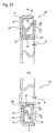
- Figs. 4 and 5 show a third and a fourth example of the embodiment of the present invention.
- seal lips 22d and 22e each called a side lip
- a most thin portion 30 at the base end portion thereof by setting down the opposite surfaces of this base end portion toward the center in the thickness direction.
- a most thick portion 31 having the largest thickness is provided adjacent to this most thin portion 30 in the side of the distal end of the above seal lips 22d and 22e.
- the thicknesses of the above seal lips 22d and 22e are gradually decreased from this most thick portion 31 to the tip edge portion in the same manner as the above first and second examples.
- the thickness dimensions of the tip portions of these seal lips 22d and 22e are prevented from being excessively small and can be secured even with abrasion. That is, in the case of the third example as illustrated in Fig. 4, the thickness dimension of the seal lip 22d is little diminished or rather becomes larger in the portion of the above seal lip 22d that is located in the radially inner side in its free state among the opposite side surfaces of the above seal lip 22d and is extending to the distal end beyond a point P displaced from the center toward the distal end in the surface opposite to the inner circular ring portion 21 constituting the slinger 16 in its use condition.
- the rate of diminishing the thickness dimension of the seal lip 22e becomes smaller toward the distal end from a point P similar as that of the above third example and from a point Q located in the opposite surface of the seal lip 22e approximately opposite the point P. Even if the thickness is increased near the tip edge portion, the thickness is gradually decreased to the above points P and Q and therefore the elastic deformation of the above respective seal lips 22d and 22e can be sufficiently secured. Meanwhile, the chained line plotted in the seal lips 22d and 22e shown in Figs. 4 to 5 shows the design of the cross section illustrated on the assumption that the thickness dimension is decreased, as it is, beyond the points P and Q toward the leading edge. It is for the following reason that the rate of diminishing the thickness dimension t 3 (refer to Fig. 2) of the tip edge portion of the seal lips 22d and 22e is decreased or that the thickness dimension is increased.
- the thicknesses of the above seal lips 22d and 22e are gradually thinned toward the point in the vicinity of the leading edges of the seal lips 22d and 22e, it is possible to attenuate the strain applied to the tip portions of the above seal lips 22d and 22e in the assembled condition. Furthermore, since this seal lips 22d and 22e are provided with the most thin portion 30 as diminished at the base end portion, it is possible to improve the following performance of the tip edge portion of the above seal lips 22d and 22e responsive to the movement of the side surface of the above inner circular ring portion 21 to maintain approximately constant the above pressing force in the long term use.
- Fig. 6 shows a fifth example of the embodiment of the present invention.
- This example shows the seal ring 14b, to which the present invention is applied, for closing the outer end portion of the internal space 13 (refer to Fig. 1) of the rolling bearing unit.
- most thin portions 30b and 30c are formed respectively on the base end portion of the seal lip 27a, which is located in the most outer location among the three seal lips 27a, 28a and 29 constituting this seal ring 14b to outwardly project in the axial direction, and the base end portion of the seal lip 28a, which is located in an intermediate location thereamong.
- Fig. 7 shows a sixth example of the embodiment of the present invention.
- the tip edge portion of the seal lip 35 laterally extending (toward the right in Fig. 7) from a seal ring 33 of one (the left one in Fig. 7) of a pair of the seal rings 33 and 34 adjacent to each other in the axial direction is arranged to come in slidable contact with the side surface of the metal core 36 constituting the other seal ring 34 (the right one in Fig. 7) around the entire circumference.
- the seal ring 33 as one of the above pair of seal rings 33 and 34, is locked to the inner peripheral surface of the outer race at its outer peripheral edge portion and comes in slidable contact with the outer peripheral surface of the inner race at its inner peripheral edge portion around the entire circumference.
- the other seal ring 34 is locked to the outer peripheral surface of the inner race at its inner peripheral edge portion and comes in slidable contact with the inner peripheral surface of the outer race at its peripheral edge around the entire circumference.
- the above seal lip 35 is formed with the most thin portion 30d at its base end portion thereof and the most thick portion 31c in an adjacent location.
- the tip edge portion of the above seal lip 35 is thereby arranged to suitably come in slidable contact with the side surface of the above metal core 36 even when the central axis of the above outer race and the central axis of the above inner race are misaligned with each other due to a moment load and the like. Also, the contact surface pressure between the tip edge portion of the above seal lip 35 and the side surface of the above metal core 36 little varies by the variation of the interference due to the assembling errors of the inner and outer races and the like.
- Fig. 8 shows a seventh example of the embodiment of the present invention.
- the sealing member 37 constituting the seal ring 33a in one side is formed with a convex portion 38 in an location outside of the seal lip 35 in the radial direction around the entire circumference.
- a labyrinth seal is therefore formed in that location by locating the tip surface of this convex portion 38 close and opposed to the side surface of the metal core 36 constituting the other seal ring 34.
- the tip surface of the above convex portion 38 and the side surface of the metal core 36 located to be close and opposed to each other are designed respectively as a partial spherical surface having, as the center, the center of displacement caused by a moment load or a partial conical surface arranged partially touching such a spherical surface in order that the gap at the above labyrinth seal does not vary irrespective of the displacement.
- this labyrinth seal it is possible to maintain low the surface pressure in the slidably contacting region between the tip edge portion of the seal lip 35 and the side surface of the metal core 36, while securing a necessary sealing performance, and therefore lower the torque applied to the rolling bearing unit with seal ring.
- Fig. 9 shows an eighth example of the embodiment of the present invention.
- the present invention is applied to a combination seal ring comprising seal rings each of which is composed of a metal core and a sealing member.
- a seal lip 39 laterally extending to come in slidable contact with the side surface of the metal core constituting the counterpart seal ring is provided with a most thin portion 30e and a most thick portion 31d located adjacent to each other as viewed from the base end side.
- Fig. 10 shows a ninth example of the embodiment of the present invention.
- a pair of seal rings are located to have sealing members partially opposed to each other in order to form a labyrinth seal in that location.
- the opposite surfaces of the pair of sealing members which are located to be close and opposed to each other, are designed respectively as a partial spherical surface having, as the center, the center of displacement caused by a moment load or a partial conical surface arranged partially touching such a spherical surface in order that the gap at the above labyrinth seal does not vary irrespective of the displacement.
- the structures of the other elements are similar to those of the eighth example as described above.
- the most thin portion can be formed by providing a pair of hollow places set down in the opposite surfaces of the seal lip toward the center in the wall thickness direction, or by providing such a hollow place only in any one of the opposite surfaces of the base end portion of the seal lip.
- An appropriate profile other than that as illustrated in the figure can be employed as the profile of the hollow place in the same manner as the above first example.
- the direction of the seal lip (for example, the seal lip 24 shown in Fig. 2) closest to the internal space 13 (refer to Fig. 1) is arbitrary. However, as illustrated in Fig.
- the type of the rubber material used to form the sealing member is arbitrary.
- a conductive rubber material can be used for inhibiting radio noise by lessening the discharge from a rolling bearing unit with seal ring.
- the basic structure of the rolling bearing unit with seal ring is not limited to the application to the structure for rotating an inner race as illustrated in Fig. 1, it is applicable also to the structure for rotating an outer race.
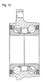
- the present invention is not limited to the so called third generation hub unit as illustrated in Fig. 1 in which the inner raceway 7 is formed directly on the hub body 4, but applicable also to the so called first generation hub unit, and the second generation hub unit as illustrated in Fig. 12 to Fig. 14.
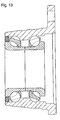
- the present invention is not limited to the structure implemented with balls as rolling members, but applicable also to the hub unit implemented with taper rollers as rolling members as illustrated in Fig. 15. Needless to say, the present invention is applicable also to the first or third generation hub unit in which the rolling members are changed from balls to taper rollers.
- the present invention is applicable also to rolling bearing units with seal ring other than for use in a vehicle to obtain the effects and advantages as described above, as long as the sealing performance is affected by the variation of the interference of the seal lip due to the influence of the moment load applied during a turning motion or because of assembling errors.
- Fig. 16 shows a combination seal ring used in this simulation with a metal core 15 and a slinger 16 being sufficiently apart from each other to have a sealing member 17 in its free state.
- a phantom line segment "S" is defined which passes the center in the thickness direction throughout the entire length of the cross section of a seal lip 22c formed on this sealing member 17. Meanwhile, the form of this phantom line S is determined in accordance with the profile of this seal lip 22c and may be a straight line, a kinked line, a curved line or any other line.
- a point A is the point corresponding to the most thick portion 31e
- a point B the point corresponding to the tip edge portion of the above seal lip 22c
- a point C the point corresponding to the midpoint between the point A and the point B.
- the wall thickness of the above seal lip 22c is t 1 at the point A, t 2 at the point C and t 3 at the point B.
- Fig. 17 shows the result thereof.
- This Fig. 17 shows the ratio in wall thicknesses between the above point A and the above point B (t 2 /t 1 ) in the ordinate and the ratio in wall thicknesses between the above point A and the above point C (t 3 /t 1 ) in the abscissa respectively.
- Fig. 17 illustrating the ratios of the maximum strain obtained in these conditions, if it is satisfied with the relations between the wall thickness t 1 , t 2 and t 3 of these points that 0.6 ⁇ t 2 /t 1 ⁇ 0.9 and 0.3 ⁇ t 3 /t 1 ⁇ 0.7, preferably 0.70 ⁇ t 2 /t 1 ⁇ 0.85 and 0.35 ⁇ t 3 /t 1 ⁇ 0.65, it is understood that the durability of the seal ring inclusive of this seal lip 22c can be improved by maintaining low the maximum strain generated in the above seal lip 22c and preventing the relaxation and damage such as cracks of this seal lip 22c.
- the above optimal range in accordance with the result of this simulation is applicable to all the seal rings as targets of the present invention inclusive of the respective examples of the embodiments as described above.
- seal ring and the rolling bearing unit with seal ring in accordance with the present invention are constructed and operated as mentioned above, it is possible to optimize the surface pressure at the slidably contacting region between the tip edge portion of the seal lip that is located closest to the outer space and the mating surface, the seal lip being most important for preventing the entrance of foreign objects irrespective of the displacement of the respective elements during operation or because of assembling errors. Also, the seal lip can follow the displacement of the counterpart surface. It is therefore possible to reduce the friction of the above seal lip and improve the durability of this seal lip.
Landscapes
- Engineering & Computer Science (AREA)
- General Engineering & Computer Science (AREA)
- Mechanical Engineering (AREA)
- Sealing Of Bearings (AREA)
- Sealing With Elastic Sealing Lips (AREA)
- Rolling Contact Bearings (AREA)
Abstract
Description
Claims (5)
- A seal ring having a seal lip made of a resilient member and formed generally in an annular shape, and having a tip edge in sliding contact with an adjacent mating surface generally around the circumference, wherein, the seal lip is formed with a most thin portion having a smallest thickness in the vicinity of the base end portion thereof, wherein, a most thick portion having the largest thickness is provided adjacent to this most thin portion in the side of the tip edge, and wherein the thickness is gradually decreased from this most thick portion to the tip edge.
- A seal ring of Claim 1, wherein, provided that the thickness of the most thick portion is t1, while a phantom line is defined which passes the center in the thickness direction of the seal lip, that the thickness of this seal lip is t2 at the center position of this phantom line from the most thick portion to the tip edge of the seal lip, and that the thickness of the tip edge is t3, then it is satisfied that 0.6≦t2/t1≦0.9 and 0.3≦t3/t1≦0.7.
- A seal ring of Claim 2, wherein 0.70≦t2/t1≦0.85 and 0.35≦ t3/t1≦0.65.
- A rolling bearing unit with seal ring comprised of an outer race with an outer raceway in the inner peripheral surface thereof, an inner race with the inner raceway on the outer peripheral surface thereof, a plurality of rolling members rollingly provided between the outer raceway and the inner raceway, and a seal ring closing the opening at the end portion of a space located between the inner peripheral surface of the outer race and the outer peripheral surface of the inner race, the seal ring being any one of Claims 1 to 3.
- A rolling bearing unit with seal ring of Claim 4, wherein one race of the outer race and the inner race rotatable at the time of use is a hub securely connected to a wheel at the time of use, while the other race of the outer race and the inner race which does not rotate at the time of use is a stationary race supported by a suspension device.
Applications Claiming Priority (5)
| Application Number | Priority Date | Filing Date | Title |
|---|---|---|---|
| JP2002083135 | 2002-03-25 | ||
| JP2002083135 | 2002-03-25 | ||
| JP2002353397 | 2002-12-05 | ||
| JP2002353397 | 2002-12-05 | ||
| PCT/JP2003/003527 WO2003081096A1 (en) | 2002-03-25 | 2003-03-24 | Seal ring, and roller bearing unit with seal ring |
Publications (2)
| Publication Number | Publication Date |
|---|---|
| EP1496293A1 true EP1496293A1 (en) | 2005-01-12 |
| EP1496293A4 EP1496293A4 (en) | 2007-12-12 |
Family
ID=28456236
Family Applications (1)
| Application Number | Title | Priority Date | Filing Date |
|---|---|---|---|
| EP03712853A Ceased EP1496293A4 (en) | 2002-03-25 | 2003-03-24 | Seal ring, and roller bearing unit with seal ring |
Country Status (5)
| Country | Link |
|---|---|
| US (1) | US7021830B2 (en) |
| EP (1) | EP1496293A4 (en) |
| JP (1) | JPWO2003081096A1 (en) |
| AU (1) | AU2003221012A1 (en) |
| WO (1) | WO2003081096A1 (en) |
Cited By (2)
| Publication number | Priority date | Publication date | Assignee | Title |
|---|---|---|---|---|
| CN102089161A (en) * | 2008-07-08 | 2011-06-08 | 株式会社捷太格特 | axle bearing system |
| EP2787233A4 (en) * | 2011-11-29 | 2015-12-09 | Nsk Ltd | ROLLER BEARING UNIT WITH COMBINED SEAL RING |
Families Citing this family (28)
| Publication number | Priority date | Publication date | Assignee | Title |
|---|---|---|---|---|
| DE102006047014B4 (en) * | 2005-10-04 | 2023-01-19 | Ntn Corp. | wheel bearing device |
| US20070116389A1 (en) * | 2005-11-10 | 2007-05-24 | Chia-Wei Lin | Roller bearing device for bicycles |
| JP2007239987A (en) * | 2006-02-10 | 2007-09-20 | Nsk Ltd | Seal device and rolling bearing unit with seal device |
| DE102007042368A1 (en) * | 2007-09-06 | 2009-03-19 | Schaeffler Kg | Sealing arrangement for a bearing |
| US20090107731A1 (en) * | 2007-10-30 | 2009-04-30 | George Fedorovich | Drillbit seal |
| JP2009115110A (en) * | 2007-11-01 | 2009-05-28 | Nok Corp | Sealing device |
| JP5303909B2 (en) * | 2007-11-20 | 2013-10-02 | 株式会社ジェイテクト | Sealing device, rolling bearing and wheel rolling bearing |
| JP5180561B2 (en) * | 2007-11-20 | 2013-04-10 | 株式会社ジェイテクト | Sealing device, rolling bearing and wheel rolling bearing |
| CN102046994B (en) * | 2008-05-27 | 2013-11-20 | 株式会社捷太格特 | Sealing device for rolling bearing |
| WO2010136058A1 (en) * | 2009-05-25 | 2010-12-02 | Aktiebolaget Skf | A bearing seal assembly, particularly for use in agricultural applications |
| US8061903B2 (en) * | 2010-01-28 | 2011-11-22 | Rexnord Industries, Llc | Bearing assembly with extended maintenance interval |
| US8740464B2 (en) | 2011-11-02 | 2014-06-03 | Rexnord Industries, Llc | Bearing assembly having a floating seal |
| US8845201B2 (en) * | 2012-08-06 | 2014-09-30 | GM Global Technology Operations LLC | Bearing with sealing slinger |
| ITTO20130980A1 (en) * | 2013-11-29 | 2015-05-30 | Skf Ab | LOW FRICTION SEALING COMPLEX, COUPLING SYSTEM WITH A BEARING RING AND WHEEL HUB UNIT EQUIPPED WITH SUCH SEALING COMPLEX |
| JP2017057891A (en) * | 2015-09-15 | 2017-03-23 | ニッタ株式会社 | Seal material and seal mechanism |
| EP3351833B1 (en) * | 2015-09-25 | 2020-07-08 | NOK Corporation | Sealing device for differential mechanism |
| DE102015012998B4 (en) | 2015-10-07 | 2017-05-04 | Audi Ag | Sealing system for a rolling bearing |
| JP7182948B2 (en) * | 2017-11-21 | 2022-12-05 | 光洋シーリングテクノ株式会社 | sealing device |
| EP3501960B1 (en) * | 2017-12-22 | 2021-11-10 | Campagnolo S.r.l. | Bicycle bottom bracket |
| EP3779246B1 (en) * | 2018-04-06 | 2025-05-14 | NOK Corporation | Seal device |
| JP2020079619A (en) * | 2018-11-13 | 2020-05-28 | 中西金属工業株式会社 | Seal for rotation |
| KR102621711B1 (en) | 2018-11-20 | 2024-01-08 | 현대자동차주식회사 | Seal assembly for wheel bearing |
| IT201900020112A1 (en) * | 2019-10-31 | 2021-05-01 | Skf Ab | DYNAMIC INTERFERENCE SEALING DEVICE AND SYSTEM WITH IMPROVED CONTACT BEHAVIOR |
| US12072025B2 (en) * | 2021-04-05 | 2024-08-27 | Aktiebolaget Skf | Axial seal assembly with hinged lip |
| US20230016354A1 (en) * | 2021-07-13 | 2023-01-19 | Aktiebolaget Skf | Low friction seal assembly for truck hubs |
| US12000434B2 (en) * | 2021-07-13 | 2024-06-04 | Aktiebolaget Skf | Seal assembly for truck hubs with radial labyrinth |
| US11746828B2 (en) | 2021-11-25 | 2023-09-05 | Aktiebolaget Skf | Transport securable axial seal assembly |
| US11796003B2 (en) | 2021-11-25 | 2023-10-24 | Aktiebolaget Skf | Flinger for a seal assembly of a wheel bearing assembly |
Family Cites Families (23)
| Publication number | Priority date | Publication date | Assignee | Title |
|---|---|---|---|---|
| US3822890A (en) * | 1973-01-15 | 1974-07-09 | Roulements Soc Nouvelle | Bearing seals |
| IT1156424B (en) * | 1978-01-23 | 1987-02-04 | Fiat Spa | SEALING AND PROTECTION DEVICE OF THE BEARING ON THE MOTOR WHEEL ROD |
| JPS61182461A (en) | 1985-02-06 | 1986-08-15 | Nippon Denso Co Ltd | Inertia plunging type starter |
| JPH0135982Y2 (en) * | 1985-05-08 | 1989-11-01 | ||
| JPS6316929A (en) | 1986-07-07 | 1988-01-23 | Matsushita Electric Ind Co Ltd | Inspection adjustment head |
| SE454909B (en) * | 1986-11-12 | 1988-06-06 | Skf Ab | Centrifugal force regulated sealing device |
| JPH01115070A (en) | 1987-10-28 | 1989-05-08 | Hitachi Ltd | Assembling and connecting construction of wiring board |
| JPH0535247Y2 (en) * | 1987-12-24 | 1993-09-07 | ||
| JPH01115070U (en) * | 1988-01-29 | 1989-08-02 | ||
| JPH02113173A (en) * | 1988-10-20 | 1990-04-25 | Nok Corp | Sealing device |
| JP2507600B2 (en) | 1989-06-02 | 1996-06-12 | 日本電気株式会社 | Temporary update control method for drawing information |
| JPH0410164A (en) | 1990-04-27 | 1992-01-14 | Sharp Corp | Character processing device |
| JPH0810713Y2 (en) * | 1990-05-18 | 1996-03-29 | エヌオーケー株式会社 | Sealing device |
| JPH0462966A (en) | 1990-07-02 | 1992-02-27 | Fujitsu Ltd | Mosfet masked rom |
| JPH0573364A (en) | 1991-09-11 | 1993-03-26 | Fujitsu Ltd | Most priority alarm output circuit |
| JPH0573365A (en) | 1991-09-17 | 1993-03-26 | Nec Software Ltd | Bug analysis support system |
| FR2700588B1 (en) * | 1993-01-19 | 1995-02-17 | Roulements Soc Nouvelle | Mounting device with integrated encoder seal. |
| JPH09287619A (en) * | 1996-02-23 | 1997-11-04 | Nippon Seiko Kk | Rolling bearing unit with sealing device |
| JPH10252762A (en) | 1997-03-12 | 1998-09-22 | Nippon Seiko Kk | Sealing device for rolling bearings |
| JPH11304827A (en) * | 1998-04-22 | 1999-11-05 | Nippon Seiko Kk | Rolling bearing unit with encoder |
| JP2000289405A (en) * | 1999-04-02 | 2000-10-17 | Nsk Ltd | Combination seal ring with encoder |
| GB9914442D0 (en) * | 1999-06-22 | 1999-08-18 | Kvaerner Metals Davy Ltd | Sealing assembly |
| IT1320399B1 (en) * | 2000-06-06 | 2003-11-26 | Skf Ind Spa | SEALING DEVICE FOR FLANGED BEARING. |
-
2003
- 2003-03-24 JP JP2003578792A patent/JPWO2003081096A1/en active Pending
- 2003-03-24 EP EP03712853A patent/EP1496293A4/en not_active Ceased
- 2003-03-24 AU AU2003221012A patent/AU2003221012A1/en not_active Abandoned
- 2003-03-24 WO PCT/JP2003/003527 patent/WO2003081096A1/en not_active Ceased
-
2004
- 2004-09-24 US US10/955,337 patent/US7021830B2/en not_active Expired - Lifetime
Cited By (8)
| Publication number | Priority date | Publication date | Assignee | Title |
|---|---|---|---|---|
| CN102089161A (en) * | 2008-07-08 | 2011-06-08 | 株式会社捷太格特 | axle bearing system |
| EP2301766A4 (en) * | 2008-07-08 | 2012-04-18 | Jtekt Corp | Bearing device for axle |
| US8770848B2 (en) | 2008-07-08 | 2014-07-08 | Jtekt Corporation | Axle bearing system |
| CN102089161B (en) * | 2008-07-08 | 2014-08-13 | 株式会社捷太格特 | axle bearing system |
| CN103978837A (en) * | 2008-07-08 | 2014-08-13 | 株式会社捷太格特 | Axle bearing system |
| CN103978837B (en) * | 2008-07-08 | 2016-06-29 | 株式会社捷太格特 | Bearing device for axle |
| EP2787233A4 (en) * | 2011-11-29 | 2015-12-09 | Nsk Ltd | ROLLER BEARING UNIT WITH COMBINED SEAL RING |
| US9534636B2 (en) | 2011-11-29 | 2017-01-03 | Nsk Ltd. | Rolling bearing unit with combination seal ring |
Also Published As
| Publication number | Publication date |
|---|---|
| JPWO2003081096A1 (en) | 2005-07-28 |
| WO2003081096A1 (en) | 2003-10-02 |
| EP1496293A4 (en) | 2007-12-12 |
| US7021830B2 (en) | 2006-04-04 |
| US20050089254A1 (en) | 2005-04-28 |
| AU2003221012A1 (en) | 2003-10-08 |
Similar Documents
| Publication | Publication Date | Title |
|---|---|---|
| US7021830B2 (en) | Seal ring and rolling bearing unit with seal ring | |
| US6206380B1 (en) | Seal device for rolling bearing | |
| US7731200B2 (en) | Seal assembly, and rolling bearing and hub unit assembled therewith | |
| US10479139B2 (en) | Wheel bearing apparatus | |
| CN1061135C (en) | Sealing structure for a bearing | |
| CN109416079B (en) | Sealing means | |
| US20070201782A1 (en) | Seal device and rolling bearing unit with seal device | |
| US7674044B2 (en) | Sealing device | |
| EP2693068A1 (en) | Bearing device for wheel | |
| US20100066030A1 (en) | Hermetic sealing device | |
| JP6111740B2 (en) | Rolling bearing unit for wheel support | |
| CN203297366U (en) | Rolling bearing component for supporting vehicle wheel | |
| CN211778585U (en) | Hub unit bearing | |
| JP2005291450A (en) | Seal ring and rolling bearing unit with seal ring | |
| US8678660B2 (en) | Sealing device, rolling bearing and rolling bearing for wheel | |
| JP7119992B2 (en) | hub unit bearing | |
| JP4200705B2 (en) | Rolling bearing unit with seal ring | |
| US20210010532A1 (en) | Bearing device for wheels | |
| JP2004169849A (en) | Seal ring and rolling bearing unit with seal ring | |
| JP2023144566A (en) | Bearing device for wheels | |
| JP2021173368A (en) | Rolling bearing equipment | |
| JPH07317780A (en) | Sealed thrust bearing | |
| KR20250061811A (en) | Bearing device for wheel | |
| JP6967831B2 (en) | Bearing device for wheels | |
| JP2005048895A (en) | Seal ring and rolling bearing unit with seal ring |
Legal Events
| Date | Code | Title | Description |
|---|---|---|---|
| PUAI | Public reference made under article 153(3) epc to a published international application that has entered the european phase |
Free format text: ORIGINAL CODE: 0009012 |
|
| 17P | Request for examination filed |
Effective date: 20041025 |
|
| AK | Designated contracting states |
Kind code of ref document: A1 Designated state(s): DE FR GB |
|
| AX | Request for extension of the european patent |
Extension state: AL LT LV MK |
|
| A4 | Supplementary search report drawn up and despatched |
Effective date: 20071112 |
|
| 17Q | First examination report despatched |
Effective date: 20120808 |
|
| REG | Reference to a national code |
Ref country code: DE Ref legal event code: R003 |
|
| STAA | Information on the status of an ep patent application or granted ep patent |
Free format text: STATUS: THE APPLICATION HAS BEEN REFUSED |
|
| 18R | Application refused |
Effective date: 20160125 |