EP1496268A1 - Pyrotechnischer Stellantrieb mit variabler Schubkraft - Google Patents
Pyrotechnischer Stellantrieb mit variabler Schubkraft Download PDFInfo
- Publication number
- EP1496268A1 EP1496268A1 EP04291466A EP04291466A EP1496268A1 EP 1496268 A1 EP1496268 A1 EP 1496268A1 EP 04291466 A EP04291466 A EP 04291466A EP 04291466 A EP04291466 A EP 04291466A EP 1496268 A1 EP1496268 A1 EP 1496268A1
- Authority
- EP
- European Patent Office
- Prior art keywords
- actuator
- chamber
- combustion chamber
- piston
- sliding
- Prior art date
- Legal status (The legal status is an assumption and is not a legal conclusion. Google has not performed a legal analysis and makes no representation as to the accuracy of the status listed.)
- Granted
Links
Images


Classifications
-
- F—MECHANICAL ENGINEERING; LIGHTING; HEATING; WEAPONS; BLASTING
- F15—FLUID-PRESSURE ACTUATORS; HYDRAULICS OR PNEUMATICS IN GENERAL
- F15B—SYSTEMS ACTING BY MEANS OF FLUIDS IN GENERAL; FLUID-PRESSURE ACTUATORS, e.g. SERVOMOTORS; DETAILS OF FLUID-PRESSURE SYSTEMS, NOT OTHERWISE PROVIDED FOR
- F15B15/00—Fluid-actuated devices for displacing a member from one position to another; Gearing associated therewith
- F15B15/20—Other details, e.g. assembly with regulating devices
- F15B15/24—Other details, e.g. assembly with regulating devices for restricting the stroke
-
- B—PERFORMING OPERATIONS; TRANSPORTING
- B60—VEHICLES IN GENERAL
- B60R—VEHICLES, VEHICLE FITTINGS, OR VEHICLE PARTS, NOT OTHERWISE PROVIDED FOR
- B60R21/00—Arrangements or fittings on vehicles for protecting or preventing injuries to occupants or pedestrians in case of accidents or other traffic risks
- B60R21/34—Protecting non-occupants of a vehicle, e.g. pedestrians
-
- B—PERFORMING OPERATIONS; TRANSPORTING
- B60—VEHICLES IN GENERAL
- B60R—VEHICLES, VEHICLE FITTINGS, OR VEHICLE PARTS, NOT OTHERWISE PROVIDED FOR
- B60R22/00—Safety belts or body harnesses in vehicles
- B60R22/18—Anchoring devices
- B60R22/195—Anchoring devices with means to tension the belt in an emergency, e.g. means of the through-anchor or splitted reel type
- B60R22/1954—Anchoring devices with means to tension the belt in an emergency, e.g. means of the through-anchor or splitted reel type characterised by fluid actuators, e.g. pyrotechnic gas generators
- B60R22/1955—Linear actuators
-
- F—MECHANICAL ENGINEERING; LIGHTING; HEATING; WEAPONS; BLASTING
- F15—FLUID-PRESSURE ACTUATORS; HYDRAULICS OR PNEUMATICS IN GENERAL
- F15B—SYSTEMS ACTING BY MEANS OF FLUIDS IN GENERAL; FLUID-PRESSURE ACTUATORS, e.g. SERVOMOTORS; DETAILS OF FLUID-PRESSURE SYSTEMS, NOT OTHERWISE PROVIDED FOR
- F15B15/00—Fluid-actuated devices for displacing a member from one position to another; Gearing associated therewith
- F15B15/19—Pyrotechnical actuators
Definitions
- the technical field of the invention is that of pyrotechnic actuators comprising a piston and having for essential function to exert a push for move an object by making the piston emerge.
- the pyrotechnic actuators according to the invention are particularly suitable for use in security systems implemented in vehicles for example, to cushion the moving certain parts that were put in movement during a mechanical shock of the vehicle automobile with an external element, such as a seat belt, the front bumper of the vehicle, the steering column or the hood of the vehicle in the case of a frontal collision between the vehicle and a pedestrian.
- This cylinder comprises a gas generator pyrotechnic, a piston, a combustion chamber of pyrotechnic materials and a backpressure chamber as well as an intermediate chamber said combustion chamber and an end of the piston.
- a channel connects the intermediate chamber to the chamber of against pressure. The gases emitted by the generator put under pressure the intermediate chamber to oppose the movement of the piston and thus dampen its stroke, a part of said gases being conveyed by the channel to the counterpressure chamber.
- the patent application FR 2 824 875 relates to a pyrotechnic actuator having a body, a piston, and a retaining washer of said piston in said body.
- the actuator can either exert a push on an object by causing said piston to emerge from said body, to release a mechanical part by retracting the piston in said body.
- the pyrotechnic actuators described in these two patents have a nominal operation characterized by a constant amplitude displacement of the piston, creating a unique effect on parts or objects intended to interact with said actuators.
- the pyrotechnic actuators according to the invention intervene a mechanical device of regulation of pressure in the piston sliding chamber to control the amplitude of movement of said piston. In this way, the pyrotechnic actuators according to the invention have a variable thrust effect or even with configurable travel and can therefore adapt to a plurality of configurations requiring a more or less displacement of the piston.
- the subject of the present invention relates to a pyrotechnic actuator comprising a gas generator pyrotechnic, a combustion chamber and a piston able to move in a sliding chamber under the effect of said gases, characterized in that said actuator comprises a shutter device set after triggering said actuator for, on the one hand, close the sliding chamber and, on the other hand, ensure the depressurization of the room of combustion.
- the amplitude of displacement of the piston in the sliding chamber is related to the level of pressure reached in said chamber.
- the shutter this chamber freezes the piston in a position determined. Once this closure is assured, the gases accumulate in the combustion chamber, inconsiderate way, with a risk of bursting negligible. It is therefore necessary to ensure most of the combustion chamber depressurization quickly possible after shutting the chamber of sliding.
- the shutter device is autonomous and can be triggered from a central control.
- Decoupling the triggering of the device shutter with that of actuator tripping contributes to increase the flexibility of use of the said actuator by allowing a free intervention of the user at the moment he deems most appropriate.
- the shutter device is included in the combustion chamber and is at contact of the sliding chamber.
- the device shutter consists of a drawer capable of move under the effect of an engine in an enclosure of sliding.
- the engine is a pyrotechnic gas generator.
- the pyrotechnic gas generator is provided an ignition system and a pyrotechnic charge gas generator.
- the displacement of the piece drawer is made along an axis perpendicular to that of the displacement of the piston.
- the sliding chamber is provided with a vent, the sliding chamber and the combustion chamber being isolated from each other by a veil of material.
- the sliding chamber and the combustion chamber do not communicate with each other, and said enclosure constitutes an open space on outside through the vent.
- the drawer is hollow and has one end cutting, so that the displacement of said piece in the sliding chamber first leads to the rupture of the veil of matter, then, simultaneously, shutting the sliding chamber of the piston and the communication of the combustion chamber with the sliding chamber. More precisely, the cutting end of the drawer part comes into contact the veil of matter then pierces it, while the hollow part of the drawer piece becomes a conduit which ensures the passage between the combustion chamber and the sliding chamber.
- the shutter of the room sliding is achieved by means of a part of the side wall of the drawer part.
- the combustion chamber has at least one vent opening on the outside of said actuator so that the shutter device, which initially closes said vent and allows communication between the chamber sliding and combustion chamber, moves to come close the sliding chamber and release the vent to evacuate the gases from the chamber of combustion.
- the drawer is crossed by a channel initially connecting the combustion chamber to the sliding chamber, said part being suitable for move in the sliding space under the effect of motor, so that the channel connects the chamber of combustion outside the actuator at the level of the wind.
- the combustion chamber has a zone of weakness, so the shutter device that initially allows communication between the sliding chamber and the combustion chamber moves to close the sliding chamber and cause the opening of the combustion chamber at its zone of embrittlement.
- the drawer is hollow and presents a cutting end, so that the displacement of said piece in the sliding chamber causes the shutter of the sliding chamber and causes, by mechanical impact, the rupture of the embrittlement to evacuate gases from the generator to the outside of said actuator.
- the hollow part serves as a conduit for route the gases from the combustion chamber to the outside of the actuator.
- the combustion chamber has a calibrated cap suitable for break beyond a threshold pressure to evacuate gas out of the actuator.
- the piston has a body extended by a rod, the diameter of said body being significantly lower than that of the chamber of sliding.
- the actuator comprises a non-return device preventing the return movement of the piston towards inside the sliding chamber.
- the sliding chamber is located between the shutter device and the piston body.
- the actuator can comprise means of resistance to the movement of the piston created under the effect of gases.
- these means of resistance consist of a spring arranged around of the piston rod.
- Pyrotechnic actuators have the advantage of being autonomous and having a reduced size thanks to a great simplicity of design. They can therefore be easily inserted in any type of device or object requiring the functions required by such actuators. They present, in addition all the advantages related to the use of pyrotechnic charges, know: reliability due to the control of the ignition, reduced footprint due to the small size of the loads pyrotechnics, and high variability of effects due to the diversity of pyrotechnic compositions be retained for these actuators. Finally, the use pyrotechnic charges allows a sequential ignition perfectly controlled between the actuator and the shutter device.
- the pyrotechnic actuator (1, 1a, 1b, 1c) according to the invention is intended to exert a pushing effect against an outside room.
- the resistance exerted by this outer part is materialized in the figures 1A to 4 by a spring R fixed on a plate and placed in opposition to the movement of the piston 9 of the actuator (1, 1a, 1b, 1c according to the invention, described below
- an actuator pyrotechnic device (1, 1a, 1b, 1c) is consisting of a hollow body 2 defining three parts in continuity with one another: combustion chamber 3 extended by a device shutter 4, itself extended by a chamber of sliding 5.
- the combustion chamber 3 which is cylindrical, has at one of its extremities a electropyrotechnic ignition system 6 and houses a pyrotechnic gas generator 7.
- the other end of said chamber 3 has an opening opening through through a passage 8 on the chamber of sliding 5 which also has a cylindrical shape and in which is housed a piston 9 having a body cylindrical 10 extended by a central rod 11 more small diameter.
- the body 10 of the piston 9 has a diameter significantly smaller than the diameter of the wall internal of the sliding chamber 5, so that said piston 9 can slide in a sealed manner in said chamber 5. Seals may be provided on the piston 9 to obtain a seal perfect.
- the sliding chamber 5 has one from its ends an opening, from which emerges the free end of the central rod 11 of the piston 9, said free end being covered by a plug 12 having a flat circular face 13.
- the axis of combustion chamber revolution 3 is confused with the axis of revolution of the sliding chamber 5.
- the passage 8 connecting the combustion chamber 3 to the sliding chamber 5 is partially delimited by a closure device (4, 4a, 4b, 4c) having the shape of a hollow cylinder in which is housed a drawer unit (15, 15a, 15b, 15c).
- the closure device (4, 4a, 4b, 4c) has an elbow for defining two rectilinear parts, perpendicular to each other.
- the first part has at its free end an ignition system secondary electropyrotechnic 16, and the second part, which comprises said drawer part (15, 15a, 15b, 15c) defines a sliding chamber (14, 14a, 14b, 14c) for said drawer member (15, 15a, 15b, 15c).
- the axis of the sliding chamber (14, 14a, 14b, 14c) is perpendicular to the axis of the combustion chamber 3 and to that of the sliding chamber 5.
- the actuator (1, 1a, 1b, 1c, 1d) has a non-return device preventing the return movement of the piston 9 towards the interior of the sliding chamber 5.
- this non-return device may consist for example of balls 100 housed in a part of the piston 9.
- the 100 beads follow a frustoconical profile 101 formed on the side wall of the piston 9 and thus rub against the inner wall 50 of the cylinder delimiting the sliding chamber 5 of the piston 9.
- the anti-return device is consisting of a 110 toothed washer threaded around the rod 11 of the piston 9, and housed in a groove 51 annular formed on the inner wall 50 of the cylinder delimiting the sliding chamber 5 of the piston 9.
- the washer 110 has a converging shape in the direction of piston thrust 9. The diameter of the central orifice of the puck is determined so that the washer 110 is in contact with the piston rod 11 9.
- An electrical trigger pulse reaches to the electropyrotechnic ignition system 6 which is then activated and initiates the gas generator pyrotechnic 7.
- the gases emitted by the generator 7 reach the sliding chamber 5 through the passage 8, said chamber 5 being then pressurized. Beyond a threshold pressure in said chamber 5, depending on the stiffness of the spring R, the piston 9 primer a relocation.
- an electrical pulse at ignition system 16 of the shutter device (4, 4a, 4b, 4c) said device (4, 4a, 4b, 4c) is triggered, causing the slide part (15, 15a, 15b, 15c) in the sliding chamber (14, 14a, 14b, 14c) under the effect of the gases emitted by said system ignition 16.
- said enclosure 14 is separated from the passage 8 by means of a veil of material 17 and has a vent 18 leading to the outside of said actuator 1. Said enclosure 14 therefore defines an open space separated from both the combustion chamber 3 and the sliding chamber 5 of the piston 9.
- the drawer piece 15 is constituted by a cylindrical piece hollow having an opening on its side wall and having an open, cutting and tapered end 19. The drawer part 15 is placed in the enclosure of sliding 14 so that its cutting end is found next to the veil of matter 17.
- the end section 19 of said part 15 causes the rupture of the veil of matter 17, establishing a communication between the combustion chamber 3 and the sliding chamber 14 through the drawer 15 which creates so a new passage.
- the piece 15 closes, thanks to a part of its side wall, the sliding chamber 5.
- the gases issued by the pyrotechnic generator 7 located in the combustion chamber 3 no longer enter the sliding chamber 5 and are then diverted to the sliding chamber 14 which evacuate them to outside through its vent 18.
- the sliding chamber 5 is no longer supplied with gas, the piston 9 undergoing on both sides two forces opposites ceases its course and remains frozen in this position.
- the holding of the piston 9 in the fixed position is also provided by a non-return device such as described above with reference to FIGS. 5A or 5B.
- the part drawer 15a is traversed transversely by a channel 150a.
- the drawer piece 15a is positioned initially so that channel 150a be placed next to the passage 8 connecting the chamber of sliding 5 to the combustion chamber 3 so as to to release said passage 8 to pass the gases from the combustion chamber 3.
- the combustion chamber 3 is pierced with a hole 30a opening into the enclosure of sliding 14a.
- the drawer piece 15a is positioned initially so as to close off said orifice 30a.
- the gases from the combustion chamber 3 can only pass through passage 8 opened by through the channel 150 formed across the room drawer 15a.
- Another orifice 18a is formed on the sliding chamber 14 substantially vis-à-vis of the orifice 30a formed on the combustion chamber 3.
- the movement of the drawer member 15a under the effect of the gases emitted by the ignition system 16 closes the passage 8 between the combustion chamber 3 and the chamber of slide 5.
- the drawer piece 15a moves under the action of gases up to a stop position in which it closes the passage 8 connecting the chamber of combustion 3 to the sliding chamber and in which its channel 150a is placed opposite the orifice 30a formed on the combustion chamber 3 and the orifice 18a formed on the sliding chamber 14 opening to the outside of the actuator.
- the orifice 30a formed on the combustion chamber 3, the channel 150a and the orifice 18a opening on the outside of the actuator thus form a vent for the chamber 3.
- shutting of the sliding chamber 5 freezes the position of the piston in this chamber 5.
- the anti-return device allows the piston 9 to remain in this position even if a pressure drop occurs in the sliding chamber 5.
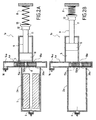
- the sliding chamber 14b of the shutter device 4b in communication with the combustion chamber 3 has a zone of embrittlement 18b, consisting for example of a lid frangible, located at the end of the race end of the drawer member 15b in its sliding chamber 14b.
- the drawer member 15b of the closure device 4b is same type as that integrated in the actuator 1 according to the first embodiment.
- This drawer piece 15b is therefore constituted by a hollow cylindrical part 150b having an opening on its side wall and having an open, cutting and tapered end 19b.
- the drawer piece 15b is placed in the enclosure of sliding 14b so that its end cutting edge is found next to the area of embrittlement 18b.
- the drawer piece 15b under the effect of gas produced by the ignition system 16, moves and closes with a part of its side wall, the passage 8 connecting the combustion chamber 3 to the sliding chamber 5. Moving the workpiece drawer 15b occurs until the end cutting 19b of said drawer member 15b comes to pierce the weakening zone 18b located for example at the end of run of sliding of the drawer part 15b. A communication is then established between the combustion 3 and the outside of the actuator 1b by through the drawer 15b whose part hollow 150b forms a duct deflecting the gases towards the hole formed after breaking the weakening zone 18b.
- the sliding chamber 5 is no longer powered in gas, the force generated by the pressure of the gases in the sliding chamber 5 and strength of resistance created by the spring R equilibrate, the piston 9 ceases then his race and remains frozen in this position.
- a anti-return device can ensure the maintaining the piston 9 in this position.
- the drawer piece 15c is similar to that described above with reference to the second mode of production.
- the drawer 15c is a piece full crossing by a channel 150c. Initially, the drawer piece 15c is positioned so that its channel 150c is placed opposite passage 8 formed between the combustion chamber 3 and the sliding chamber 5. Thus, the gases emitted by the pyrotechnic generator 7 can join the sliding chamber 5 and allow to advance the piston 9 in the chamber sliding 5.
- the body 2c (FIG. 4) of the actuator 1c comprises at the level of the combustion chamber 3 a calibrated 18c cap suitable for to break beyond a threshold pressure prevailing in the combustion chamber 3.
- the drawer 15c under the action of the gases emitted by the ignition system 16 of the device shutter 4c, moves and closes the passage 8 between the combustion chamber 3 and the chamber of sliding, preventing any entry of gases to inside the sliding chamber 5.
- the force generated by the gas pressure in the chamber of sliding 5 and the strength of resistance created by the spring R equilibrate and the piston 9 freezes in this position.
- a non-return device as described above with reference to FIGS.
- 5A and 5B may be adapted on the actuator 1c to avoid a decline of the piston 9.
- Generator 7 continues to produce gases which are held in the combustion chamber 3. The pressure therefore increases in the combustion chamber 3 and beyond a threshold pressure in the chamber of combustion 3, the calibrated seal 18c breaks, putting so in communication the combustion chamber 3 and the outside of the actuator 1c The gases present in the combustion chamber are thus evacuated to the outside through the hole formed on the body of the actuator after the rupture of the seal 18c calibrated.
- the pyrotechnic actuator as described above with reference to FIGS. 1A to 4 is a thrust effect variable.
- the amount of gas sent to the chamber of slide freezes the piston into a position determined.
- the range of motion of the piston is fully function of the resistance of the piece on which the thrust is performed.
- it is possible to obtain an actuator configurable race by directly integrating means resistance to movement of the piston of the actuator.
- the stiffness constant of this spring being known, the amplitude of displacement of the piston will be more solely dependent on the resistance of the piece on which the thrust is performed.
Applications Claiming Priority (2)
| Application Number | Priority Date | Filing Date | Title |
|---|---|---|---|
| FR0308476A FR2857421B1 (fr) | 2003-07-10 | 2003-07-10 | Actionneur pyrotechnique a effet de poussee variable |
| FR0308476 | 2003-07-10 |
Publications (2)
| Publication Number | Publication Date |
|---|---|
| EP1496268A1 true EP1496268A1 (de) | 2005-01-12 |
| EP1496268B1 EP1496268B1 (de) | 2006-04-05 |
Family
ID=33443262
Family Applications (1)
| Application Number | Title | Priority Date | Filing Date |
|---|---|---|---|
| EP04291466A Not-in-force EP1496268B1 (de) | 2003-07-10 | 2004-06-11 | Pyrotechnischer Stellantrieb mit variabler Schubkraft |
Country Status (7)
| Country | Link |
|---|---|
| US (1) | US7296504B2 (de) |
| EP (1) | EP1496268B1 (de) |
| JP (1) | JP3993587B2 (de) |
| AT (1) | ATE322622T1 (de) |
| DE (1) | DE602004000593T2 (de) |
| ES (1) | ES2262101T3 (de) |
| FR (1) | FR2857421B1 (de) |
Cited By (1)
| Publication number | Priority date | Publication date | Assignee | Title |
|---|---|---|---|---|
| FR2981443A1 (fr) * | 2011-10-17 | 2013-04-19 | Sme | Generateur de gaz muni d'un organe de securite pour les cas d'echauffements lents |
Families Citing this family (11)
| Publication number | Priority date | Publication date | Assignee | Title |
|---|---|---|---|---|
| EP1771664A2 (de) * | 2004-07-23 | 2007-04-11 | Delphi Technologies, Inc. | Pyrotechnischer aktor |
| FR2876425B1 (fr) * | 2004-10-07 | 2007-01-26 | Pyroalliance Sa | Actionneur pyrotechnique a effort modulable et a geometrie optimisee |
| FR2883606B1 (fr) * | 2005-03-24 | 2010-03-19 | Snpe Materiaux Energetiques | Actionneur pyrotechnique muni d'un organe regulateur de pression |
| DE102005051657A1 (de) | 2005-10-28 | 2007-05-03 | GM Global Technology Operations, Inc., Detroit | Pyrotechnischer Aktuator |
| JP4855242B2 (ja) * | 2006-12-27 | 2012-01-18 | 株式会社ダイセル | アクチュエータ |
| US7735405B2 (en) * | 2008-03-14 | 2010-06-15 | Autoliv Asp, Inc. | Pyrotechnic actuator for retracting a piston |
| DE202009008861U1 (de) * | 2009-06-27 | 2010-11-11 | Junghans Microtec Gmbh | Sicherungseinrichtung für ein Geschoss |
| US8534174B2 (en) * | 2010-09-27 | 2013-09-17 | Power Tool Institute | Pyrotechnic actuator and power cutting tool with safety reaction system having such pyrotechnic actuator |
| US9228815B2 (en) * | 2011-07-04 | 2016-01-05 | Omnitek Partners Llc | Very low-power actuation devices |
| US9618305B2 (en) * | 2012-04-24 | 2017-04-11 | Omnitek Partners Llc | Very low power actuation devices |
| US10501038B2 (en) * | 2017-10-16 | 2019-12-10 | Ford Global Technologies, Llc | Guide for seatbelt webbing that moves automatically in response to an oblique or far-side impact event to maintain occupant in proper orientation |
Citations (3)
| Publication number | Priority date | Publication date | Assignee | Title |
|---|---|---|---|---|
| JPS5079676A (de) * | 1973-11-22 | 1975-06-28 | ||
| DE3817042A1 (de) * | 1987-05-30 | 1988-12-15 | Volkswagen Ag | Pyrotechniche spannvorrichtung fuer eine fahrzeuginsassen-rueckhalteeinrichtung |
| EP0550321A1 (de) * | 1991-12-31 | 1993-07-07 | Thomson-Brandt Armements | Pyrotechnischen Stellkolben mit gedämpften Hub |
Family Cites Families (6)
| Publication number | Priority date | Publication date | Assignee | Title |
|---|---|---|---|---|
| US2935971A (en) * | 1958-01-09 | 1960-05-10 | Albert M Stott | Single cycle self retracting thruster |
| US3242666A (en) * | 1963-12-26 | 1966-03-29 | Carl R Peterson | Safe parachute pack opener with indicator |
| US4619199A (en) * | 1984-07-31 | 1986-10-28 | The United States Of America As Represented By The Secretary Of The Air Force | Safing and arming mechanism |
| FR2824875B1 (fr) | 2001-05-21 | 2004-01-02 | Pyroalliance | Actionneur pyrotechnique muni d'une rondelle de retenue |
| FR2857313B1 (fr) * | 2003-07-10 | 2006-11-24 | Pyroalliance | Dispositif d'amortissement du deplacement d'une piece impliquant un fil metallique |
| US6942261B2 (en) * | 2003-08-14 | 2005-09-13 | Autoliv Asp, Inc. | Linear actuator with an internal dampening mechanism |
-
2003
- 2003-07-10 FR FR0308476A patent/FR2857421B1/fr not_active Expired - Fee Related
-
2004
- 2004-06-11 EP EP04291466A patent/EP1496268B1/de not_active Not-in-force
- 2004-06-11 DE DE602004000593T patent/DE602004000593T2/de active Active
- 2004-06-11 ES ES04291466T patent/ES2262101T3/es active Active
- 2004-06-11 AT AT04291466T patent/ATE322622T1/de not_active IP Right Cessation
- 2004-06-14 US US10/865,847 patent/US7296504B2/en not_active Expired - Fee Related
- 2004-07-08 JP JP2004202044A patent/JP3993587B2/ja not_active Expired - Fee Related
Patent Citations (3)
| Publication number | Priority date | Publication date | Assignee | Title |
|---|---|---|---|---|
| JPS5079676A (de) * | 1973-11-22 | 1975-06-28 | ||
| DE3817042A1 (de) * | 1987-05-30 | 1988-12-15 | Volkswagen Ag | Pyrotechniche spannvorrichtung fuer eine fahrzeuginsassen-rueckhalteeinrichtung |
| EP0550321A1 (de) * | 1991-12-31 | 1993-07-07 | Thomson-Brandt Armements | Pyrotechnischen Stellkolben mit gedämpften Hub |
Cited By (3)
| Publication number | Priority date | Publication date | Assignee | Title |
|---|---|---|---|---|
| FR2981443A1 (fr) * | 2011-10-17 | 2013-04-19 | Sme | Generateur de gaz muni d'un organe de securite pour les cas d'echauffements lents |
| WO2013057404A1 (fr) * | 2011-10-17 | 2013-04-25 | Herakles | Generateur de gaz muni d'un organe de securite pour les cas d'echauffements lents |
| US9228811B2 (en) | 2011-10-17 | 2016-01-05 | Herakles | Gas generator provided with a safety device for slow warm-ups |
Also Published As
| Publication number | Publication date |
|---|---|
| JP2005030594A (ja) | 2005-02-03 |
| EP1496268B1 (de) | 2006-04-05 |
| FR2857421A1 (fr) | 2005-01-14 |
| DE602004000593D1 (de) | 2006-05-18 |
| ES2262101T3 (es) | 2006-11-16 |
| JP3993587B2 (ja) | 2007-10-17 |
| US20050016371A1 (en) | 2005-01-27 |
| DE602004000593T2 (de) | 2006-11-30 |
| ATE322622T1 (de) | 2006-04-15 |
| FR2857421B1 (fr) | 2005-08-19 |
| US7296504B2 (en) | 2007-11-20 |
Similar Documents
| Publication | Publication Date | Title |
|---|---|---|
| EP1705383B1 (de) | Pyrotechnischer Aktor mit Druckregelorgan | |
| CA2696842C (fr) | Verin a course declenchee, notamment pour systeme de securite automobile de protection des pietons | |
| EP1496268B1 (de) | Pyrotechnischer Stellantrieb mit variabler Schubkraft | |
| EP2566758B1 (de) | Auslösbare verriegelungsvorrichtung zum verbinden von zwei trennbaren baugruppen | |
| EP1138957A1 (de) | Schockarmer, wiederaufladbarer Trennbolzen | |
| EP2093408A1 (de) | Tank mit Druckbeaufschlagung durch heisse Gase | |
| CA2717346C (fr) | Verin leve capot avec agencement de freinage en retour desamorcable | |
| EP1486697B1 (de) | Modulierbarer Dämpfer mit pyrotechnischen Gasen | |
| FR2852570A1 (fr) | Butee d'absorption de choc pour vehicule automobile | |
| EP1712434A1 (de) | Einziehbarer Stossdämpferanschlag für ein Kraftfahrzeug | |
| EP1495918B1 (de) | Stossabsorbierende Vorrichtung eines Fahrzeugteils mit einem Metallfaden | |
| LU87748A1 (fr) | Dispositif de neutralisation d'une soupape de pression residuelle d'une bouteille a gaz | |
| CA2566241C (fr) | Dispositif d'amortisseur a deceleration asservie, et son application a l'amortissement de la colonne de direction escamotable d'un vehicule automobile | |
| FR3016007A1 (fr) | Dispositif d'actionnement d'urgence notamment destine a un ouvrant d'aeronef | |
| EP1802871B1 (de) | Pyrotechnisches betätigungsglied mit steuerbarer kraft und optimierter geometrie | |
| EP2444319B1 (de) | Verteilungssystem eines Antriebsgases zur Versorgung eines pneumatischen Stellantriebs, Auswurfeinheit und entsprechendes Verteilungsverfahren | |
| EP2166233B1 (de) | Zylinder mit progressiver Wirkung | |
| FR2845446A1 (fr) | Dispositif d'absorption d'energie pour colonne de direction | |
| FR2901523A1 (fr) | "generateur de gaz pour dispositif de securite automobile et dispositif qui en est pourvu" | |
| FR2885584A1 (fr) | Dispositif de renforcement d'un element creux de carrosserie de vehicule automobile | |
| EP1518771B1 (de) | Hauptzylinder für Bremskreislauf | |
| FR2878211A1 (fr) | Actionneur pyrotechnique pour systeme de securite automobile | |
| FR2929126A1 (fr) | Dispositif d'ejection d'un fluide muni d'un dispositif anti-retour | |
| FR2556295A1 (fr) | Dispositif d'absorption d'energie pour le montage d'un pare-chocs sur un vehicule automobile | |
| EP1216907A1 (de) | Verbessertes Bremsbetätigungssystem mit Bremskraftverstärker und hydraulischer Rückwirkung |
Legal Events
| Date | Code | Title | Description |
|---|---|---|---|
| PUAI | Public reference made under article 153(3) epc to a published international application that has entered the european phase |
Free format text: ORIGINAL CODE: 0009012 |
|
| AK | Designated contracting states |
Kind code of ref document: A1 Designated state(s): AT BE BG CH CY CZ DE DK EE ES FI FR GB GR HU IE IT LI LU MC NL PL PT RO SE SI SK TR |
|
| AX | Request for extension of the european patent |
Extension state: AL HR LT LV MK |
|
| 17P | Request for examination filed |
Effective date: 20050712 |
|
| GRAP | Despatch of communication of intention to grant a patent |
Free format text: ORIGINAL CODE: EPIDOSNIGR1 |
|
| AKX | Designation fees paid |
Designated state(s): AT BE BG CH CY CZ DE DK EE ES FI FR GB GR HU IE IT LI LU MC NL PL PT RO SE SI SK TR |
|
| GRAS | Grant fee paid |
Free format text: ORIGINAL CODE: EPIDOSNIGR3 |
|
| GRAA | (expected) grant |
Free format text: ORIGINAL CODE: 0009210 |
|
| AK | Designated contracting states |
Kind code of ref document: B1 Designated state(s): AT BE BG CH CY CZ DE DK EE ES FI FR GB GR HU IE IT LI LU MC NL PL PT RO SE SI SK TR |
|
| PG25 | Lapsed in a contracting state [announced via postgrant information from national office to epo] |
Ref country code: FI Free format text: LAPSE BECAUSE OF FAILURE TO SUBMIT A TRANSLATION OF THE DESCRIPTION OR TO PAY THE FEE WITHIN THE PRESCRIBED TIME-LIMIT Effective date: 20060405 Ref country code: SK Free format text: LAPSE BECAUSE OF FAILURE TO SUBMIT A TRANSLATION OF THE DESCRIPTION OR TO PAY THE FEE WITHIN THE PRESCRIBED TIME-LIMIT Effective date: 20060405 Ref country code: AT Free format text: LAPSE BECAUSE OF FAILURE TO SUBMIT A TRANSLATION OF THE DESCRIPTION OR TO PAY THE FEE WITHIN THE PRESCRIBED TIME-LIMIT Effective date: 20060405 Ref country code: IE Free format text: LAPSE BECAUSE OF FAILURE TO SUBMIT A TRANSLATION OF THE DESCRIPTION OR TO PAY THE FEE WITHIN THE PRESCRIBED TIME-LIMIT Effective date: 20060405 Ref country code: PL Free format text: LAPSE BECAUSE OF FAILURE TO SUBMIT A TRANSLATION OF THE DESCRIPTION OR TO PAY THE FEE WITHIN THE PRESCRIBED TIME-LIMIT Effective date: 20060405 Ref country code: CZ Free format text: LAPSE BECAUSE OF FAILURE TO SUBMIT A TRANSLATION OF THE DESCRIPTION OR TO PAY THE FEE WITHIN THE PRESCRIBED TIME-LIMIT Effective date: 20060405 Ref country code: RO Free format text: LAPSE BECAUSE OF FAILURE TO SUBMIT A TRANSLATION OF THE DESCRIPTION OR TO PAY THE FEE WITHIN THE PRESCRIBED TIME-LIMIT Effective date: 20060405 Ref country code: SI Free format text: LAPSE BECAUSE OF FAILURE TO SUBMIT A TRANSLATION OF THE DESCRIPTION OR TO PAY THE FEE WITHIN THE PRESCRIBED TIME-LIMIT Effective date: 20060405 Ref country code: NL Free format text: LAPSE BECAUSE OF FAILURE TO SUBMIT A TRANSLATION OF THE DESCRIPTION OR TO PAY THE FEE WITHIN THE PRESCRIBED TIME-LIMIT Effective date: 20060405 |
|
| REG | Reference to a national code |
Ref country code: GB Ref legal event code: FG4D Free format text: NOT ENGLISH |
|
| REG | Reference to a national code |
Ref country code: CH Ref legal event code: EP |
|
| REG | Reference to a national code |
Ref country code: IE Ref legal event code: FG4D Free format text: LANGUAGE OF EP DOCUMENT: FRENCH |
|
| REF | Corresponds to: |
Ref document number: 602004000593 Country of ref document: DE Date of ref document: 20060518 Kind code of ref document: P |
|
| PG25 | Lapsed in a contracting state [announced via postgrant information from national office to epo] |
Ref country code: MC Free format text: LAPSE BECAUSE OF NON-PAYMENT OF DUE FEES Effective date: 20060630 |
|
| GBT | Gb: translation of ep patent filed (gb section 77(6)(a)/1977) |
Effective date: 20060612 |
|
| PG25 | Lapsed in a contracting state [announced via postgrant information from national office to epo] |
Ref country code: DK Free format text: LAPSE BECAUSE OF FAILURE TO SUBMIT A TRANSLATION OF THE DESCRIPTION OR TO PAY THE FEE WITHIN THE PRESCRIBED TIME-LIMIT Effective date: 20060705 |
|
| REG | Reference to a national code |
Ref country code: SE Ref legal event code: TRGR |
|
| PG25 | Lapsed in a contracting state [announced via postgrant information from national office to epo] |
Ref country code: PT Free format text: LAPSE BECAUSE OF FAILURE TO SUBMIT A TRANSLATION OF THE DESCRIPTION OR TO PAY THE FEE WITHIN THE PRESCRIBED TIME-LIMIT Effective date: 20060905 |
|
| NLV1 | Nl: lapsed or annulled due to failure to fulfill the requirements of art. 29p and 29m of the patents act | ||
| REG | Reference to a national code |
Ref country code: FR Ref legal event code: TP |
|
| REG | Reference to a national code |
Ref country code: IE Ref legal event code: FD4D |
|
| REG | Reference to a national code |
Ref country code: ES Ref legal event code: FG2A Ref document number: 2262101 Country of ref document: ES Kind code of ref document: T3 |
|
| REG | Reference to a national code |
Ref country code: GB Ref legal event code: 732E |
|
| REG | Reference to a national code |
Ref country code: ES Ref legal event code: PC2A |
|
| PLBE | No opposition filed within time limit |
Free format text: ORIGINAL CODE: 0009261 |
|
| STAA | Information on the status of an ep patent application or granted ep patent |
Free format text: STATUS: NO OPPOSITION FILED WITHIN TIME LIMIT |
|
| 26N | No opposition filed |
Effective date: 20070108 |
|
| BECA | Be: change of holder's address |
Owner name: *SNPE MATERIAUX ENERGETIQUES12 QUAI HENRI IV, F-75 Effective date: 20060405 |
|
| BECH | Be: change of holder |
Owner name: *SNPE MATERIAUX ENERGETIQUES Effective date: 20060405 |
|
| PG25 | Lapsed in a contracting state [announced via postgrant information from national office to epo] |
Ref country code: GR Free format text: LAPSE BECAUSE OF FAILURE TO SUBMIT A TRANSLATION OF THE DESCRIPTION OR TO PAY THE FEE WITHIN THE PRESCRIBED TIME-LIMIT Effective date: 20060706 |
|
| PG25 | Lapsed in a contracting state [announced via postgrant information from national office to epo] |
Ref country code: BG Free format text: LAPSE BECAUSE OF FAILURE TO SUBMIT A TRANSLATION OF THE DESCRIPTION OR TO PAY THE FEE WITHIN THE PRESCRIBED TIME-LIMIT Effective date: 20060705 Ref country code: EE Free format text: LAPSE BECAUSE OF FAILURE TO SUBMIT A TRANSLATION OF THE DESCRIPTION OR TO PAY THE FEE WITHIN THE PRESCRIBED TIME-LIMIT Effective date: 20060405 |
|
| PG25 | Lapsed in a contracting state [announced via postgrant information from national office to epo] |
Ref country code: LU Free format text: LAPSE BECAUSE OF NON-PAYMENT OF DUE FEES Effective date: 20060611 Ref country code: TR Free format text: LAPSE BECAUSE OF FAILURE TO SUBMIT A TRANSLATION OF THE DESCRIPTION OR TO PAY THE FEE WITHIN THE PRESCRIBED TIME-LIMIT Effective date: 20060405 Ref country code: HU Free format text: LAPSE BECAUSE OF FAILURE TO SUBMIT A TRANSLATION OF THE DESCRIPTION OR TO PAY THE FEE WITHIN THE PRESCRIBED TIME-LIMIT Effective date: 20061006 |
|
| PG25 | Lapsed in a contracting state [announced via postgrant information from national office to epo] |
Ref country code: CY Free format text: LAPSE BECAUSE OF FAILURE TO SUBMIT A TRANSLATION OF THE DESCRIPTION OR TO PAY THE FEE WITHIN THE PRESCRIBED TIME-LIMIT Effective date: 20060405 |
|
| REG | Reference to a national code |
Ref country code: CH Ref legal event code: PL |
|
| PG25 | Lapsed in a contracting state [announced via postgrant information from national office to epo] |
Ref country code: CH Free format text: LAPSE BECAUSE OF NON-PAYMENT OF DUE FEES Effective date: 20080630 Ref country code: LI Free format text: LAPSE BECAUSE OF NON-PAYMENT OF DUE FEES Effective date: 20080630 |
|
| REG | Reference to a national code |
Ref country code: FR Ref legal event code: CD Owner name: HERAKLES, FR Effective date: 20130213 Ref country code: FR Ref legal event code: CA Effective date: 20130213 |
|
| REG | Reference to a national code |
Ref country code: DE Ref legal event code: R082 Ref document number: 602004000593 Country of ref document: DE Representative=s name: CBDL PATENTANWAELTE, DE |
|
| REG | Reference to a national code |
Ref country code: DE Ref legal event code: R082 Ref document number: 602004000593 Country of ref document: DE Representative=s name: CBDL PATENTANWAELTE, DE Effective date: 20130528 Ref country code: DE Ref legal event code: R082 Ref document number: 602004000593 Country of ref document: DE Representative=s name: CBDL PATENTANWAELTE, DE Effective date: 20130513 Ref country code: DE Ref legal event code: R081 Ref document number: 602004000593 Country of ref document: DE Owner name: HERAKLES, FR Free format text: FORMER OWNER: SME, PARIS, FR Effective date: 20130528 Ref country code: DE Ref legal event code: R081 Ref document number: 602004000593 Country of ref document: DE Owner name: HERAKLES, FR Free format text: FORMER OWNER: SNPE MATERIAUX ENERGETIQUES, PARIS, FR Effective date: 20130513 |
|
| REG | Reference to a national code |
Ref country code: ES Ref legal event code: PC2A Owner name: HERAKLES Effective date: 20130708 |
|
| PGFP | Annual fee paid to national office [announced via postgrant information from national office to epo] |
Ref country code: ES Payment date: 20140617 Year of fee payment: 11 |
|
| PGFP | Annual fee paid to national office [announced via postgrant information from national office to epo] |
Ref country code: BE Payment date: 20140523 Year of fee payment: 11 |
|
| REG | Reference to a national code |
Ref country code: FR Ref legal event code: PLFP Year of fee payment: 13 |
|
| REG | Reference to a national code |
Ref country code: ES Ref legal event code: FD2A Effective date: 20160728 |
|
| PGFP | Annual fee paid to national office [announced via postgrant information from national office to epo] |
Ref country code: DE Payment date: 20160524 Year of fee payment: 13 Ref country code: GB Payment date: 20160527 Year of fee payment: 13 |
|
| PGFP | Annual fee paid to national office [announced via postgrant information from national office to epo] |
Ref country code: FR Payment date: 20160610 Year of fee payment: 13 Ref country code: SE Payment date: 20160527 Year of fee payment: 13 Ref country code: IT Payment date: 20160525 Year of fee payment: 13 |
|
| PG25 | Lapsed in a contracting state [announced via postgrant information from national office to epo] |
Ref country code: ES Free format text: LAPSE BECAUSE OF NON-PAYMENT OF DUE FEES Effective date: 20150612 |
|
| PG25 | Lapsed in a contracting state [announced via postgrant information from national office to epo] |
Ref country code: BE Free format text: LAPSE BECAUSE OF NON-PAYMENT OF DUE FEES Effective date: 20150630 |
|
| REG | Reference to a national code |
Ref country code: DE Ref legal event code: R119 Ref document number: 602004000593 Country of ref document: DE |
|
| REG | Reference to a national code |
Ref country code: SE Ref legal event code: EUG |
|
| GBPC | Gb: european patent ceased through non-payment of renewal fee |
Effective date: 20170611 |
|
| PG25 | Lapsed in a contracting state [announced via postgrant information from national office to epo] |
Ref country code: SE Free format text: LAPSE BECAUSE OF NON-PAYMENT OF DUE FEES Effective date: 20170612 |
|
| REG | Reference to a national code |
Ref country code: FR Ref legal event code: ST Effective date: 20180228 |
|
| PG25 | Lapsed in a contracting state [announced via postgrant information from national office to epo] |
Ref country code: DE Free format text: LAPSE BECAUSE OF NON-PAYMENT OF DUE FEES Effective date: 20180103 Ref country code: GB Free format text: LAPSE BECAUSE OF NON-PAYMENT OF DUE FEES Effective date: 20170611 |
|
| PG25 | Lapsed in a contracting state [announced via postgrant information from national office to epo] |
Ref country code: IT Free format text: LAPSE BECAUSE OF NON-PAYMENT OF DUE FEES Effective date: 20170611 Ref country code: FR Free format text: LAPSE BECAUSE OF NON-PAYMENT OF DUE FEES Effective date: 20170630 |