EP1496204B1 - Turbinenschaufel - Google Patents
Turbinenschaufel Download PDFInfo
- Publication number
- EP1496204B1 EP1496204B1 EP04252650A EP04252650A EP1496204B1 EP 1496204 B1 EP1496204 B1 EP 1496204B1 EP 04252650 A EP04252650 A EP 04252650A EP 04252650 A EP04252650 A EP 04252650A EP 1496204 B1 EP1496204 B1 EP 1496204B1
- Authority
- EP
- European Patent Office
- Prior art keywords
- channel
- bridge
- serpentine
- airfoil
- disposed
- Prior art date
- Legal status (The legal status is an assumption and is not a legal conclusion. Google has not performed a legal analysis and makes no representation as to the accuracy of the status listed.)
- Expired - Lifetime
Links
- 238000001816 cooling Methods 0.000 claims description 57
- 238000004891 communication Methods 0.000 claims description 15
- WYTGDNHDOZPMIW-RCBQFDQVSA-N alstonine Natural products C1=CC2=C3C=CC=CC3=NC2=C2N1C[C@H]1[C@H](C)OC=C(C(=O)OC)[C@H]1C2 WYTGDNHDOZPMIW-RCBQFDQVSA-N 0.000 claims description 3
- 238000007599 discharging Methods 0.000 claims description 3
- 230000005465 channeling Effects 0.000 claims description 2
- 230000000295 complement effect Effects 0.000 claims description 2
- 239000007789 gas Substances 0.000 description 8
- 230000008901 benefit Effects 0.000 description 6
- 238000005266 casting Methods 0.000 description 5
- 239000000567 combustion gas Substances 0.000 description 5
- 230000001965 increasing effect Effects 0.000 description 5
- 230000002708 enhancing effect Effects 0.000 description 3
- 239000000463 material Substances 0.000 description 3
- 239000000919 ceramic Substances 0.000 description 2
- 239000002826 coolant Substances 0.000 description 2
- 229910000601 superalloy Inorganic materials 0.000 description 2
- 230000007704 transition Effects 0.000 description 2
- 230000002860 competitive effect Effects 0.000 description 1
- 230000009977 dual effect Effects 0.000 description 1
- 239000000284 extract Substances 0.000 description 1
- 239000000446 fuel Substances 0.000 description 1
- 230000010354 integration Effects 0.000 description 1
- 230000003993 interaction Effects 0.000 description 1
- 238000005495 investment casting Methods 0.000 description 1
- 238000002955 isolation Methods 0.000 description 1
- 238000004519 manufacturing process Methods 0.000 description 1
- 238000000034 method Methods 0.000 description 1
- 230000005012 migration Effects 0.000 description 1
- 238000013508 migration Methods 0.000 description 1
- 238000002156 mixing Methods 0.000 description 1
- 238000013021 overheating Methods 0.000 description 1
- 230000004044 response Effects 0.000 description 1
- 238000012546 transfer Methods 0.000 description 1
- 238000011144 upstream manufacturing Methods 0.000 description 1
Images


Classifications
-
- F—MECHANICAL ENGINEERING; LIGHTING; HEATING; WEAPONS; BLASTING
- F01—MACHINES OR ENGINES IN GENERAL; ENGINE PLANTS IN GENERAL; STEAM ENGINES
- F01D—NON-POSITIVE DISPLACEMENT MACHINES OR ENGINES, e.g. STEAM TURBINES
- F01D5/00—Blades; Blade-carrying members; Heating, heat-insulating, cooling or antivibration means on the blades or the members
- F01D5/12—Blades
- F01D5/14—Form or construction
- F01D5/20—Specially-shaped blade tips to seal space between tips and stator
-
- F—MECHANICAL ENGINEERING; LIGHTING; HEATING; WEAPONS; BLASTING
- F01—MACHINES OR ENGINES IN GENERAL; ENGINE PLANTS IN GENERAL; STEAM ENGINES
- F01D—NON-POSITIVE DISPLACEMENT MACHINES OR ENGINES, e.g. STEAM TURBINES
- F01D5/00—Blades; Blade-carrying members; Heating, heat-insulating, cooling or antivibration means on the blades or the members
- F01D5/12—Blades
- F01D5/14—Form or construction
- F01D5/18—Hollow blades, i.e. blades with cooling or heating channels or cavities; Heating, heat-insulating or cooling means on blades
- F01D5/182—Transpiration cooling
- F01D5/184—Blade walls being made of perforated sheet laminae
-
- F—MECHANICAL ENGINEERING; LIGHTING; HEATING; WEAPONS; BLASTING
- F01—MACHINES OR ENGINES IN GENERAL; ENGINE PLANTS IN GENERAL; STEAM ENGINES
- F01D—NON-POSITIVE DISPLACEMENT MACHINES OR ENGINES, e.g. STEAM TURBINES
- F01D5/00—Blades; Blade-carrying members; Heating, heat-insulating, cooling or antivibration means on the blades or the members
- F01D5/12—Blades
- F01D5/14—Form or construction
- F01D5/18—Hollow blades, i.e. blades with cooling or heating channels or cavities; Heating, heat-insulating or cooling means on blades
- F01D5/186—Film cooling
-
- Y—GENERAL TAGGING OF NEW TECHNOLOGICAL DEVELOPMENTS; GENERAL TAGGING OF CROSS-SECTIONAL TECHNOLOGIES SPANNING OVER SEVERAL SECTIONS OF THE IPC; TECHNICAL SUBJECTS COVERED BY FORMER USPC CROSS-REFERENCE ART COLLECTIONS [XRACs] AND DIGESTS
- Y02—TECHNOLOGIES OR APPLICATIONS FOR MITIGATION OR ADAPTATION AGAINST CLIMATE CHANGE
- Y02T—CLIMATE CHANGE MITIGATION TECHNOLOGIES RELATED TO TRANSPORTATION
- Y02T50/00—Aeronautics or air transport
- Y02T50/60—Efficient propulsion technologies, e.g. for aircraft
Definitions
- the present invention relates generally to gas turbine engines, and, more specifically, to turbine blade cooling therein.
- HPT high pressure turbine
- LPT low pressure turbine
- Engine performance or efficiency may be increased by increasing the maximum allowed operating temperature of the combustion gases that are discharged to the HPT which extracts energy therefrom. Furthermore, engines are continually being developed for increasing cruise duration and distance, for one exemplary commercial application for a supersonic business jet and for an exemplary military application such as a long range strike aircraft.
- the first stage rotor blades receive the hottest combustion gases from the combustor and are presently manufactured with state-of-the-art superalloy materials having enhanced strength and durability at elevated temperature. These blades may be configured from a myriad of different cooling features for differently cooling the various portions of the blades against the corresponding differences in heat loads thereto during operation.
- first stage turbine blades presently limit the maximum allowed turbine inlet temperature for obtaining a suitable useful life of the blades.
- the superalloy blades are typically manufactured as directionally solidified materials or monocrystal materials for maximizing the strength and life capability thereof under the hostile hot temperature environment in the gas turbine engine.
- a turbine blade includes a hollow airfoil integrally joined to a dovetail.
- the airfoil includes a perforate first bridge defining a flow channel behind the airfoil leading edge.
- a second bridge is spaced behind the first bridge and extends from a pressure sidewall of the airfoil short of the airfoil trailing edge.
- a third bridge has opposite ends joined to the pressure sidewall and the second bridge to define with the first bridge a supply channel for the leading edge channel, and defines with the second bridge a louver channel extending aft along the second bridge to its distal end at the pressure sidewall.
- Illustrated in Figure 1 is an exemplary first stage turbine rotor blade 10 for use in a gas turbine engine in a high pressure turbine immediately downstream from a combustor thereof.
- the blade may be used in an aircraft gas turbine engine configuration, or may also be used in non-aircraft derivatives thereof.
- the blade includes a hollow airfoil 12 extending radially in span outwardly from a supporting dovetail 14 joined together at a common platform 16.
- the dovetail may have any conventional configuration including dovetail lobes or tangs which mount the blade into a corresponding dovetail slot in the perimeter of a turbine rotor disk (not shown).
- the dovetail is joined to the integral platform by a shank therebetween.
- the airfoil 12 includes a concave pressure sidewall 18 and a laterally or circumferentially opposite convex sidewall 20.
- the two sidewalls are joined together at axially or chordally opposite leading and trailing edges 22,24, and are spaced apart therebetween.
- the airfoil sidewalls and edges extend radially in span from an inner root 26 to an outer tip 28.
- the dovetail is integrally joined to the airfoil at the platform disposed at the airfoil root which defines the radially inner boundary for the combustion gases which flow around the airfoil during operation.
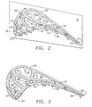
- Figures 2-4 illustrate three radial sectional views of the airfoil shown in Figure 1 near the airfoil root, at the mid-span or pitch section, and near the airfoil tip, respectively.
- the airfoil further includes a perforate first cold bridge 30 spaced behind or aft from the leading edge 22, and having opposite lateral ends integrally joined to the pressure and suction sidewalls 18,20 to define a leading edge flow channel 32 extending in radial span behind the leading edge and laterally bound by the surrounding portions of the sidewalls and the first bridge.
- the first bridge includes a row of impingement apertures 34 through which is channeled pressurized air 36 bled from a compressor (not shown) of the engine for providing blade cooling.
- the air firstly impinges the inside or backside of the airfoil leading edge for cooling thereof, with the spent impingement air then being discharged from the leading edge channel 32 through several rows of showerhead holes and gill holes 38 radiating outwardly therefrom along the two sidewalls in a conventional configuration.
- the airfoil further includes an imperforate second cold bridge 40 extending in radial span behind the first bridge 30 and spaced aft therefrom.
- the second bridge 40 extends integrally from the suction sidewall 20 and chordally aft to integrally join the pressure sidewall 18 before or short of the trailing edge 24 to define a first serpentine flow channel 42 laterally between the second bridge and the suction sidewall.
- An imperforate third cold bridge 44 extends in radial span between the first and second bridges 30,40 and is integrally joined at opposite lateral ends to the pressure sidewall 18 and the second bridge 40.
- the third bridge 44 defines with the first bridge 30 a supply flow channel 46 extending in radial span for channeling the pressurized air 36 through the impingement apertures of the first bridge for impingement cooling the backside of the airfoil leading edge.
- the third bridge 44 also defines with the second bridge 40 a gill or louver flow channel 48 extending axially aft along the second bridge to the distal end thereof at the pressure sidewall 18.
- the three cold bridges 30,40,44 define corresponding flow channels integrated in a new configuration for providing enhanced cooling of the airfoil during operation.
- the various cooling channels of the airfoil illustrated in the Figures will include various forms of turbulators (not shown) extending along the inner surfaces thereof as required for tripping the cooling airflow for enhancing heat transfer in a conventional manner.
- the integrated three-bridge configuration enhances cooling effectiveness of the limited cooling air.
- the suction sidewall 20 includes a row of film cooling apertures 50 disposed in flow communication with the supply channel 46 adjacent the second bridge 40.
- the third bridge 44 is preferably arcuate, or bowed convex, in the radial plane illustrated, inside the supply channel 46 which is correspondingly bowed concave arcuate in a general C-shape to guide the cooling air 36 laterally for discharge through the film cooling apertures 50.
- This unique configuration of the supply channel 46 guides the flow being channeled through the supply channel 46 closer to the suction sidewall 20 for enhanced cooling thereof, while air is also discharged through the impingement apertures 34 for impingement cooling the backside of the leading edge.
- the airfoil includes a radial elongate outlet slot 52 adjacent the distal end of the second bridge 40 and disposed in flow communication with the discharge end of the louver channel 48 for discharging a radially continuous film of cooling air therefrom.
- a particular advantage of the louver channel 48 is the isolation of the cold second bridge 40 from the adjacent portion of the pressure sidewall 18, with backside cooling of the pressure sidewall being effected by the axial flow of the cooling air 36 through the louver channel for discharge from the slot 52 thereof.
- the axially forward portion of the louver channel extends open in radial span for feeding the cooling air to a mesh pattern of pins 54 spaced apart from each other and integrally joined at opposite lateral ends to the second bridge 40 and to the pressure sidewall 18 forward of the outlet slot 52.
- the mesh pins 54 may have any suitable configuration, such as round or square for example, and provide a locally tortuous or serpentine cooling path between the cold second bridge 40 and the hot pressure sidewall. In this way, the cooling air may be channeled axially between the mesh pins 54 for collective discharge from the common radial slot 52 to provide continuous radial film cooling along the aft portion of the pressure sidewall for protecting the thin trailing edge portion of the airfoil.
- the supply channel 46 includes a first inlet 56 extending through the dovetail 14 to the blade root.
- the louver channel 48 includes a second inlet 58 extending through the dovetail behind the first inlet 56 and feeds the open forward end of the louver channel with the cooling air 36.
- the first serpentine flow channel 42 includes a third inlet 60 extending through the dovetail behind the second inlet. The three dovetail inlets provide independent portions of the cooling air to the corresponding cooling circuits fed thereby.
- the airfoil preferably also includes a slant tier second serpentine channel 62 disposed outward or above the louver channel 48 in flow communication with the radially open forward portion thereof which receives air from the second inlet 58.
- the second serpentine channel is formed by corresponding slanted bridges disposed obliquely from the radial or span axis of the airfoil.
- Figure 4 is a radial cross section of the airfoil through the second serpentine channel 62 with portions of the slant bridges hiding from view the first serpentine flow channel located therebelow.
- a particular advantage of integrating the slanted second serpentine channel 62 near the blade tip is the additional effectiveness thereof for the tip region of the airfoil.
- the first serpentine channel illustrated in Figure 1 preferably consists of three flow reversing legs, and two corresponding radial dividing bridges therebetween.
- the second serpentine channel 62 preferably consists of three flow reversing legs and two corresponding slanted or inclined dividing bridges therebetween.
- serpentine cooling from the midchord to the trailing edge region of the airfoil is provided from the root radially outwardly, and terminates in transition from above the mid-span of the airfoil at the midchord region thereof to the tip of the airfoil near the trailing edge.
- the slant tier second serpentine channel 62 correspondingly provides serpentine cooling thereabove and below the airfoil tip to complement the first serpentine cooling circuit.
- the airfoil further includes a recessed or hollow tip cap 64 defined by a recessed floor in surrounding extensions of the pressure and suction sidewalls which define thin squealer tips or ribs.
- the tip cap 64 has a plurality of floor apertures 66 disposed radially therethrough in flow communication with the leading edge channel 32, the supply channel 46, and the louver channel 48, through the common second serpentine channel 62.
- Cooling of the trailing edge region of the airfoil illustrated in Figure 1 is preferably provided by two forms of discharge holes therein.
- a row of outer trailing edge slots 68 is disposed in flow communication with the last leg of the first serpentine flow channel 42.
- the trailing edge slots 68 are inclined through the pressure sidewall 18 and terminate on the pressure sidewall short of or just before the actual trailing edge 24 itself. This permits the trailing edge 24 to be extremely thin for increasing aerodynamic efficiency of the airfoil in a conventional manner.
- outer trailing edge slots 68 are preferably disposed over a majority of the trailing edge from just above the airfoil root to just below the airfoil tip
- a short row of inner trailing edge apertures 70 is disposed in flow communication with the lower portion of the last leg of the first serpentine channel 42.
- the three exemplary inner trailing edge apertures 70 illustrated in Figure 1 extend chordally between the pressure and suction sidewalls 18,20, as illustrated in Figure 2, to terminate through the trailing edge 24 itself generally parallel between the two opposite sidewalls of the airfoil.
- the trailing edge 24 near the blade root is suitably thicker for accommodating the trailing edge apertures 70 extending therethrough, and correspondingly increases the strength of the airfoil at its junction with the platform 16.
- the airfoil may be made thinner and transition to the use of the pressure-side trailing edge cooling slots 68.
- the air provided to the trailing edge outlets is obtained from the last leg of the three-leg serpentine channel 42, the air has been heated during the initial legs of the serpentine. Accordingly, it may be desired to include a refresher hole 72 as illustrated in Figure 1 in the forward leg of the first serpentine channel 42 to directly bypass a portion of air from the third inlet 60 directly to the last leg of the first serpentine channel. In this way, relatively cool air may be directly provided to the last leg of the serpentine channel for mixing with the spent serpentine air therein for enhancing cooling performance of the trailing edge as desired.
- the slant tier serpentine channel 62 is located directly under the tip cap 64.
- the airfoil may additionally include an axial outer bridge 74 spaced radially inwardly from the tip cap and extending generally parallel thereto, and aft to the trailing edge 24.
- the outer bridge 74 defines a tip channel 76 disposed in flow communication with the second serpentine channel 62 for discharging air therefrom through a corresponding discharge aperture defined at the aft end of the tip channel, preferably terminating in the airfoil pressure side short of the trailing edge in the same manner as the trailing edge slots 68.
- the airfoil tip is additionally cooled by the introduction of the axial tip channel 76 which provides dedicated backside cooling of the tip floor from the spent air discharged from the second serpentine channel.
- the integration of the three cold bridges 30,40,44 correspondingly integrates the cooling circuits 32,42,46,48 for providing double-wall cooling with enhanced effectiveness.
- the configuration of these cold bridges also permits conventional casting of the airfoil using corresponding ceramic cores for the flow channels or cavities.
- the leading edge channel and the corresponding trailing edge channel can be formed in a one-piece core or in two separate simple cores.
- the middle flow channels or circuits therebetween may be formed in an independent core. These two or three cores may then be assembled together for conventional lost-wax casting.
- the integrated cold bridge configuration described above will result in a reasonable casting yield for limiting manufacturing costs.
- the second cold bridge 40 is centrally located in the airfoil generally along the camber line thereof and provides a strong central support having a lower bulk temperature during operation.
- the leading edge utilizes the cold first bridge 30 in a conventional configuration with corresponding performance benefits thereof.
- the third cold bridge 44 integrates the cooling circuits defined by the first and second cold bridges 30,40 and has the preferred convex profile for enhancing cooling of the suction sidewall.
- the mesh pins 54 of the louver channel 48 provide locally enhanced cooling of the opposite pressure sidewall against the relatively high heat load experienced thereby during operation.
- the bank or array of pins 54 create high turbulence in the cooling air being discharged therearound due to interaction of the intersecting air jets therein. And, the pins themselves conduct heat from the hot pressure sidewall to the relatively cold second bridge 40 forming a highly efficient heat exchanger.
- the common exit slot 52 for the mesh pins of the louver channel provides full radial coverage of the film cooling air within the limit of its span, and a correspondingly higher cooling film effectiveness downstream therefrom toward the trailing edge.
- the inclined three-pass serpentine channel 62 introduces strong turbulence of the cooling air flowing therethrough at the multiple turns therein, and produces effective cooling of the airfoil outer span to prevent overheating thereof from radial migration of the hot combustion gases outside the airfoil.
- the trailing edge preferably includes the dual cooling arrangement provided by the two types of trailing edge outlets 68,70 for maintaining strength of the trailing edge near the root with the center apertures 70 splitting the trailing edge itself, while thereabove the pressure-side outlet slots 68 maintain aerodynamic advantage over the majority of the trailing edge.
- a particular advantage of the inclined or slanted bridges of the second serpentine channel 62 illustrated in the two embodiments of Figures 1 and 5 is the additional structural stiffness provided thereby for reducing or preventing stripe modes of sidewall panel vibration, and higher order complex panel vibratory modes. And, in the Figure 5 embodiment, the introduction of the additional horizontal outer bridge 74 further increases the stiffness of the airfoil tip region for reducing these modes of vibratory response.
Landscapes
- Engineering & Computer Science (AREA)
- Mechanical Engineering (AREA)
- General Engineering & Computer Science (AREA)
- Turbine Rotor Nozzle Sealing (AREA)
Claims (10)
- Turbinenlaufschaufel (10), aufweisend:ein hohles Schaufelblatt (12) mit einer konkaven Druckseitenwand (18) und einer lateral gegenüberliegenden konvexen Seitenwand (20), die miteinander an in Sehnenrichtung gegenüberliegenden sich in Höhenrichtung von einem Fuß (26) zu einer Spitze (28) erstreckenden Vorder- und Hinterkanten (22, 24) verbunden sind;einem Schwalbenschwanz (14), der in einem Stück mit dem Schaufelblatt an dem Fuß verbunden ist;wobei das Schaufelblatt ferner eine perforierte erste Brücke (30) enthält, die in einem Abstand hinter der Vorderkante angeordnet und in einem Stück mit den Druck- und Saugseitenwänden (18, 20) verbunden ist, um einen Vorderkantenkanal (32) dazwischen zu definieren, dadurch gekennzeichnet, dass
das Schaufelblatt ferner eine nicht perforierte zweite Kaltbrücke (40) enthält, die hinter der ersten Brücke in einem Abstand angeordnet ist und sich in einem Stück von der Saugseitenwand (20) in Sehnenrichtung nach hinten erstreckt, um sich in einem Stück mit der Druckseitenwand (18) vor der Hinterkante (24) zu vereinen, um einen ersten Serpentinenströmungskanal (42), angrenzend an die Saugseitenwand zu definieren; und
das Schaufelblatt ferner eine nicht perforierte dritte Brücke (44) enthält, die zwischen den ersten und zweiten Brücken (30, 40) angeordnet ist, und in einem Stück an gegenüberliegenden Enden mit der Druckseitenwand (18) und der zweiten Brücke (40) in einem konvexen Profil verbunden ist, um mit der ersten Brücke (30) einen komplementären konkaven Zuführungskanal (46) zu definieren, um Luft (36) durch die erste Brücke hindurchzuleiten, und um mit der zweiten Brücke (40) einen Luftschlitzkanal (48) zu definieren, der sich axial dahinter daran entlang zu deren distalen Ende an der Druckseitenwand (18) erstreckt. - Laufschaufel nach Anspruch 1, wobei die Druckseitenwand (18) angrenzend an das distale Ende der zweiten Brücke (40) in Strömungsverbindung mit dem Luftschlitzkanal (48) einen länglichen Auslassschlitz (52) enthält.
- Laufschaufel nach Anspruch 2, wobei:der Zuführungskanal (46) einen ersten Einlass (56) enthält, der sich durch den Schwalbenschwanz (14) verlaufend erstreckt;der Luftschlitzkanal (48) einen zweiten Einlass (58) enthält, der sich hinter dem ersten Einlass verlaufend durch den Schwalbenschwanz erstreckt; undder erste Serpentinenströmungskanal (46) einen dritten Einlass (60) enthält, der sich hinter dem zweiten Einlass durch den Schwalbenschwanz erstreckt.
- Laufschaufel nach Anspruch 3, welche ferner eine ausgesparte Spitzenkappe (64) mit mehreren durch sie verlaufenden Bodenöffnungen (66) aufweist, die mit dem Vorderkantenkanal (32), dem Zuführungskanal (46) und dem Luftschlitzkanal (48) in Strömungsverbindung angeordnet ist.
- Laufschaufel nach Anspruch 4, wobei:die Saugseitenwand (20) eine erste Reihe von Filmkühlöffnungen (50) enthält, die mit dem Zuführungskanal (46) angrenzend an die zweite Brücke (40) in Strömungsverbindung angeordnet sind; unddie dritte Brücke (44) innerhalb des Zuführungskanals (46) konvex ist, um die Luft zu den Filmkühlungsöffnungen (50) zu führen.
- Laufschaufel nach Anspruch 5, wobei der Luftschlitzkanal (48) ein Gittermuster von Stiften (54) enthält, die voneinander beabstandet und in einem Stück an gegenüberliegenden Enden mit der zweiten Brücke (40) und mit der Druckseitenwand (18) vor dem Auslassschlitz (52) verbunden sind, um eine lokale Serpentinengitterkühlung der Druckseitenwand bereitzustellen.
- Laufschaufel nach Anspruch 6, welche ferner einen zweiten Serpentinenströmungskanal (62) mit schräger Ebene aufweist, der oberhalb des Luftschlitzkanals (48) in Strömungsverbindung mit diesem angeordnet ist.
- Laufschaufel nach Anspruch 7, wobei der zweite Serpentinenkanal (62) in einem hinteren Teil über dem ersten Serpentinenkanal (42) angeordnet ist.
- Laufschaufel nach Anspruch 7, wobei:der erste Serpentinenkanal (42) aus drei Strömungsumkehrschenkeln und der zweite Serpentinenkanal (62) aus drei Strömungsumkehrschenkeln besteht; undder erste Serpentinenkanal (42) ein Auffrischungsloch (62) in seinem letzten Schenkel enthält, das mit dem dritten Einlass (60) in Strömungsverbindung angeordnet ist.
- Laufschaufel nach Anspruch 7, ferner aufweisend:eine äußere Brücke (74), die nach innen gerichtet von der Spitzenkappe (64) in Abstand angeordnet ist, um einen Spitzenkanal (76) zu definieren, der mit den zweiten Serpentinenkanal (62) in Strömungsverbindung angeordnet ist, um Luft daraus durch eine entsprechende Auslassöffnung an der Hinterkante (24) auszugeben;eine Reihe von äußeren Hinterkantenschlitzen (68), die mit dem ersten Serpentinenkanal (42) in Strömungsverbindung angeordnet sind und auf der Druckseitenwand (18) des Schaufelblattes vor der Hinterkante enden; undeine Reihe von inneren Hinterkantenöffnungen (70), die mit dem ersten Serpentinenkanal (42) in Strömungsverbindung angeordnet sind und sich in Sehnenrichtung zwischen den Druck- und Saugseitenwänden (18, 20) erstrecken, um durch die Hinterkante hindurchtretend zu enden.
Applications Claiming Priority (2)
| Application Number | Priority Date | Filing Date | Title |
|---|---|---|---|
| US616023 | 1990-11-21 | ||
| US10/616,023 US6832889B1 (en) | 2003-07-09 | 2003-07-09 | Integrated bridge turbine blade |
Publications (2)
| Publication Number | Publication Date |
|---|---|
| EP1496204A1 EP1496204A1 (de) | 2005-01-12 |
| EP1496204B1 true EP1496204B1 (de) | 2006-04-12 |
Family
ID=33452671
Family Applications (1)
| Application Number | Title | Priority Date | Filing Date |
|---|---|---|---|
| EP04252650A Expired - Lifetime EP1496204B1 (de) | 2003-07-09 | 2004-05-06 | Turbinenschaufel |
Country Status (4)
| Country | Link |
|---|---|
| US (1) | US6832889B1 (de) |
| EP (1) | EP1496204B1 (de) |
| JP (1) | JP4546760B2 (de) |
| DE (1) | DE602004000633T2 (de) |
Families Citing this family (72)
| Publication number | Priority date | Publication date | Assignee | Title |
|---|---|---|---|---|
| US6981840B2 (en) * | 2003-10-24 | 2006-01-03 | General Electric Company | Converging pin cooled airfoil |
| US6984103B2 (en) * | 2003-11-20 | 2006-01-10 | General Electric Company | Triple circuit turbine blade |
| DE102004002327A1 (de) * | 2004-01-16 | 2005-08-04 | Alstom Technology Ltd | Gekühlte Schaufel für eine Gasturbine |
| US7270515B2 (en) * | 2005-05-26 | 2007-09-18 | Siemens Power Generation, Inc. | Turbine airfoil trailing edge cooling system with segmented impingement ribs |
| US7296972B2 (en) * | 2005-12-02 | 2007-11-20 | Siemens Power Generation, Inc. | Turbine airfoil with counter-flow serpentine channels |
| US7296973B2 (en) * | 2005-12-05 | 2007-11-20 | General Electric Company | Parallel serpentine cooled blade |
| US7293961B2 (en) * | 2005-12-05 | 2007-11-13 | General Electric Company | Zigzag cooled turbine airfoil |
| US7507073B2 (en) * | 2006-02-24 | 2009-03-24 | General Electric Company | Methods and apparatus for assembling a steam turbine bucket |
| US20100247328A1 (en) * | 2006-06-06 | 2010-09-30 | United Technologies Corporation | Microcircuit cooling for blades |
| US7549843B2 (en) * | 2006-08-24 | 2009-06-23 | Siemens Energy, Inc. | Turbine airfoil cooling system with axial flowing serpentine cooling chambers |
| US7625178B2 (en) * | 2006-08-30 | 2009-12-01 | Honeywell International Inc. | High effectiveness cooled turbine blade |
| US20080085193A1 (en) * | 2006-10-05 | 2008-04-10 | Siemens Power Generation, Inc. | Turbine airfoil cooling system with enhanced tip corner cooling channel |
| US7530789B1 (en) * | 2006-11-16 | 2009-05-12 | Florida Turbine Technologies, Inc. | Turbine blade with a serpentine flow and impingement cooling circuit |
| US8591189B2 (en) * | 2006-11-20 | 2013-11-26 | General Electric Company | Bifeed serpentine cooled blade |
| US7645122B1 (en) * | 2006-12-01 | 2010-01-12 | Florida Turbine Technologies, Inc. | Turbine rotor blade with a nested parallel serpentine flow cooling circuit |
| US7762774B2 (en) | 2006-12-15 | 2010-07-27 | Siemens Energy, Inc. | Cooling arrangement for a tapered turbine blade |
| US7731481B2 (en) * | 2006-12-18 | 2010-06-08 | United Technologies Corporation | Airfoil cooling with staggered refractory metal core microcircuits |
| US7670113B1 (en) | 2007-05-31 | 2010-03-02 | Florida Turbine Technologies, Inc. | Turbine airfoil with serpentine trailing edge cooling circuit |
| US7836703B2 (en) * | 2007-06-20 | 2010-11-23 | General Electric Company | Reciprocal cooled turbine nozzle |
| US8016563B1 (en) * | 2007-12-21 | 2011-09-13 | Florida Turbine Technologies, Inc. | Turbine blade with tip turn cooling |
| FR2933884B1 (fr) * | 2008-07-16 | 2012-07-27 | Snecma | Procede de fabrication d'une piece d'aubage. |
| US8408866B2 (en) * | 2008-11-17 | 2013-04-02 | Rolls-Royce Corporation | Apparatus and method for cooling a turbine airfoil arrangement in a gas turbine engine |
| US8167558B2 (en) * | 2009-01-19 | 2012-05-01 | Siemens Energy, Inc. | Modular serpentine cooling systems for turbine engine components |
| US8061990B1 (en) * | 2009-03-13 | 2011-11-22 | Florida Turbine Technologies, Inc. | Turbine rotor blade with low cooling flow |
| US8123481B1 (en) * | 2009-06-17 | 2012-02-28 | Florida Turbine Technologies, Inc. | Turbine blade with dual serpentine cooling |
| CN102182518B (zh) * | 2011-06-08 | 2013-09-04 | 河南科技大学 | 一种涡轮冷却叶片 |
| US8840370B2 (en) | 2011-11-04 | 2014-09-23 | General Electric Company | Bucket assembly for turbine system |
| US20150110611A1 (en) * | 2012-05-31 | 2015-04-23 | General Electric Company | Airfoil cooling circuit and corresponding airfoil |
| FR2995342B1 (fr) * | 2012-09-13 | 2018-03-16 | Safran Aircraft Engines | Aube refroidie de turbine haute pression |
| US9447692B1 (en) * | 2012-11-28 | 2016-09-20 | S&J Design Llc | Turbine rotor blade with tip cooling |
| US8920123B2 (en) | 2012-12-14 | 2014-12-30 | Siemens Aktiengesellschaft | Turbine blade with integrated serpentine and axial tip cooling circuits |
| US9995149B2 (en) * | 2013-12-30 | 2018-06-12 | General Electric Company | Structural configurations and cooling circuits in turbine blades |
| US10307817B2 (en) * | 2014-10-31 | 2019-06-04 | United Technologies Corporation | Additively manufactured casting articles for manufacturing gas turbine engine parts |
| US10040115B2 (en) * | 2014-10-31 | 2018-08-07 | United Technologies Corporation | Additively manufactured casting articles for manufacturing gas turbine engine parts |
| EP3029414A1 (de) * | 2014-12-01 | 2016-06-08 | Siemens Aktiengesellschaft | Turbinenschaufel, Verfahren zu ihrer Herstellung und Verfahren zum Ermitteln der Lage eines beim Gießen einer Turbinenschaufel verwendeten Gusskerns |
| US10174620B2 (en) | 2015-10-15 | 2019-01-08 | General Electric Company | Turbine blade |
| US10208605B2 (en) | 2015-10-15 | 2019-02-19 | General Electric Company | Turbine blade |
| US10443398B2 (en) | 2015-10-15 | 2019-10-15 | General Electric Company | Turbine blade |
| US10370978B2 (en) | 2015-10-15 | 2019-08-06 | General Electric Company | Turbine blade |
| US9950358B2 (en) | 2015-11-19 | 2018-04-24 | General Electric Company | Compositions for cores used in investment casting |
| US10060269B2 (en) | 2015-12-21 | 2018-08-28 | General Electric Company | Cooling circuits for a multi-wall blade |
| US10119405B2 (en) | 2015-12-21 | 2018-11-06 | General Electric Company | Cooling circuit for a multi-wall blade |
| GB201610783D0 (en) | 2016-06-21 | 2016-08-03 | Rolls Royce Plc | Trailing edge ejection cooling |
| US10208607B2 (en) | 2016-08-18 | 2019-02-19 | General Electric Company | Cooling circuit for a multi-wall blade |
| US10221696B2 (en) | 2016-08-18 | 2019-03-05 | General Electric Company | Cooling circuit for a multi-wall blade |
| US10227877B2 (en) | 2016-08-18 | 2019-03-12 | General Electric Company | Cooling circuit for a multi-wall blade |
| US10208608B2 (en) * | 2016-08-18 | 2019-02-19 | General Electric Company | Cooling circuit for a multi-wall blade |
| US10267162B2 (en) | 2016-08-18 | 2019-04-23 | General Electric Company | Platform core feed for a multi-wall blade |
| US10450950B2 (en) * | 2016-10-26 | 2019-10-22 | General Electric Company | Turbomachine blade with trailing edge cooling circuit |
| US10563521B2 (en) | 2016-12-05 | 2020-02-18 | United Technologies Corporation | Aft flowing serpentine cavities and cores for airfoils of gas turbine engines |
| US10815800B2 (en) | 2016-12-05 | 2020-10-27 | Raytheon Technologies Corporation | Radially diffused tip flag |
| US10465529B2 (en) | 2016-12-05 | 2019-11-05 | United Technologies Corporation | Leading edge hybrid cavities and cores for airfoils of gas turbine engine |
| US10989056B2 (en) | 2016-12-05 | 2021-04-27 | Raytheon Technologies Corporation | Integrated squealer pocket tip and tip shelf with hybrid and tip flag core |
| US11015529B2 (en) | 2016-12-23 | 2021-05-25 | General Electric Company | Feature based cooling using in wall contoured cooling passage |
| KR101901682B1 (ko) | 2017-06-20 | 2018-09-27 | 두산중공업 주식회사 | 제이 타입 캔틸레버드 베인 및 이를 포함하는 가스터빈 |
| US20190060982A1 (en) | 2017-08-29 | 2019-02-28 | General Electric Company | Carbon fibers in ceramic cores for investment casting |
| FR3079262B1 (fr) * | 2018-03-23 | 2022-07-22 | Safran Helicopter Engines | Aube fixe de turbine a refroidissement par impacts de jets d'air |
| US10941663B2 (en) | 2018-05-07 | 2021-03-09 | Raytheon Technologies Corporation | Airfoil having improved leading edge cooling scheme and damage resistance |
| US10907479B2 (en) | 2018-05-07 | 2021-02-02 | Raytheon Technologies Corporation | Airfoil having improved leading edge cooling scheme and damage resistance |
| US10787932B2 (en) * | 2018-07-13 | 2020-09-29 | Honeywell International Inc. | Turbine blade with dust tolerant cooling system |
| MX2021000604A (es) * | 2018-07-18 | 2021-07-15 | Poly6 Tech Inc | Articulos y metodos de fabricacion. |
| US11499433B2 (en) | 2018-12-18 | 2022-11-15 | General Electric Company | Turbine engine component and method of cooling |
| US10767492B2 (en) | 2018-12-18 | 2020-09-08 | General Electric Company | Turbine engine airfoil |
| US11566527B2 (en) | 2018-12-18 | 2023-01-31 | General Electric Company | Turbine engine airfoil and method of cooling |
| US11174736B2 (en) | 2018-12-18 | 2021-11-16 | General Electric Company | Method of forming an additively manufactured component |
| US11352889B2 (en) | 2018-12-18 | 2022-06-07 | General Electric Company | Airfoil tip rail and method of cooling |
| US10844728B2 (en) | 2019-04-17 | 2020-11-24 | General Electric Company | Turbine engine airfoil with a trailing edge |
| CN111022127B (zh) * | 2019-11-29 | 2021-12-03 | 大连理工大学 | 一种涡轮叶片尾缘曲线式排气劈缝结构 |
| US11629601B2 (en) * | 2020-03-31 | 2023-04-18 | General Electric Company | Turbomachine rotor blade with a cooling circuit having an offset rib |
| US11220912B2 (en) * | 2020-04-16 | 2022-01-11 | Raytheon Technologies Corporation | Airfoil with y-shaped rib |
| US11814965B2 (en) | 2021-11-10 | 2023-11-14 | General Electric Company | Turbomachine blade trailing edge cooling circuit with turn passage having set of obstructions |
| GB2628416A (en) * | 2023-03-24 | 2024-09-25 | Solar Turbines Inc | Turbine blade for use in gas turbine engine |
Family Cites Families (15)
| Publication number | Priority date | Publication date | Assignee | Title |
|---|---|---|---|---|
| US5165852A (en) | 1990-12-18 | 1992-11-24 | General Electric Company | Rotation enhanced rotor blade cooling using a double row of coolant passageways |
| US5156526A (en) | 1990-12-18 | 1992-10-20 | General Electric Company | Rotation enhanced rotor blade cooling using a single row of coolant passageways |
| US5813835A (en) | 1991-08-19 | 1998-09-29 | The United States Of America As Represented By The Secretary Of The Air Force | Air-cooled turbine blade |
| US5690472A (en) | 1992-02-03 | 1997-11-25 | General Electric Company | Internal cooling of turbine airfoil wall using mesh cooling hole arrangement |
| US5660524A (en) | 1992-07-13 | 1997-08-26 | General Electric Company | Airfoil blade having a serpentine cooling circuit and impingement cooling |
| US5356265A (en) * | 1992-08-25 | 1994-10-18 | General Electric Company | Chordally bifurcated turbine blade |
| US5387085A (en) | 1994-01-07 | 1995-02-07 | General Electric Company | Turbine blade composite cooling circuit |
| US5591007A (en) | 1995-05-31 | 1997-01-07 | General Electric Company | Multi-tier turbine airfoil |
| US5927946A (en) * | 1997-09-29 | 1999-07-27 | General Electric Company | Turbine blade having recuperative trailing edge tip cooling |
| US5967752A (en) | 1997-12-31 | 1999-10-19 | General Electric Company | Slant-tier turbine airfoil |
| US6183198B1 (en) * | 1998-11-16 | 2001-02-06 | General Electric Company | Airfoil isolated leading edge cooling |
| US6168381B1 (en) * | 1999-06-29 | 2001-01-02 | General Electric Company | Airfoil isolated leading edge cooling |
| US6254334B1 (en) | 1999-10-05 | 2001-07-03 | United Technologies Corporation | Method and apparatus for cooling a wall within a gas turbine engine |
| US6402470B1 (en) | 1999-10-05 | 2002-06-11 | United Technologies Corporation | Method and apparatus for cooling a wall within a gas turbine engine |
| US6416284B1 (en) * | 2000-11-03 | 2002-07-09 | General Electric Company | Turbine blade for gas turbine engine and method of cooling same |
-
2003
- 2003-07-09 US US10/616,023 patent/US6832889B1/en not_active Expired - Fee Related
-
2004
- 2004-05-06 DE DE602004000633T patent/DE602004000633T2/de not_active Expired - Lifetime
- 2004-05-06 EP EP04252650A patent/EP1496204B1/de not_active Expired - Lifetime
- 2004-05-07 JP JP2004138380A patent/JP4546760B2/ja not_active Expired - Fee Related
Also Published As
| Publication number | Publication date |
|---|---|
| US6832889B1 (en) | 2004-12-21 |
| JP4546760B2 (ja) | 2010-09-15 |
| DE602004000633T2 (de) | 2007-05-03 |
| DE602004000633D1 (de) | 2006-05-24 |
| JP2005030387A (ja) | 2005-02-03 |
| US20050008487A1 (en) | 2005-01-13 |
| EP1496204A1 (de) | 2005-01-12 |
Similar Documents
| Publication | Publication Date | Title |
|---|---|---|
| EP1496204B1 (de) | Turbinenschaufel | |
| CA2477402C (en) | Converging pin cooled airfoil | |
| US7011502B2 (en) | Thermal shield turbine airfoil | |
| EP1001137B1 (de) | Gasturbinenschaufel mit serpentinenförmigen Kühlkanälen | |
| CA2668605C (en) | Crossflow turbine airfoil | |
| US7293961B2 (en) | Zigzag cooled turbine airfoil | |
| EP1327747B1 (de) | Prallkühlung für Hinterkanten einer Turbinenschaufel | |
| US6984103B2 (en) | Triple circuit turbine blade | |
| EP1544411B1 (de) | Verfahren zur Frequenzverstimmung einer Turbinenschaufel | |
| US6607355B2 (en) | Turbine airfoil with enhanced heat transfer | |
| CA2327857C (en) | Turbine nozzle with sloped film cooling | |
| EP1645722B1 (de) | Turbinenschaufel mit gestuften Kühlluft-Auslassschlitzen | |
| US6890153B2 (en) | Castellated turbine airfoil | |
| EP3006670B1 (de) | Turbinenschaufeln mit angehobenen rippenturbulatorstrukturen | |
| JP2005299636A (ja) | カスケードインピンジメント冷却式翼形部 | |
| WO2014011276A2 (en) | Turbine airfoil trailing edge bifurcated cooling holes | |
| WO2014011253A2 (en) | Turbine airfoil trailing edge cooling slots |
Legal Events
| Date | Code | Title | Description |
|---|---|---|---|
| PUAI | Public reference made under article 153(3) epc to a published international application that has entered the european phase |
Free format text: ORIGINAL CODE: 0009012 |
|
| AK | Designated contracting states |
Kind code of ref document: A1 Designated state(s): AT BE BG CH CY CZ DE DK EE ES FI FR GB GR HU IE IT LI LU MC NL PL PT RO SE SI SK TR |
|
| AX | Request for extension of the european patent |
Extension state: AL HR LT LV MK |
|
| 17P | Request for examination filed |
Effective date: 20050712 |
|
| GRAP | Despatch of communication of intention to grant a patent |
Free format text: ORIGINAL CODE: EPIDOSNIGR1 |
|
| AKX | Designation fees paid |
Designated state(s): DE GB IT |
|
| GRAS | Grant fee paid |
Free format text: ORIGINAL CODE: EPIDOSNIGR3 |
|
| GRAA | (expected) grant |
Free format text: ORIGINAL CODE: 0009210 |
|
| AK | Designated contracting states |
Kind code of ref document: B1 Designated state(s): DE GB IT |
|
| REG | Reference to a national code |
Ref country code: GB Ref legal event code: FG4D |
|
| REF | Corresponds to: |
Ref document number: 602004000633 Country of ref document: DE Date of ref document: 20060524 Kind code of ref document: P |
|
| PLBE | No opposition filed within time limit |
Free format text: ORIGINAL CODE: 0009261 |
|
| STAA | Information on the status of an ep patent application or granted ep patent |
Free format text: STATUS: NO OPPOSITION FILED WITHIN TIME LIMIT |
|
| 26N | No opposition filed |
Effective date: 20070115 |
|
| PGFP | Annual fee paid to national office [announced via postgrant information from national office to epo] |
Ref country code: DE Payment date: 20100527 Year of fee payment: 7 Ref country code: IT Payment date: 20100525 Year of fee payment: 7 |
|
| PGFP | Annual fee paid to national office [announced via postgrant information from national office to epo] |
Ref country code: GB Payment date: 20100525 Year of fee payment: 7 |
|
| GBPC | Gb: european patent ceased through non-payment of renewal fee |
Effective date: 20110506 |
|
| PG25 | Lapsed in a contracting state [announced via postgrant information from national office to epo] |
Ref country code: IT Free format text: LAPSE BECAUSE OF NON-PAYMENT OF DUE FEES Effective date: 20110506 |
|
| REG | Reference to a national code |
Ref country code: DE Ref legal event code: R119 Ref document number: 602004000633 Country of ref document: DE Effective date: 20111201 |
|
| PG25 | Lapsed in a contracting state [announced via postgrant information from national office to epo] |
Ref country code: GB Free format text: LAPSE BECAUSE OF NON-PAYMENT OF DUE FEES Effective date: 20110506 |
|
| PG25 | Lapsed in a contracting state [announced via postgrant information from national office to epo] |
Ref country code: DE Free format text: LAPSE BECAUSE OF NON-PAYMENT OF DUE FEES Effective date: 20111201 |