EP1496164A1 - Positive connection of the fitting of a conduit - Google Patents
Positive connection of the fitting of a conduit Download PDFInfo
- Publication number
- EP1496164A1 EP1496164A1 EP03023338A EP03023338A EP1496164A1 EP 1496164 A1 EP1496164 A1 EP 1496164A1 EP 03023338 A EP03023338 A EP 03023338A EP 03023338 A EP03023338 A EP 03023338A EP 1496164 A1 EP1496164 A1 EP 1496164A1
- Authority
- EP
- European Patent Office
- Prior art keywords
- pipe
- positive connection
- connecting piece
- connection according
- hose
- Prior art date
- Legal status (The legal status is an assumption and is not a legal conclusion. Google has not performed a legal analysis and makes no representation as to the accuracy of the status listed.)
- Granted
Links
Images
Classifications
-
- F—MECHANICAL ENGINEERING; LIGHTING; HEATING; WEAPONS; BLASTING
- F16—ENGINEERING ELEMENTS AND UNITS; GENERAL MEASURES FOR PRODUCING AND MAINTAINING EFFECTIVE FUNCTIONING OF MACHINES OR INSTALLATIONS; THERMAL INSULATION IN GENERAL
- F16K—VALVES; TAPS; COCKS; ACTUATING-FLOATS; DEVICES FOR VENTING OR AERATING
- F16K11/00—Multiple-way valves, e.g. mixing valves; Pipe fittings incorporating such valves
- F16K11/02—Multiple-way valves, e.g. mixing valves; Pipe fittings incorporating such valves with all movable sealing faces moving as one unit
- F16K11/06—Multiple-way valves, e.g. mixing valves; Pipe fittings incorporating such valves with all movable sealing faces moving as one unit comprising only sliding valves, i.e. sliding closure elements
- F16K11/078—Multiple-way valves, e.g. mixing valves; Pipe fittings incorporating such valves with all movable sealing faces moving as one unit comprising only sliding valves, i.e. sliding closure elements with pivoted and linearly movable closure members
- F16K11/0782—Single-lever operated mixing valves with closure members having flat sealing faces
- F16K11/0787—Single-lever operated mixing valves with closure members having flat sealing faces with both the supply and the discharge passages being on the same side of the closure members
-
- E—FIXED CONSTRUCTIONS
- E03—WATER SUPPLY; SEWERAGE
- E03C—DOMESTIC PLUMBING INSTALLATIONS FOR FRESH WATER OR WASTE WATER; SINKS
- E03C1/00—Domestic plumbing installations for fresh water or waste water; Sinks
- E03C1/02—Plumbing installations for fresh water
- E03C1/04—Water-basin installations specially adapted to wash-basins or baths
- E03C1/0403—Connecting the supply lines to the tap body
-
- F—MECHANICAL ENGINEERING; LIGHTING; HEATING; WEAPONS; BLASTING
- F16—ENGINEERING ELEMENTS AND UNITS; GENERAL MEASURES FOR PRODUCING AND MAINTAINING EFFECTIVE FUNCTIONING OF MACHINES OR INSTALLATIONS; THERMAL INSULATION IN GENERAL
- F16K—VALVES; TAPS; COCKS; ACTUATING-FLOATS; DEVICES FOR VENTING OR AERATING
- F16K27/00—Construction of housing; Use of materials therefor
- F16K27/04—Construction of housing; Use of materials therefor of sliding valves
- F16K27/044—Construction of housing; Use of materials therefor of sliding valves slide valves with flat obturating members
Definitions
- the invention relates to a positive connection of the connecting piece of a Pipe or hose line for fluids, in particular a fresh water supply line a sanitary mixer tap.
- the object of the invention is to provide a positive connection of the Connecting piece of a pipe or hose for fluids, in particular one Fresh water supply to create a sanitary mixer tap, which makes it possible the assembly process both in terms of the introduction of a seal, as well to simplify assembly of the entire connection.
- connection adapter in particular one Fresh water supply of a sanitary mixer tap
- the upper connector of Pipe or hose at its end to be connected to the outside extended portion which in a recess of the connection adapter that engages with the extended section.
- the advantages of the positive connection according to the invention are the simple and quick installation, as only a lateral insertion of the to be connected end piece of the pipe or hose and an insert in a recess is required.
- Other benefits include a secure hold as well a good seal of the compound of the invention.
- the connecting parts according to the invention are compared with connecting parts the prior art easier and cheaper to manufacture, since in particular the production of a thread and a hexagon for Screwing is eliminated.
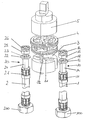
- the drawing shows the exploded view of an inventive Connection of the fitting of a pipeline for fluids.
- the drawing shows the fresh water supply lines 1, 2 for hot and cold water for connection to a sanitary mixer tap.
- the fresh water supply lines 1, 2 have at their lower end via known connection elements 100, 200 for Connection with fresh water pipes.
- connection elements 100, 200 for Connection with fresh water pipes.
- the upper connecting piece 10, 20 has at its end to be connected to an outwardly widened portion 12, 22.
- the outwardly widened portion 12, 22 of the connecting piece 10, 20 of the pipe or hose 1, 2 is annular in the illustrated embodiment.
- the outwardly widened section 12, 22 of the connecting piece 10, 20 of the pipe or hose 1, 2 in the recess 31, 32 of a connection adapter 3, wherein the recess 31, 32, the extended portion 12, 22 of the connecting piece 10, 20 engages under.
- the connection adapter 3 may be made in one piece as a corresponding connection plate for receiving the connecting pieces 10, 20 or also in several parts.
- Compound of the invention forms the top of the outwardly expanded Section 12, 22 of the fitting of the pipe or hose 1, 2 a annular step 13, 23, as a contact shoulder for a sealing ring 15, 25 or alternatively for an O-ring seal 16, 26 is used. After assembly will this O-ring seal 16, 26 from the bottom of the connecting plate 4 sealing pressed, wherein the connecting plate 4 in the illustrated embodiment of Connection to a mixing cartridge 5 is used.
- the connector 10, 20 has below the extended portion 12, 22nd a smaller diameter than the underlying tube or Hose line 1, 2 or as the clamp connection 11, 21, so that between the Pipe or hose 1, 2 or the press connection 11, 21 and after outer extended portion 12, 22 of the connector 10, 20 a Constriction 14, 24 exists.
- the constricted area 14, 24 of Connecting piece 10, 20 protrudes in the assembled state, a bore of the Connection adapter 3, wherein the bore of the connection adapter 3 in illustrated embodiment formed to a mouth-shaped receptacle is, wherein the width of the mouth receiving the diameter of the bore corresponding to the constricted portion 14, 24 of the connector 10, 20 receives.
- connection plate 3 only one Width corresponding to the diameter of the bore, forms the Recess 31, 32 of the connection plate 3 a contact shoulder, in which the after externally extended portion 12, 22 of the connector 10, 20 form fit rests and the contact shoulder of the connection adapter 3 a peripheral region of the fitting 10, 20 and the pipe or hose 1, 2 of more than 180 degrees.
- the compound according to the invention is against Secured sideways slipping.
- the extended portion 12, 22 of the connector 10, 20 a have any shape, so for example six- or octagonal shape be formed and eino in a correspondingly shaped recess.
- the assembly takes place by a lateral insertion of the to be connected Connecting piece 10, 20 of the pipe or hose 1, 2 in the mouth-shaped Recording the connection adapter 3 and inserting the extended section 12, 22 of the connecting piece 10, 20 in a recess 31, 32, the extended section 12, 22.
- Connection can be a single or multiple, especially up to four Compounds according to the invention be combined to form a structural unit.
- Connection adapter 3 may be different than in the illustrated embodiment a have other basic shape than a round basic shape, for example, an ellipsoidal or polygonal, wherein one or more compounds of the invention in Any arrangement can be created. It is also conceivable one rectangular basic shape of the connection adapter 3, in which several Compounds of the invention side by side on one side of the rectangle are arranged.
Abstract
Description
Die Erfindung betrifft eine formschlüssige Verbindung des Anschlussstücks einer Rohr- oder Schlauchleitung für Fluide, insbesondere einer Frischwasserzuleitung einer Sanitärmischarmatur.The invention relates to a positive connection of the connecting piece of a Pipe or hose line for fluids, in particular a fresh water supply line a sanitary mixer tap.
Zur Verbindung des Anschlussstücks einer Rohr- oder Schlauchleitung für Fluide, insbesondere einer Frischwasserzuleitung einer Sanitärmischarmatur, ist es üblich, das Anschlussstück einer solchen Rohr- oder Schlauchleitung mit einem Außengewinde zu versehen und das Anschlussstück in ein entsprechendes Innengewinde einzuschrauben. Zur Abdichtung wird üblicherweise eine O-Ring-Dichtung vorgesehen, welche hinter dem Außengewinde auf einem Absatz des Anschlussstückes der Rohr- oder Schlauchleitung anliegt. Nachteilig hierbei ist, dass erstens die O-Ring-Dichtung bis zu ihrem Sitz über das Gewinde geschoben werden muss und dabei beschädigt werden kann, dass zweitens die O-Ring-Dichtung in einem aufwendigen Montagevorgang über mehrere Gewindezüge hinweg zu ihrer Position zu führen ist und dass drittens die Rohr- oder Schlauchleitung mitsamt dem Anschlussstück in das entsprechend vorgesehene Innengewinde eingeschraubt werden muss.For connecting the fitting of a pipe or hose line for fluids, in particular, a fresh water supply to a sanitary mixer, it is customary, the fitting of such a pipe or hose with a To provide external thread and the connector in a corresponding Screw in internal thread. For sealing is usually an O-ring seal provided, which behind the external thread on a paragraph of the Connecting piece of the pipe or hose is applied. The disadvantage here is First, push the o-ring seal over its seat to its seat Secondly, the O-ring seal must be and damaged in a complex assembly process over several threads is to lead to their position and that third, the pipe or Hose line together with the connection piece in the accordingly provided Internal thread must be screwed.
Aufgabe der Erfindung ist es, eine formschlüssige Verbindung des Anschlussstücks einer Rohr- oder Schlauchleitung für Fluide, insbesondere einer Frischwasserzuleitung einer Sanitärmischarmatur zu schaffen, die es ermöglicht, den Montagevorgang sowohl hinsichtlich des Einbringens einer Dichtung, als auch hinsichtlich der Montage der gesamten Verbindung zu vereinfachen. The object of the invention is to provide a positive connection of the Connecting piece of a pipe or hose for fluids, in particular one Fresh water supply to create a sanitary mixer tap, which makes it possible the assembly process both in terms of the introduction of a seal, as well to simplify assembly of the entire connection.
Diese Aufgabe wird erfindungsgemäß dadurch gelöst, dass bei einer formschlüssigen Verbindung des Anschlussstücks einer Rohr- oder Schlauchleitung für Fluide mit einem Anschlussadapter, insbesondere einer Frischwasserzuleitung einer Sanitärmischarmatur, das obere Anschlussstück der Rohr- oder Schlauchleitung an seinem anzuschließenden Ende einen nach außen erweiterten Abschnitt aufweist, der in einer Ausnehmung des Anschlussadapters einliegt, die den erweiterten Abschnitt untergreift.This object is achieved in that at a positive connection of the fitting of a pipe or Hose line for fluids with a connection adapter, in particular one Fresh water supply of a sanitary mixer tap, the upper connector of Pipe or hose at its end to be connected to the outside extended portion which in a recess of the connection adapter that engages with the extended section.
Die Vorteile der erfindungsgemäßen formschlüssigen Verbindung sind die einfache und schnelle Montage, da lediglich ein seitliches Einschieben des anzuschließenden Endstückes der Rohr- oder Schlauchleitung und ein Einlegen in eine Ausnehmung erforderlich ist. Weitere Vorteile sind ein sicherer Halt sowie eine gute Abdichtung der erfindungsgemäßen Verbindung.The advantages of the positive connection according to the invention are the simple and quick installation, as only a lateral insertion of the to be connected end piece of the pipe or hose and an insert in a recess is required. Other benefits include a secure hold as well a good seal of the compound of the invention.
Die erfindungsgemäßen Verbindungsteile sind gegenüber Verbindungsteilen nach dem bekannten Stand der Technik einfacher und preiswerter herzustellen, da insbesondere die Fertigung eines Gewindes und eines Sechskantes zum Einschrauben entfällt.The connecting parts according to the invention are compared with connecting parts the prior art easier and cheaper to manufacture, since in particular the production of a thread and a hexagon for Screwing is eliminated.
Vorteilhafte Ausgestaltungen der Erfindung sind in den Unteransprüchen aufgeführt.Advantageous embodiments of the invention are in the subclaims listed.
Eine bevorzugte Ausführungsform der erfindungsgemäßen Verbindung ist in der Zeichnung dargestellt und wird im folgenden näher beschrieben.A preferred embodiment of the compound of the invention is in the Drawing shown and will be described in more detail below.
Die Zeichnung zeigt die Explosionsdarstellung einer erfindungsgemäßen Verbindung des Anschlussstücks einer Rohrleitung für Fluide.The drawing shows the exploded view of an inventive Connection of the fitting of a pipeline for fluids.
Die Zeichnung zeigt die Frischwasserzuleitungen 1, 2 für Warm- und Kaltwasser
zum Anschluss an eine Sanitärmischarmatur. Die Frischwasserzuleitungen 1, 2
verfügen an ihrem unteren Ende über bekannte Anschlusselemente 100, 200 zur
Verbindung mit Frischwasserleitungen. An ihrem oberen Ende, welches an die
Sanitärmischarmatur anzuschließen ist, verfügen die Rohr- oder
Schlauchleitungen 1, 2 über Anschlussstücke 10, 20, die mittels bekannter
Pressverbindungen 11, 21 mit den Rohr- oder Schlauchleitungen 1, 2 verbunden
ist.The drawing shows the fresh
Das obere Anschlussstück 10, 20 weist an seinem anzuschließenden Ende einen
nach außen erweiterten Abschnitt 12, 22 auf. Der nach außen erweiterte Abschnitt
12, 22 des Anschlussstücks 10, 20 der Rohr- oder Schlauchleitung 1, 2 ist in dem
dargestellten Ausführungsbeispiel ringförmig ausgebildet. Nach der Montage der
erfindungsgemäßen Verbindung liegt der nach außen erweiterte Abschnitt 12, 22
des Anschlussstücks 10, 20 der Rohr- oder Schlauchleitung 1, 2 in der
Ausnehmung 31, 32 eines Anschlussadapters 3 ein, wobei die Ausnehmung 31,
32 den erweiterten Abschnitt 12, 22 des Anschlussstücks 10, 20 untergreift.
Der Anschlussadapter 3 kann einstückig als entsprechende Anschlussplatte zur
Aufnahme der Anschlussstücke 10, 20 oder auch mehrteilig ausgeführt sein.The upper connecting
The
Bei dem in der Zeichnung dargestellten Ausführungsbeispiel der
erfindungsgemäßen Verbindung bildet die Oberseite des nach außen erweiterten
Abschnitts 12, 22 des Anschlussstücks der Rohr- oder Schlauchleitung 1, 2 eine
ringförmige Stufe 13, 23, die als Anlageschulter für einen Dichtring 15, 25 oder
alternativ für eine O-Ring-Dichtung 16, 26 dient. Nach dem Zusammenbau wird
diese O-Ring-Dichtung 16, 26 von der Unterseite der Verbindungsplatte 4 dichtend
verpresst, wobei die Verbindungsplatte 4 im dargestellten Ausführungsbeispiel der
Verbindung zu einer Mischkartusche 5 dient.In the embodiment of the illustrated in the drawing
Compound of the invention forms the top of the outwardly expanded
Das Anschlussstück 10, 20 weist unterhalb des erweiterten Abschnitts 12, 22
einen geringeren Durchmesser auf als die darunter liegende Rohr- oder
Schlauchleitung 1, 2 bzw. als die Klemmverbindung 11, 21, so dass zwischen der
Rohr- oder Schlauchleitung 1, 2 bzw. der Pressverbindung 11, 21 und dem nach
außen erweiterten Abschnitt 12, 22 des Anschlussstücks 10, 20 eine
Einschnürung 14, 24 besteht. Der eingeschnürte Bereich 14, 24 des
Anschlussstücks 10, 20 durchragt im montierten Zustand eine Bohrung des
Anschlussadapters 3, wobei die Bohrung des Anschlussadapters 3 im
dargestellten Ausführungsbeispiel zu einer maulförmigen Aufnahme ausgebildet
ist, wobei die Breite der maulförmigen Aufnahme dem Durchmesser der Bohrung
entspricht, die den eingeschnürten Bereich 14, 24 des Anschlussstücks 10, 20
aufnimmt.The
Dadurch dass die maulförmige Aufnahme der Anschlussplatte 3 lediglich eine
Breite entsprechend dem Durchmesser der Bohrung aufweist, bildet die
Ausnehmung 31, 32 der Anschlussplatte 3 eine Anlageschulter, in der der nach
außen erweiterte Abschnitt 12, 22 des Anschlussstücks 10, 20 formschlüssig
einliegt und die Anlageschulter des Anschlussadapters 3 einen Umfangsbereich
des Anschlussstücks 10, 20 und der Rohr- oder Schlauchleitung 1, 2 von mehr als
180 Grad umfasst. Dadurch ist die erfindungsgemäße Verbindung gegen ein
seitliches Herausrutschen gesichert.The fact that the mouth-shaped receptacle of the
Alternativ zum dargestellten Ausführungsbeispiel der erfindungsgemäßen
Verbindung kann der erweiterte Abschnitt 12, 22 des Anschlussstücks 10, 20 eine
beliebige Form aufweisen, also beispielsweise sechs- oder achteckförmig
ausgebildet sein und in einer entsprechend ausgeformten Ausnehmung einliegen.Alternatively to the illustrated embodiment of the invention
Connection, the
Die Montage erfolgt durch ein seitliches Einschieben des anzuschließenden
Anschlussstückes 10, 20 der Rohr- oder Schlauchleitung 1, 2 in die maulförmige
Aufnahme des Anschlussadapters 3 und ein Einlegen des erweiterten Abschnitts
12, 22 des Anschlussstückes 10 ,20 in eine Ausnehmung 31, 32, die den
erweiterten Abschnitt 12, 22 untergreift.The assembly takes place by a lateral insertion of the to be connected
Connecting
Alternativ zum dargestellten Ausführungsbeispiel der erfindungsgemäßen
Verbindung kann eine einzelne oder mehrere, insbesondere bis zu vier
erfindungsgemäße Verbindungen zu einer Baueinheit zusammengefasst sein. Der
Anschlussadapter 3 kann anders als im dargestellten Ausführungsbeispiel eine
andere Grundform als eine runde Grundform haben, beipsielsweise eine ellipsoide
oder mehreckige, wobei eine oder mehrere erfindungsgemäße Verbindungen in
beliebiger Anordnung geschaffen werden können. Denkbar ist auch eine
rechteckige Grundform des Anschlussadapters 3, bei dem mehrere
erfindungsgemäße Verbindungen nebeneinander an einer Seite des Rechtecks
angeordnet sind.Alternatively to the illustrated embodiment of the invention
Connection can be a single or multiple, especially up to four
Compounds according to the invention be combined to form a structural unit. Of the
Claims (9)
Applications Claiming Priority (2)
| Application Number | Priority Date | Filing Date | Title |
|---|---|---|---|
| DE10330685A DE10330685A1 (en) | 2003-07-08 | 2003-07-08 | Positive connection of the fitting of a pipeline |
| DE10330685 | 2003-07-08 |
Publications (2)
| Publication Number | Publication Date |
|---|---|
| EP1496164A1 true EP1496164A1 (en) | 2005-01-12 |
| EP1496164B1 EP1496164B1 (en) | 2005-12-14 |
Family
ID=33441644
Family Applications (1)
| Application Number | Title | Priority Date | Filing Date |
|---|---|---|---|
| EP03023338A Expired - Lifetime EP1496164B1 (en) | 2003-07-08 | 2003-10-15 | Positive connection of the fitting of a conduit |
Country Status (4)
| Country | Link |
|---|---|
| EP (1) | EP1496164B1 (en) |
| AT (1) | ATE312979T1 (en) |
| DE (2) | DE10330685A1 (en) |
| ES (1) | ES2250809T3 (en) |
Cited By (4)
| Publication number | Priority date | Publication date | Assignee | Title |
|---|---|---|---|---|
| GB2416824A (en) * | 2004-08-04 | 2006-02-08 | Peter Roland Bradley | Tap mounting means |
| WO2007076861A1 (en) * | 2006-01-03 | 2007-07-12 | Broen A/S | Connection arrangement between a fitting unit and a medium pipe |
| WO2008120252A1 (en) * | 2007-03-30 | 2008-10-09 | Crs S.P.A. | Tap |
| WO2021105302A1 (en) * | 2019-11-29 | 2021-06-03 | Neoperl Gmbh | Sanitary fitting |
Families Citing this family (4)
| Publication number | Priority date | Publication date | Assignee | Title |
|---|---|---|---|---|
| DE102006053590A1 (en) * | 2006-11-02 | 2008-05-08 | Kludi Gmbh & Co. Kg | Hose mounting unit for use in armature e.g. sanitary armature, has loading area extending over insertion channels up to receiving position for nipple of hose, where channels are designed together in angle and flow in common loading area |
| PL2220297T3 (en) * | 2007-11-19 | 2012-01-31 | Kludi Gmbh & Co Kg | Hose fastening element for a sanitary or kitchen fitting |
| DE102020107281A1 (en) | 2020-03-17 | 2021-09-23 | Grohe Ag | Sanitary fitting with at least one feed line secured by a base shaft |
| DE202020104394U1 (en) | 2020-07-29 | 2021-11-02 | Neoperl Gmbh | Sanitary interface, sanitary fitting, construction kit for producing a sanitary interface and using a sanitary interface |
Citations (6)
| Publication number | Priority date | Publication date | Assignee | Title |
|---|---|---|---|---|
| DE3119313A1 (en) * | 1981-05-15 | 1982-12-02 | Hansa Metallwerke Ag, 7000 Stuttgart | Sanitary fitting |
| US4667987A (en) * | 1985-01-19 | 1987-05-26 | Knebel & Rottger Gmbh & Co. | Device for connecting pipes with fittings |
| US5294156A (en) * | 1991-02-20 | 1994-03-15 | Nippondenso Co., Ltd. | Flange coupling for connecting pipes for carrying refrigerant during refrigerating cycle |
| US5558128A (en) * | 1994-05-05 | 1996-09-24 | Friedrich Grohe Aktiengesellschaft | One-hole mount mixing faucet |
| WO1997017501A1 (en) * | 1995-11-09 | 1997-05-15 | Ideal-Standard Gmbh | Sanitary tap |
| EP1022500A2 (en) * | 1999-01-22 | 2000-07-26 | Hansa Metallwerke Ag | Sanitary valve, especially for wash basins |
Family Cites Families (2)
| Publication number | Priority date | Publication date | Assignee | Title |
|---|---|---|---|---|
| DE3141475C2 (en) * | 1981-10-20 | 1986-10-02 | Gewerkschaft Eisenhütte Westfalia, 4670 Lünen | Hose coupling for multi-core hydraulic cables for use in hydraulic support systems in mining operations |
| EP0713994B1 (en) * | 1994-11-23 | 2000-09-20 | Automotive Fluid Systems, Inc. | Connecting block with inserts |
-
2003
- 2003-07-08 DE DE10330685A patent/DE10330685A1/en not_active Withdrawn
- 2003-10-15 DE DE50301932T patent/DE50301932D1/en not_active Expired - Lifetime
- 2003-10-15 EP EP03023338A patent/EP1496164B1/en not_active Expired - Lifetime
- 2003-10-15 AT AT03023338T patent/ATE312979T1/en active
- 2003-10-15 ES ES03023338T patent/ES2250809T3/en not_active Expired - Lifetime
Patent Citations (6)
| Publication number | Priority date | Publication date | Assignee | Title |
|---|---|---|---|---|
| DE3119313A1 (en) * | 1981-05-15 | 1982-12-02 | Hansa Metallwerke Ag, 7000 Stuttgart | Sanitary fitting |
| US4667987A (en) * | 1985-01-19 | 1987-05-26 | Knebel & Rottger Gmbh & Co. | Device for connecting pipes with fittings |
| US5294156A (en) * | 1991-02-20 | 1994-03-15 | Nippondenso Co., Ltd. | Flange coupling for connecting pipes for carrying refrigerant during refrigerating cycle |
| US5558128A (en) * | 1994-05-05 | 1996-09-24 | Friedrich Grohe Aktiengesellschaft | One-hole mount mixing faucet |
| WO1997017501A1 (en) * | 1995-11-09 | 1997-05-15 | Ideal-Standard Gmbh | Sanitary tap |
| EP1022500A2 (en) * | 1999-01-22 | 2000-07-26 | Hansa Metallwerke Ag | Sanitary valve, especially for wash basins |
Cited By (7)
| Publication number | Priority date | Publication date | Assignee | Title |
|---|---|---|---|---|
| GB2416824A (en) * | 2004-08-04 | 2006-02-08 | Peter Roland Bradley | Tap mounting means |
| WO2007076861A1 (en) * | 2006-01-03 | 2007-07-12 | Broen A/S | Connection arrangement between a fitting unit and a medium pipe |
| US9637894B2 (en) | 2006-01-03 | 2017-05-02 | Broen-Lab A/S | Connection arrangement between a fitting unit and a medium pipe |
| EP1969190B1 (en) | 2006-01-03 | 2019-02-20 | Broen-Lab A/S | Connection arrangement between a fitting unit and a medium pipe |
| WO2008120252A1 (en) * | 2007-03-30 | 2008-10-09 | Crs S.P.A. | Tap |
| WO2021105302A1 (en) * | 2019-11-29 | 2021-06-03 | Neoperl Gmbh | Sanitary fitting |
| CN114761644A (en) * | 2019-11-29 | 2022-07-15 | 纽珀有限公司 | Sanitary fitting |
Also Published As
| Publication number | Publication date |
|---|---|
| ATE312979T1 (en) | 2005-12-15 |
| EP1496164B1 (en) | 2005-12-14 |
| DE10330685A1 (en) | 2005-02-03 |
| ES2250809T3 (en) | 2006-04-16 |
| DE50301932D1 (en) | 2006-01-19 |
Similar Documents
| Publication | Publication Date | Title |
|---|---|---|
| DE202014006320U1 (en) | Connection device and sanitary facility | |
| EP2857733B1 (en) | Combination comprising a hose connector, a hose nipple and a nut | |
| EP1496164B1 (en) | Positive connection of the fitting of a conduit | |
| EP0261326B1 (en) | Corner valve for building water mains | |
| EP0876564A1 (en) | Pipe connecting device | |
| EP1484544B1 (en) | Conduit feed-through for the installation of a sanitary tube through a wall | |
| EP2586934A1 (en) | Sprinkler connection box | |
| EP2251495B1 (en) | Water connection assembly with a connection piece for simplified fitting of a connection device, in particular a water treatment device | |
| DE3707705A1 (en) | Discharge fitting | |
| EP1457727B1 (en) | Connection of a sanitary fitting with a conduit | |
| DE3325350C2 (en) | ||
| DE3221518C2 (en) | Fittings for the automatic connection of lines in pneumatic or hydraulic circuits | |
| EP3683367B1 (en) | Washbasin installation assembly and method of assembling a washbasin installation assembly | |
| DE102004037051A1 (en) | Mixer tap for sanitary fittings has an inner adapters which can be set in different positions and which have upstream stream tails for connecting to the supply pipes | |
| DE10233863A1 (en) | Connecting block for sanitary fittings comprises connector for hot and cold water pipe of interior installation, connector for pipe leading to consumer and rinsing block connected to the connecting block in place of the sanitary fitting | |
| DE102017123765A1 (en) | Adapter for connecting a valve or flush valve to a pipeline and system with such an adapter and a pretext frame element | |
| DE202006009648U1 (en) | Distributor fitting for house water installation, has connecting pipe whose plug end is stuck into or on outlet connection, and coupling, sealing, clamping, pressing and cone rings provided for fixing pipe at outlet connection | |
| DE102005006708A1 (en) | Water meter e.g. domestic water meter, housing, has inlet and outlet connections for water-proof, removable installation in suitable end pieces of water pipes, where one connection is formed outside as sleek cylinder | |
| DE4039663A1 (en) | Water pipe fitment stopper - has main part with valve inside in seating, with compression spring and guide piece | |
| DE2412679A1 (en) | Wall connection for water fitting - has polyamide baseplate and can be connected in differing positions | |
| EP0336397A1 (en) | Coupling device for water meters | |
| DE3346081A1 (en) | Mixer unit with upright connection | |
| DE10302358A1 (en) | Leak-proof connection sleeve for pipes of different outside diameters with smooth ends | |
| DE4007278A1 (en) | Connecting fixture for single branch gas meter - has connecting piece with short feed pipes for meter, consumer and stop cock and is accommodated in building service box | |
| DE4125570A1 (en) | Connection of pipe to water tap - involves screwed bush with groove to receive turned over edge of pipe |
Legal Events
| Date | Code | Title | Description |
|---|---|---|---|
| PUAI | Public reference made under article 153(3) epc to a published international application that has entered the european phase |
Free format text: ORIGINAL CODE: 0009012 |
|
| AK | Designated contracting states |
Kind code of ref document: A1 Designated state(s): AT BE BG CH CY CZ DE DK EE ES FI FR GB GR HU IE IT LI LU MC NL PT RO SE SI SK TR |
|
| AX | Request for extension of the european patent |
Extension state: AL LT LV MK |
|
| 17P | Request for examination filed |
Effective date: 20050201 |
|
| GRAP | Despatch of communication of intention to grant a patent |
Free format text: ORIGINAL CODE: EPIDOSNIGR1 |
|
| GRAS | Grant fee paid |
Free format text: ORIGINAL CODE: EPIDOSNIGR3 |
|
| AKX | Designation fees paid |
Designated state(s): AT BE BG CH CY CZ DE DK EE ES FI FR GB GR HU IE IT LI LU MC NL PT RO SE SI SK TR |
|
| GRAA | (expected) grant |
Free format text: ORIGINAL CODE: 0009210 |
|
| AK | Designated contracting states |
Kind code of ref document: B1 Designated state(s): AT BE BG CH CY CZ DE DK EE ES FI FR GB GR HU IE IT LI LU MC NL PT RO SE SI SK TR |
|
| PG25 | Lapsed in a contracting state [announced via postgrant information from national office to epo] |
Ref country code: FI Free format text: LAPSE BECAUSE OF FAILURE TO SUBMIT A TRANSLATION OF THE DESCRIPTION OR TO PAY THE FEE WITHIN THE PRESCRIBED TIME-LIMIT Effective date: 20051214 Ref country code: IT Free format text: LAPSE BECAUSE OF FAILURE TO SUBMIT A TRANSLATION OF THE DESCRIPTION OR TO PAY THE FEE WITHIN THE PRESCRIBED TIME-LIMIT;WARNING: LAPSES OF ITALIAN PATENTS WITH EFFECTIVE DATE BEFORE 2007 MAY HAVE OCCURRED AT ANY TIME BEFORE 2007. THE CORRECT EFFECTIVE DATE MAY BE DIFFERENT FROM THE ONE RECORDED. Effective date: 20051214 Ref country code: NL Free format text: LAPSE BECAUSE OF FAILURE TO SUBMIT A TRANSLATION OF THE DESCRIPTION OR TO PAY THE FEE WITHIN THE PRESCRIBED TIME-LIMIT Effective date: 20051214 Ref country code: CZ Free format text: LAPSE BECAUSE OF FAILURE TO SUBMIT A TRANSLATION OF THE DESCRIPTION OR TO PAY THE FEE WITHIN THE PRESCRIBED TIME-LIMIT Effective date: 20051214 Ref country code: RO Free format text: LAPSE BECAUSE OF FAILURE TO SUBMIT A TRANSLATION OF THE DESCRIPTION OR TO PAY THE FEE WITHIN THE PRESCRIBED TIME-LIMIT Effective date: 20051214 Ref country code: IE Free format text: LAPSE BECAUSE OF FAILURE TO SUBMIT A TRANSLATION OF THE DESCRIPTION OR TO PAY THE FEE WITHIN THE PRESCRIBED TIME-LIMIT Effective date: 20051214 Ref country code: SK Free format text: LAPSE BECAUSE OF FAILURE TO SUBMIT A TRANSLATION OF THE DESCRIPTION OR TO PAY THE FEE WITHIN THE PRESCRIBED TIME-LIMIT Effective date: 20051214 Ref country code: SI Free format text: LAPSE BECAUSE OF FAILURE TO SUBMIT A TRANSLATION OF THE DESCRIPTION OR TO PAY THE FEE WITHIN THE PRESCRIBED TIME-LIMIT Effective date: 20051214 |
|
| REG | Reference to a national code |
Ref country code: GB Ref legal event code: FG4D Free format text: NOT ENGLISH |
|
| REG | Reference to a national code |
Ref country code: CH Ref legal event code: EP |
|
| REG | Reference to a national code |
Ref country code: IE Ref legal event code: FG4D Free format text: LANGUAGE OF EP DOCUMENT: GERMAN |
|
| REF | Corresponds to: |
Ref document number: 50301932 Country of ref document: DE Date of ref document: 20060119 Kind code of ref document: P |
|
| PG25 | Lapsed in a contracting state [announced via postgrant information from national office to epo] |
Ref country code: BG Free format text: LAPSE BECAUSE OF FAILURE TO SUBMIT A TRANSLATION OF THE DESCRIPTION OR TO PAY THE FEE WITHIN THE PRESCRIBED TIME-LIMIT Effective date: 20060314 Ref country code: DK Free format text: LAPSE BECAUSE OF FAILURE TO SUBMIT A TRANSLATION OF THE DESCRIPTION OR TO PAY THE FEE WITHIN THE PRESCRIBED TIME-LIMIT Effective date: 20060314 Ref country code: SE Free format text: LAPSE BECAUSE OF FAILURE TO SUBMIT A TRANSLATION OF THE DESCRIPTION OR TO PAY THE FEE WITHIN THE PRESCRIBED TIME-LIMIT Effective date: 20060314 Ref country code: GR Free format text: LAPSE BECAUSE OF FAILURE TO SUBMIT A TRANSLATION OF THE DESCRIPTION OR TO PAY THE FEE WITHIN THE PRESCRIBED TIME-LIMIT Effective date: 20060314 |
|
| GBT | Gb: translation of ep patent filed (gb section 77(6)(a)/1977) |
Effective date: 20060216 |
|
| REG | Reference to a national code |
Ref country code: HU Ref legal event code: AG4A Ref document number: E000177 Country of ref document: HU |
|
| REG | Reference to a national code |
Ref country code: ES Ref legal event code: FG2A Ref document number: 2250809 Country of ref document: ES Kind code of ref document: T3 |
|
| PG25 | Lapsed in a contracting state [announced via postgrant information from national office to epo] |
Ref country code: PT Free format text: LAPSE BECAUSE OF FAILURE TO SUBMIT A TRANSLATION OF THE DESCRIPTION OR TO PAY THE FEE WITHIN THE PRESCRIBED TIME-LIMIT Effective date: 20060515 |
|
| NLV1 | Nl: lapsed or annulled due to failure to fulfill the requirements of art. 29p and 29m of the patents act | ||
| REG | Reference to a national code |
Ref country code: IE Ref legal event code: FD4D |
|
| ET | Fr: translation filed | ||
| PLBE | No opposition filed within time limit |
Free format text: ORIGINAL CODE: 0009261 |
|
| STAA | Information on the status of an ep patent application or granted ep patent |
Free format text: STATUS: NO OPPOSITION FILED WITHIN TIME LIMIT |
|
| PG25 | Lapsed in a contracting state [announced via postgrant information from national office to epo] |
Ref country code: MC Free format text: LAPSE BECAUSE OF NON-PAYMENT OF DUE FEES Effective date: 20061031 |
|
| 26N | No opposition filed |
Effective date: 20060915 |
|
| BERE | Be: lapsed |
Owner name: KLUDI G.M.B.H. & CO. KG Effective date: 20061031 |
|
| REG | Reference to a national code |
Ref country code: CH Ref legal event code: PL |
|
| PG25 | Lapsed in a contracting state [announced via postgrant information from national office to epo] |
Ref country code: EE Free format text: LAPSE BECAUSE OF FAILURE TO SUBMIT A TRANSLATION OF THE DESCRIPTION OR TO PAY THE FEE WITHIN THE PRESCRIBED TIME-LIMIT Effective date: 20051214 |
|
| PG25 | Lapsed in a contracting state [announced via postgrant information from national office to epo] |
Ref country code: LI Free format text: LAPSE BECAUSE OF NON-PAYMENT OF DUE FEES Effective date: 20071031 Ref country code: TR Free format text: LAPSE BECAUSE OF FAILURE TO SUBMIT A TRANSLATION OF THE DESCRIPTION OR TO PAY THE FEE WITHIN THE PRESCRIBED TIME-LIMIT Effective date: 20051214 Ref country code: LU Free format text: LAPSE BECAUSE OF NON-PAYMENT OF DUE FEES Effective date: 20061015 Ref country code: CH Free format text: LAPSE BECAUSE OF NON-PAYMENT OF DUE FEES Effective date: 20071031 |
|
| PG25 | Lapsed in a contracting state [announced via postgrant information from national office to epo] |
Ref country code: CY Free format text: LAPSE BECAUSE OF FAILURE TO SUBMIT A TRANSLATION OF THE DESCRIPTION OR TO PAY THE FEE WITHIN THE PRESCRIBED TIME-LIMIT Effective date: 20051214 |
|
| PG25 | Lapsed in a contracting state [announced via postgrant information from national office to epo] |
Ref country code: BE Free format text: LAPSE BECAUSE OF FAILURE TO SUBMIT A TRANSLATION OF THE DESCRIPTION OR TO PAY THE FEE WITHIN THE PRESCRIBED TIME-LIMIT Effective date: 20061031 |
|
| PGFP | Annual fee paid to national office [announced via postgrant information from national office to epo] |
Ref country code: IT Payment date: 20101025 Year of fee payment: 8 |
|
| PGFP | Annual fee paid to national office [announced via postgrant information from national office to epo] |
Ref country code: FR Payment date: 20111103 Year of fee payment: 9 Ref country code: ES Payment date: 20111021 Year of fee payment: 9 |
|
| PGFP | Annual fee paid to national office [announced via postgrant information from national office to epo] |
Ref country code: GB Payment date: 20121030 Year of fee payment: 10 |
|
| REG | Reference to a national code |
Ref country code: FR Ref legal event code: ST Effective date: 20130628 |
|
| PG25 | Lapsed in a contracting state [announced via postgrant information from national office to epo] |
Ref country code: IT Free format text: LAPSE BECAUSE OF NON-PAYMENT OF DUE FEES Effective date: 20121015 Ref country code: FR Free format text: LAPSE BECAUSE OF NON-PAYMENT OF DUE FEES Effective date: 20121031 |
|
| REG | Reference to a national code |
Ref country code: ES Ref legal event code: FD2A Effective date: 20140116 |
|
| PG25 | Lapsed in a contracting state [announced via postgrant information from national office to epo] |
Ref country code: ES Free format text: LAPSE BECAUSE OF NON-PAYMENT OF DUE FEES Effective date: 20121016 |
|
| GBPC | Gb: european patent ceased through non-payment of renewal fee |
Effective date: 20131015 |
|
| PG25 | Lapsed in a contracting state [announced via postgrant information from national office to epo] |
Ref country code: GB Free format text: LAPSE BECAUSE OF NON-PAYMENT OF DUE FEES Effective date: 20131015 |
|
| PGFP | Annual fee paid to national office [announced via postgrant information from national office to epo] |
Ref country code: DE Payment date: 20141022 Year of fee payment: 12 |
|
| PGFP | Annual fee paid to national office [announced via postgrant information from national office to epo] |
Ref country code: AT Payment date: 20141022 Year of fee payment: 12 Ref country code: HU Payment date: 20141021 Year of fee payment: 12 |
|
| REG | Reference to a national code |
Ref country code: DE Ref legal event code: R082 Ref document number: 50301932 Country of ref document: DE Representative=s name: TARVENKORN & WICKORD PATENTANWAELTE PARTG MBB, DE |
|
| REG | Reference to a national code |
Ref country code: DE Ref legal event code: R119 Ref document number: 50301932 Country of ref document: DE |
|
| REG | Reference to a national code |
Ref country code: AT Ref legal event code: MM01 Ref document number: 312979 Country of ref document: AT Kind code of ref document: T Effective date: 20151015 |
|
| PG25 | Lapsed in a contracting state [announced via postgrant information from national office to epo] |
Ref country code: DE Free format text: LAPSE BECAUSE OF NON-PAYMENT OF DUE FEES Effective date: 20160503 |
|
| PG25 | Lapsed in a contracting state [announced via postgrant information from national office to epo] |
Ref country code: HU Free format text: LAPSE BECAUSE OF NON-PAYMENT OF DUE FEES Effective date: 20151016 Ref country code: AT Free format text: LAPSE BECAUSE OF NON-PAYMENT OF DUE FEES Effective date: 20151015 |