EP1495998A1 - Vorrichtung zum Entpalettieren eines Bobinenstapels mit einem Laserentfernungssensor und Verwendung eines Laserentfernungssensors zur Entpalettierung eines Bobinenstapels - Google Patents
Vorrichtung zum Entpalettieren eines Bobinenstapels mit einem Laserentfernungssensor und Verwendung eines Laserentfernungssensors zur Entpalettierung eines Bobinenstapels Download PDFInfo
- Publication number
- EP1495998A1 EP1495998A1 EP03015827A EP03015827A EP1495998A1 EP 1495998 A1 EP1495998 A1 EP 1495998A1 EP 03015827 A EP03015827 A EP 03015827A EP 03015827 A EP03015827 A EP 03015827A EP 1495998 A1 EP1495998 A1 EP 1495998A1
- Authority
- EP
- European Patent Office
- Prior art keywords
- laser
- gripper
- bobbins
- bobbin
- sensor
- Prior art date
- Legal status (The legal status is an assumption and is not a legal conclusion. Google has not performed a legal analysis and makes no representation as to the accuracy of the status listed.)
- Withdrawn
Links
- 238000005259 measurement Methods 0.000 claims description 8
- 238000012545 processing Methods 0.000 claims description 4
- 238000004519 manufacturing process Methods 0.000 description 5
- 230000004888 barrier function Effects 0.000 description 3
- 239000000463 material Substances 0.000 description 3
- 238000000034 method Methods 0.000 description 3
- 230000007704 transition Effects 0.000 description 3
- 238000013459 approach Methods 0.000 description 2
- 238000001514 detection method Methods 0.000 description 2
- 230000033001 locomotion Effects 0.000 description 2
- 238000004806 packaging method and process Methods 0.000 description 2
- 239000000523 sample Substances 0.000 description 2
- 208000036829 Device dislocation Diseases 0.000 description 1
- 241000208125 Nicotiana Species 0.000 description 1
- 235000002637 Nicotiana tabacum Nutrition 0.000 description 1
- 230000001133 acceleration Effects 0.000 description 1
- 230000003213 activating effect Effects 0.000 description 1
- WYTGDNHDOZPMIW-RCBQFDQVSA-N alstonine Natural products C1=CC2=C3C=CC=CC3=NC2=C2N1C[C@H]1[C@H](C)OC=C(C(=O)OC)[C@H]1C2 WYTGDNHDOZPMIW-RCBQFDQVSA-N 0.000 description 1
- XAGFODPZIPBFFR-UHFFFAOYSA-N aluminium Chemical compound [Al] XAGFODPZIPBFFR-UHFFFAOYSA-N 0.000 description 1
- 229910052782 aluminium Inorganic materials 0.000 description 1
- 230000009286 beneficial effect Effects 0.000 description 1
- 239000000969 carrier Substances 0.000 description 1
- 235000019504 cigarettes Nutrition 0.000 description 1
- 238000013461 design Methods 0.000 description 1
- 238000010586 diagram Methods 0.000 description 1
- 239000011888 foil Substances 0.000 description 1
- 239000005022 packaging material Substances 0.000 description 1
- 239000002985 plastic film Substances 0.000 description 1
- 229920006255 plastic film Polymers 0.000 description 1
- 238000005070 sampling Methods 0.000 description 1
- 230000029305 taxis Effects 0.000 description 1
- 238000012360 testing method Methods 0.000 description 1
Images



Classifications
-
- B—PERFORMING OPERATIONS; TRANSPORTING
- B65—CONVEYING; PACKING; STORING; HANDLING THIN OR FILAMENTARY MATERIAL
- B65G—TRANSPORT OR STORAGE DEVICES, e.g. CONVEYORS FOR LOADING OR TIPPING, SHOP CONVEYOR SYSTEMS OR PNEUMATIC TUBE CONVEYORS
- B65G47/00—Article or material-handling devices associated with conveyors; Methods employing such devices
- B65G47/74—Feeding, transfer, or discharging devices of particular kinds or types
- B65G47/90—Devices for picking-up and depositing articles or materials
- B65G47/905—Control arrangements
-
- B—PERFORMING OPERATIONS; TRANSPORTING
- B65—CONVEYING; PACKING; STORING; HANDLING THIN OR FILAMENTARY MATERIAL
- B65G—TRANSPORT OR STORAGE DEVICES, e.g. CONVEYORS FOR LOADING OR TIPPING, SHOP CONVEYOR SYSTEMS OR PNEUMATIC TUBE CONVEYORS
- B65G61/00—Use of pick-up or transfer devices or of manipulators for stacking or de-stacking articles not otherwise provided for
-
- B—PERFORMING OPERATIONS; TRANSPORTING
- B65—CONVEYING; PACKING; STORING; HANDLING THIN OR FILAMENTARY MATERIAL
- B65H—HANDLING THIN OR FILAMENTARY MATERIAL, e.g. SHEETS, WEBS, CABLES
- B65H19/00—Changing the web roll
- B65H19/10—Changing the web roll in unwinding mechanisms or in connection with unwinding operations
- B65H19/12—Lifting, transporting, or inserting the web roll; Removing empty core
-
- B—PERFORMING OPERATIONS; TRANSPORTING
- B65—CONVEYING; PACKING; STORING; HANDLING THIN OR FILAMENTARY MATERIAL
- B65H—HANDLING THIN OR FILAMENTARY MATERIAL, e.g. SHEETS, WEBS, CABLES
- B65H67/00—Replacing or removing cores, receptacles, or completed packages at paying-out, winding, or depositing stations
- B65H67/06—Supplying cores, receptacles, or packages to, or transporting from, winding or depositing stations
- B65H67/064—Supplying or transporting cross-wound packages, also combined with transporting the empty core
Definitions
- the invention relates to a device for depalletizing a bobbin stack by means of a gripper and a use of a Laser range sensor.
- packaging material such as. Paper, aluminum foil, plastic film or laminated film
- processed by rolls also known as reels
- These bobbins become a unwinding device brought and postponed to this.
- tobacco processing Machines e.g. Cigarette making machines become reels needed with paper.
- DE-A-35 01 692 discloses a device for unloading individual bobbins disclosed by a pad or pallet.
- a Gripping device moved via linear drives in a plane that is arranged on a height-adjustable frame.
- Sensors are attached, which are the position of lying in a plane Capture bobbins and the height adjustment of the frame Taxes.
- the sensors can each be a bobbin row be assigned on a palette.
- the solution of the problem takes place in a device for depalletizing a stack of bobbins by means of a gripper in that at least one laser distance sensor for measuring the height of the Bobbins stack is provided.
- a device according to DE-A-35 01 692 (corresponds to US-4,723,884), the fully in the The present application is incorporated into Bobinen from a base i. Pallet on which the bobbins in several Rows next to each other and stacked in several layers are discharged by means of a gripper.
- the gripper detects specifically the individual bobbins and leads them either directly to a take-off device a downstream packaging machine or a transport system that the bobbins to a unwinding device or a buffer magazine arranged on the unwinding device transported.
- the laser distance sensor By means of the laser distance sensor according to the invention is the Distance between the uppermost layer of bobbins and the gripper Measured in a simple and fast way.
- the laser distance sensor sends a laser beam coming from the distant one Measuring object (Bobine) is reflected.
- These laser distance sensors convert the determined distance into a proportional electric Signal around.
- This targeted selective distance measurement is Ensures that a gripper quickly reaches a bobbin to be gripped and in general one compared to an ultrasonic sensor measurement, which has a measuring lobe, whereby an accurate and targeted measurement is limited and very small areas can not be detected, accelerated distance measurement is possible. As a result, the production speed of a device significantly increased.
- the laser distance sensor for determining the Distance between the bobbin stack and the gripper provided.
- each bobbin row of the bobbin stack is a laser range sensor assigned.
- the laser distance sensors In particular on a cross member, arranged side by side. This will result in simultaneous and parallel detection the distances guaranteed with only one crossing of the bobbin stack.
- the laser removal sensor on the gripper is arranged so that a compact design of the gripper is possible.
- the device is designed as a gantry robot.
- a gantry robot consists of a portal that is divided into two Can move rails in the longitudinal direction (x-axis).
- the portal is a trolley mounted, which is transverse to the direction of movement of the portal can move (y-axis).
- a gripper arm is mounted, which moves up and down (z-axis).
- a gripping device is arranged.
- Such portal robots have opted for depalletizing proven by Bobinenpaletten.
- the sensors are in at least one or all spatial directions movable.
- Another object of the invention is the use of a laser range sensor proposed in a device for depalletizing a Bobinenstapel provided by means of a gripper is, wherein the laser range sensor for distance measurement is provided between the bobbin stack and the gripper. Of the Laser removal sensor scans the topmost position of the bobbins from.
- FIGS. 1 and 2 schematically show the sequence of scanning of Pallets 20, 25 with bobbins 30, 35 as well as the determination of the bobbin center represented according to the prior art. in this connection are the reels 30, 35 on the pallets 20, 25 in rows next to each other and arranged in layers one above the other.
- the loading height of the pallets used as a base 20, 25 is in accordance with the prior art with an ultrasonic sensor determined by meandering descending the individual pallets 20, 25.
- the ultrasonic sensor is combined with a Gripping head of the robot, in particular gantry robot, from a Parking position A out in direction B. From point B is the ultrasonic sensor proceed via points C, D, E, F to G. in this connection The changes in stack height are stored in a controller. Thereafter, the ultrasonic sensor moves back from point G. in parking position A.
- the ultrasonic sensor moves out of the parking position A to point H on the pallet 25 and feels the pallet 25 in the same Way over the points H, I, J, K serpentine or meandering from. From the end position K moves the ultrasonic sensor finally back to the initial parking position A.
- Fig. 2 is a diagram of the procedure for determining the Bobinenstoffticians M of the reel 30 shown.
- the gripper head of the Robot from the parking position A (Fig. 1) to the bobbin to be gripped 30.
- the gripper head approaches to the reel 30 until a Laser photocell of the gripper head the outer edge of the Bobine 30 im Point S2 determines.
- the gripper head moves back again and is offset by the distance v1.
- the gripping head again approached toward the bobbin 30 until the laser light barrier registered the outer edge of the reel in point S1.
- the gripper head is moved back and offset by the distance u again in the direction of the bobbin 30 approximated until the photocell detects the outer edge of the reel 30 at point S3.
- the gripper head is moved back and around the track v2 offset.
- the gripping head from the point S2 in the direction of the Bobinenstoffhuis M proceed.
- the controller saves the coordinates of the point T2, where the laser light barrier determines the transition from material to the bobbin core.
- the gripping head is moved to the point T1 via the point M, until in turn the light barrier on the transition from the material recognizes the bobbin core.
- the Move gripper head beyond point T3 and then back over the point T3 again in the direction of the Bobinenstoffhuis M moves until the photocell turns the transition from the material on the bobbin core.
- the controller calculates the exact coordinates of the bobbin center M.
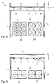
- Fig. 3a is a plan view of a device according to the invention 10 for depalletizing Bobinenstapeln 30, 35 shown schematically.
- Fig. 3b is a front view of the device 10 is shown.
- Such a device 10 is also generally used as a gantry robot designated.
- the device 10 for depalletizing bobbin stacks 30, 35 has a frame 12 with a horizontally movable Cross member 11.
- the cross member 11 is between the carriers of the Framework 12 is arranged.
- Between the frame 12th are two pallets 20, 25 with stacked bobbins 30, 35 placed.
- the laser-analogue sensors measure by means of phase correlation the light-time up to a distance of two meters with one Resolution in the millimeter range.
- the laser distance sensors 15th the bobbin search duration and a subsequent determination of the midpoints the bobbins 30, 35 reduced to a minimum, causing the Production speed of the device is increased.
- the device 10 ( Figure 3b) further includes a gripping device 45, by means of which the reels 30, 35 are removed from the pallets 20, 25 and a unwinding device or a buffer magazine be supplied.
- Fig. 3b are more Laser-analog sensors 15 on the cross member 11 of the portal robot arranged.
- Fig. 3c is another embodiment of the invention the apparatus 10 shown in the only one laser-analog sensor 15 is arranged on the gripper 45, so that the laser-analog sensor 15 and the gripper 45 are formed as a structural unit. As a result, the sensor 15 is moved together with the gripper 45.
- FIG. 4 shows a basic arrangement of laser-analog sensors or laser distance sensors 15 are shown. This arrangement is preferably used when more than two pallets 20, 25 are scanned. Here are the bobbins 30, 35 in rows arranged on the pallets 20, 25.
- 25 For each row of bobbins on the pallets 20, 25 becomes a laser range sensor 15 on the carrier (see cross member 11, Fig. 3a) of the arranged parallel to the pallet row parallel axis.
- 35 To scan the Bobbin stack 30, 35 passes over the carrier with the laser-analog sensors 15 just once the pallets, leaving after a single Pass the altitude values or distance values from a controller be recorded, processed and stored.
- the distance values become the respective axis positions during assigned to the test drive. Since the positions of the sensors 15 as Parameters are known, is the top position of each stack of bobbins known in three dimensions, so that of the gripping device of Portal robot a targeted to be taken bobbin.
- the use of laser distance sensors reduces the time significantly shortened for height determination or distance determination. In addition, higher accuracy is achieved by the laser sensors achieved.
- the number of laser distance sensors 15 corresponds the number of bobbin stack rows, with the range sensors are arranged adjustable to adapt to the respective Enable centerlines of the bobbin stacks.
- Fig. 5 is a circular arrangement of reels 51, 52 on a pallet 50 shown.
- the bobbins 51, 52 arranged in several layers.
- the dashed bobbins 52 form the lower layer, the gray-colored bobbins 51 are top.
- Fig. 6 is the schematic sequence of a scanning of pallets shown, with the bobbins on the pallets arranged in a circle are.
- the gripper head of the gantry robot moves with the arranged thereon laser-analog sensor from the parking position A. out to point L.
- the laser analog sensor After activating the laser analog sensor leads the gripping head above the reels 51 a circular path above the pallet 50 until it reaches the starting point L again. During this trip will be within short path intervals the distance values or distances and the associated coordinate values stored in a database. After that determines the Control from the measured data the starting position for a subsequent Journey with a laser light scanner.
- the gripper head from the point L to the parking position A moves.
- the gripper head moves out of the Parking position A to the point N above a pallet with reels 53 and scans the palette in the same way. From the sampling of circularly arranged bobbins will be the starting position for a subsequent laser scan determined.
- the invention is also suitable for Bobinenan glovesen, in where the reels do not line up.
- the device according to the invention has a controller which from the laser analog sensors which receives readings and to everyone Metric corresponding coordinates assigned. Further will be the readings are stored in a database, so that on the Basis of this database are the starting positions for measuring the bobbin cores are determined.
Landscapes
- Engineering & Computer Science (AREA)
- Mechanical Engineering (AREA)
- Length Measuring Devices By Optical Means (AREA)
- Manipulator (AREA)
Abstract
Description
- Fig. 1
- schematisch eine Draufsicht auf zwei Paletten;
- Fig. 2
- eine schematische Darstellung einer Bobine, bei der der Mittelpunkt gemäß dem Stand der Technik ermittelt wird;
- Fig. 3a, Fig. 3b
- schematisch eine Draufsicht bzw. Vorderansicht einer erfindungsgemäßen Vorrichtung;
- Fig. 3c
- eine Vorderansicht einer Vorrichtung gemäss einer weiteren Ausführung;
- Fig. 4
- eine prinzipielle Anordnung von Laserentfernungssensoren;
- Fig. 5
- eine kreisförmige Anordnung von Bobinen auf einer Palette und
- Fig. 6
- schematisch den Ablauf einer weiteren erfindungsgemäßen Palettenabtastung.
- 10
- Vorrichtung
- 11
- Querträger
- 12
- Rahmengestell
- 15
- Laserentfernungssensor
- 20
- Palette
- 25
- Palette
- 30
- Bobine
- 35
- Bobine
- 45
- Greifvorrichtung
- 50
- Palette
- 51
- Bobine
- 52
- Bobine
- 53
- Bobine
Claims (12)
- Vorrichtung (10) zum Entpalettieren eines Bobinenstapels (30, 35) mittels eines Greifers (45), dadurch gekennzeichnet, dass wenigstens ein Laserentfernungssensor (15) zur Messung der Höhe des Bobinenstapels (30, 35) vorgesehen ist.
- Vorrichtung (10) nach Anspruch 1, dadurch gekennzeichnet, dass der Laserentfernungssensor (15) zur Ermittlung der Entfernung zwischen dem Bobinenstapel (30, 35) und dem Greifer (45) vorgesehen ist.
- Vorrichtung (10) nach Anspruch 1 oder 2, dadurch gekennzeichnet, dass jeder Bobinenreihe des Bobinenstapels (30, 35) ein Laserentfernungssensor (15) zugeordnet ist.
- Vorrichtung (10) nach einem der Ansprüche 1 bis 3, dadurch gekennzeichnet, dass die Laserentfernungssensoren (15), insbesondere an einem Querträger (11), nebeneinander angeordnet sind.
- Vorrichtung (10) nach einem oder mehreren der Ansprüche 1 bis 4, dadurch gekennzeichnet, dass der Laserentfernungssensor (15) am Greifer (45) angeordnet ist.
- Vorrichtung (10) nach einem oder mehreren der Ansprüche 1 bis 5, dadurch gekennzeichnet, dass die Vorrichtung (10) als Portalroboter (10) ausgebildet ist.
- Vorrichtung (10) nach einem oder mehreren der Ansprüche 1 bis 6, dadurch gekennzeichnet, dass eine Steuerung zur Aufnahme und/oder Verarbeitung und/oder Speicherung der Entfernungswerte der Laserentfernungssensoren (15) vorgesehen ist.
- Verwendung eines Laserentfernungssensors (15) in einer Vorrichtung (10) zur Entpalettierung eines Bobinenstapels (30, 35) mittels eines Greifers (45), wobei der Laserentfernungssensor (15) zur Entfernungsmessung zwischen dem Bobinenstapel (30, 35) und dem Greifer (45) vorgesehen ist.
- Verwendung nach Anspruch 8, dadurch gekennzeichnet, dass jeder Reihe des Bobinenstapels (30, 35) ein Laserentfernungssensor (15) zugeordnet.
- Verwendung nach Anspruch 8 oder 9, dadurch gekennzeichnet, dass die Laserentfernungssensoren (15), insbesondere an einem Querträger (11), nebeneinander angeordnet sind.
- Verwendung nach einem oder mehreren der Ansprüche 8 bis 10, dadurch gekennzeichnet, dass die Vorrichtung (10) als Portalroboter ausgebildet ist.
- Verwendung nach einem oder mehreren der Ansprüche 7 bis 11, dadurch gekennzeichnet, dass eine Steuerung zur Aufnahme und/oder Verarbeitung und/oder Speicherung der Entfernungswerte der Laserentfernungssensoren (15) vorgesehen ist.
Priority Applications (1)
| Application Number | Priority Date | Filing Date | Title |
|---|---|---|---|
| EP03015827A EP1495998A1 (de) | 2003-07-10 | 2003-07-10 | Vorrichtung zum Entpalettieren eines Bobinenstapels mit einem Laserentfernungssensor und Verwendung eines Laserentfernungssensors zur Entpalettierung eines Bobinenstapels |
Applications Claiming Priority (1)
| Application Number | Priority Date | Filing Date | Title |
|---|---|---|---|
| EP03015827A EP1495998A1 (de) | 2003-07-10 | 2003-07-10 | Vorrichtung zum Entpalettieren eines Bobinenstapels mit einem Laserentfernungssensor und Verwendung eines Laserentfernungssensors zur Entpalettierung eines Bobinenstapels |
Publications (1)
| Publication Number | Publication Date |
|---|---|
| EP1495998A1 true EP1495998A1 (de) | 2005-01-12 |
Family
ID=33442784
Family Applications (1)
| Application Number | Title | Priority Date | Filing Date |
|---|---|---|---|
| EP03015827A Withdrawn EP1495998A1 (de) | 2003-07-10 | 2003-07-10 | Vorrichtung zum Entpalettieren eines Bobinenstapels mit einem Laserentfernungssensor und Verwendung eines Laserentfernungssensors zur Entpalettierung eines Bobinenstapels |
Country Status (1)
| Country | Link |
|---|---|
| EP (1) | EP1495998A1 (de) |
Cited By (4)
| Publication number | Priority date | Publication date | Assignee | Title |
|---|---|---|---|---|
| NL1032263C2 (nl) * | 2006-04-20 | 2007-10-23 | Greefs Wagen Carrosserie | Detectie-en besturingssysteem voor grote fruitkisten en werkwijze daarvoor. |
| EP1847490A1 (de) * | 2006-04-21 | 2007-10-24 | EISENMANN Anlagenbau GmbH & Co. KG | Vorrichtung und Verfahren zur automatischen Palettierung und/oder Depalettierung von Behältern |
| EP3281888A4 (de) * | 2015-05-22 | 2019-01-09 | Daifuku Co., Ltd. | Verfahren zur steuerung einer aufnahme-/abgabevorrichtung in einer flachen lagereinrichtung |
| CN115924453A (zh) * | 2022-12-30 | 2023-04-07 | 成都聚合智创科技有限公司 | 一种管件的取料方法 |
Citations (6)
| Publication number | Priority date | Publication date | Assignee | Title |
|---|---|---|---|---|
| US4521966A (en) * | 1982-09-14 | 1985-06-11 | Lidkopings Mekaniska Verkstads Ab | Method and apparatus for determining the position of the center of a circular object |
| DE3501692A1 (de) | 1985-01-19 | 1986-07-24 | Maschinenfabrik Fr. Niepmann GmbH u. Co, 5820 Gevelsberg | Vorrichtung zum entladen einzelner bobinen von einer unterlage |
| US5605432A (en) * | 1993-03-24 | 1997-02-25 | Hauni Maschinenbau Ag | Robot manipulator |
| US20010052708A1 (en) * | 1999-12-09 | 2001-12-20 | Kurt Schmalz | Vacuum grip system for gripping an object, and handling apparatus for handling an object using a vacuum grip system |
| DE10109446A1 (de) * | 2001-02-27 | 2002-09-05 | Focke & Co | Einrichtung zur Handhabung von Bobinen |
| WO2002092483A1 (en) * | 2001-05-11 | 2002-11-21 | G.D Societa' Per Azioni | Method and device for feeding reels to a machine |
-
2003
- 2003-07-10 EP EP03015827A patent/EP1495998A1/de not_active Withdrawn
Patent Citations (7)
| Publication number | Priority date | Publication date | Assignee | Title |
|---|---|---|---|---|
| US4521966A (en) * | 1982-09-14 | 1985-06-11 | Lidkopings Mekaniska Verkstads Ab | Method and apparatus for determining the position of the center of a circular object |
| DE3501692A1 (de) | 1985-01-19 | 1986-07-24 | Maschinenfabrik Fr. Niepmann GmbH u. Co, 5820 Gevelsberg | Vorrichtung zum entladen einzelner bobinen von einer unterlage |
| US4723884A (en) | 1985-01-19 | 1988-02-09 | Maschinenfabrik Fr. Niepmann Gmbh & Co. | Apparatus for unloading individual reels from a carrier member |
| US5605432A (en) * | 1993-03-24 | 1997-02-25 | Hauni Maschinenbau Ag | Robot manipulator |
| US20010052708A1 (en) * | 1999-12-09 | 2001-12-20 | Kurt Schmalz | Vacuum grip system for gripping an object, and handling apparatus for handling an object using a vacuum grip system |
| DE10109446A1 (de) * | 2001-02-27 | 2002-09-05 | Focke & Co | Einrichtung zur Handhabung von Bobinen |
| WO2002092483A1 (en) * | 2001-05-11 | 2002-11-21 | G.D Societa' Per Azioni | Method and device for feeding reels to a machine |
Cited By (5)
| Publication number | Priority date | Publication date | Assignee | Title |
|---|---|---|---|---|
| NL1032263C2 (nl) * | 2006-04-20 | 2007-10-23 | Greefs Wagen Carrosserie | Detectie-en besturingssysteem voor grote fruitkisten en werkwijze daarvoor. |
| EP1847491A1 (de) * | 2006-04-20 | 2007-10-24 | De Greef's Wagen-, Carrosserie- en Machinebouw B.V. | System und Verfahren zur Erfassung und Kontrolle von grossen Obstkisten |
| EP1847490A1 (de) * | 2006-04-21 | 2007-10-24 | EISENMANN Anlagenbau GmbH & Co. KG | Vorrichtung und Verfahren zur automatischen Palettierung und/oder Depalettierung von Behältern |
| EP3281888A4 (de) * | 2015-05-22 | 2019-01-09 | Daifuku Co., Ltd. | Verfahren zur steuerung einer aufnahme-/abgabevorrichtung in einer flachen lagereinrichtung |
| CN115924453A (zh) * | 2022-12-30 | 2023-04-07 | 成都聚合智创科技有限公司 | 一种管件的取料方法 |
Similar Documents
| Publication | Publication Date | Title |
|---|---|---|
| DE69518566T2 (de) | Verfahren zum führerlosen Betrieb eines Krans und Apparat dazu | |
| DE2746794C3 (de) | Vorrichtung zur Positionierung d;s Tragrahmens eines Verladegerätes für quaderförmiges Stückgut | |
| DE69223770T2 (de) | Sensorsystem für hochgenaue ausrichtung von komponenten | |
| DE19519741A1 (de) | Sensorik für einen Kran, insbesondere einen schienengebundenen Stapelkran oder Brückenkran | |
| DE19511324C2 (de) | Verfahren und Vorrichtung zur Qualitätsprüfung während der Herstellung von Betonsteinen | |
| DE3222654C2 (de) | ||
| DE69507362T2 (de) | Optisches Kontrollverfahren für Gegenstände | |
| EP0303722B1 (de) | Verfahren und Vorrichtung zum Erfassen und Behandeln von Fehlern in Stoffbahnen | |
| WO2011009150A1 (de) | Verfahren zur beladung eines ladungsträgers mit ladeeinheiten | |
| EP0703430B1 (de) | Verfahren zur Kalibrierung eines Koordinatenmessgerätes mit zwei rotatorischen Achsen | |
| EP1900665B1 (de) | Bestimmung einer Bobinenkernmitte bei einer Bobinenhandhabungsvorrichtung | |
| DE69209594T2 (de) | Verbesserungen an einem Wagen zum Zuführen eines zylindrischen Körpers in eine Wickelmaschine | |
| DE2941945A1 (de) | Verfahren und vorrichtung zur feststellung ausgebauchter und eingefallener seitenwaende sowie unrichtiger weiten bei paneelierten behaeltern | |
| EP0668237B1 (de) | Verfahren zur Förderung einer Last mittels eines Kranes | |
| EP0982252A1 (de) | Verfahren und Vorrichtung zum Erkennen von Druckmarken | |
| EP2578988A1 (de) | Kohärenzrasterinterferometer und Verfahren zur ortsaufgelösten optischen Vermessung der Oberflächengeometrie eines Objekts | |
| DE4336908A1 (de) | Wiegevorrichtung | |
| DE19752510B4 (de) | Einrichtung und Verfahren zur Erkennung und Unterscheidung geometrisch verschiedener Arten von fächerbildenden Auflagen in Kassetten und darauf abgelegten scheibenförmigen Objekten | |
| EP4483132A1 (de) | Messvorrichtung zur vermessung der ausrichtung und/oder orientierung von segmenten der energiezellen produzierenden industrie und verfahren zur herstellung von segmenten | |
| EP1495999A1 (de) | Vorrichtung zum Entpalettieren eines Bobinenstapels mit einem Laserdistanzmesssystem und Verwendung eines Laserdistanzmesssystem zur Erfassung von topografischen Daten eines Bobinenstapels | |
| DE2346965A1 (de) | Vorrichtung zum umbandeln eines raeumlich gekruemmten leiterstabes | |
| DE69414280T2 (de) | Verfahren und Einrichtung zum Bestimmen der Grösse und der Lage eines Walzkopfes | |
| EP1748004B1 (de) | Verfahren und Vorrichtung zum Vermessen und Positionieren eines quaderförmigen Stückguts | |
| DE102019110568A1 (de) | Transportvorrichtung und Verfahren zur Positionsüberwachung | |
| DE69424004T2 (de) | Trommelführungsmessverfahren zur genauen Ermittlung der Trommelführungsmessverfahren |
Legal Events
| Date | Code | Title | Description |
|---|---|---|---|
| PUAI | Public reference made under article 153(3) epc to a published international application that has entered the european phase |
Free format text: ORIGINAL CODE: 0009012 |
|
| AK | Designated contracting states |
Kind code of ref document: A1 Designated state(s): AT BE BG CH CY CZ DE DK EE ES FI FR GB GR HU IE IT LI LU MC NL PT RO SE SI SK TR |
|
| AX | Request for extension of the european patent |
Extension state: AL LT LV MK |
|
| 17P | Request for examination filed |
Effective date: 20050610 |
|
| AKX | Designation fees paid |
Designated state(s): AT BE BG CH CY CZ DE DK EE ES FI FR GB GR HU IE IT LI LU MC NL PT RO SE SI SK TR |
|
| RIN1 | Information on inventor provided before grant (corrected) |
Inventor name: STOECKER, RALF Inventor name: MICULIC, JOSIP |
|
| GRAP | Despatch of communication of intention to grant a patent |
Free format text: ORIGINAL CODE: EPIDOSNIGR1 |
|
| GRAS | Grant fee paid |
Free format text: ORIGINAL CODE: EPIDOSNIGR3 |
|
| STAA | Information on the status of an ep patent application or granted ep patent |
Free format text: STATUS: THE APPLICATION IS DEEMED TO BE WITHDRAWN |
|
| 18D | Application deemed to be withdrawn |
Effective date: 20070619 |