EP1495957A2 - Coupling system between frame and engine group of a motor vehicle - Google Patents
Coupling system between frame and engine group of a motor vehicle Download PDFInfo
- Publication number
- EP1495957A2 EP1495957A2 EP04076966A EP04076966A EP1495957A2 EP 1495957 A2 EP1495957 A2 EP 1495957A2 EP 04076966 A EP04076966 A EP 04076966A EP 04076966 A EP04076966 A EP 04076966A EP 1495957 A2 EP1495957 A2 EP 1495957A2
- Authority
- EP
- European Patent Office
- Prior art keywords
- group
- frame
- coupling system
- engine group
- engine
- Prior art date
- Legal status (The legal status is an assumption and is not a legal conclusion. Google has not performed a legal analysis and makes no representation as to the accuracy of the status listed.)
- Granted
Links
Images



Classifications
-
- B—PERFORMING OPERATIONS; TRANSPORTING
- B62—LAND VEHICLES FOR TRAVELLING OTHERWISE THAN ON RAILS
- B62M—RIDER PROPULSION OF WHEELED VEHICLES OR SLEDGES; POWERED PROPULSION OF SLEDGES OR SINGLE-TRACK CYCLES; TRANSMISSIONS SPECIALLY ADAPTED FOR SUCH VEHICLES
- B62M7/00—Motorcycles characterised by position of motor or engine
- B62M7/12—Motorcycles characterised by position of motor or engine with the engine beside or within the driven wheel
-
- B—PERFORMING OPERATIONS; TRANSPORTING
- B62—LAND VEHICLES FOR TRAVELLING OTHERWISE THAN ON RAILS
- B62K—CYCLES; CYCLE FRAMES; CYCLE STEERING DEVICES; RIDER-OPERATED TERMINAL CONTROLS SPECIALLY ADAPTED FOR CYCLES; CYCLE AXLE SUSPENSIONS; CYCLE SIDECARS, FORECARS, OR THE LIKE
- B62K11/00—Motorcycles, engine-assisted cycles or motor scooters with one or two wheels
- B62K11/02—Frames
- B62K11/04—Frames characterised by the engine being between front and rear wheels
-
- B—PERFORMING OPERATIONS; TRANSPORTING
- B62—LAND VEHICLES FOR TRAVELLING OTHERWISE THAN ON RAILS
- B62K—CYCLES; CYCLE FRAMES; CYCLE STEERING DEVICES; RIDER-OPERATED TERMINAL CONTROLS SPECIALLY ADAPTED FOR CYCLES; CYCLE AXLE SUSPENSIONS; CYCLE SIDECARS, FORECARS, OR THE LIKE
- B62K11/00—Motorcycles, engine-assisted cycles or motor scooters with one or two wheels
- B62K11/02—Frames
- B62K11/10—Frames characterised by the engine being over or beside driven rear wheel
-
- B—PERFORMING OPERATIONS; TRANSPORTING
- B62—LAND VEHICLES FOR TRAVELLING OTHERWISE THAN ON RAILS
- B62K—CYCLES; CYCLE FRAMES; CYCLE STEERING DEVICES; RIDER-OPERATED TERMINAL CONTROLS SPECIALLY ADAPTED FOR CYCLES; CYCLE AXLE SUSPENSIONS; CYCLE SIDECARS, FORECARS, OR THE LIKE
- B62K2202/00—Motorised scooters
Definitions
- the present invention concerns a coupling system between frame and engine group of a motor vehicle.
- the invention concerns a system of the aforementioned type, studied and realised in particular for reducing the passage of the vibrations produced for example by an internal combustion engine, and the torsional effects with respect to the vertical plane of a motorcycle, but which can be used for any system or means equivalent to the one indicated.
- the purpose of the present invention is that of solving the problems of the prior art providing a coupling system between engine group and frame that allows the passage of vibrations between frame and engine group to be effectively reduced.
- Another purpose of the present invention is that of allowing the installation of the engine group in a central position with respect to the vehicle, instead of a position set back towards the rear as current designs foresee.
- a further purpose of the present invention is that of realising a coupling system between engine group and frame that is simple and cost-effective to construct.
- a coupling system comprises a frame and an engine group and is characterised in that it comprises at least one front connection group and at least two rear connection groups; the two rear connection groups being placed laterally on the opposite sides of the engine group at the drive shaft to couple with the frame so as to exclusively allow movements of the engine group in the vertical plane of the motor vehicle.
- each rear connection group comprises at least one roller unit device.
- each rear connection group comprises at least one silentblock.
- each rear connection group comprises at least one roller unit device and at least one silentblock coupled together.
- each rear connection group is coupled with the frame by means of a support bracket.
- the rear connection groups comprise articulations pivoted to the frame and to the two opposite sides of the engine.
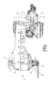
- the engine group 1 is connected to the frame 2 by means of two rear connection groups 3, 4 and a front connection group 5.
- the rear connection groups 3, 4 are arranged laterally to the crankcase 8 of the engine group 1 in a corresponding position, but on opposite sides of the crankcase itself 8.
- the engine group 1 is positioned in a central position with respect to the motor vehicle, unlike the solutions according to the prior art that foresee a position set back towards the rear part. More specifically, the engine group is positioned at the central part of the vehicle, in such a way reducing the formation of turning torques due to an increase in the distance between point of application of the weight force of the engine group 1 and centre of mass of the scooter.
- connection group 3 is arranged laterally to the crankcase 8 at the drive shaft 16, whereas the remaining connection group 4 is again arranged at the drive shaft 16, but on the opposite side of the crankcase itself 8.
- connection group 3 again as can be seen in figure 2, is fitted directly onto the drive shaft 16 downstream of a transmission coil 17 of the motion to the chain 18.
- connection group 4 On the opposite side of the crankcase 8, in a corresponding position, as stated previously, the other connection group 4 is arranged fixedly connected to the engine group 1 by means of a projecting pin 7 integral with the crankcase 8.
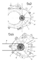
- Figures 3 and 4 respectively show the two rear connection groups 3, 4 according to the present invention, each group 3, 4 comprising a roller unit 20, 20' and a silentblock 21, 21'.
- the roller unit is the mechanical member used for the connection between the silentblock 21, 21' and the drive shaft 16 or the projecting pin 7.
- the roller unit foresees two concentric sleeves, made integral, respectively, with the silentblock 21, 21' and with the drive shaft 16 or with the pin 7 between which rolling rollers are arranged.
- the silentblock really responsible for the damping of vibrations, at least partially contains the roller unit and is fixedly connected to it by means of a forced coupling, alternatively by welding or another coupling system.
- connection groups can be made up of just the silentblock 21, 21' or just the roller units 20, 20'.
- connection groups 3, 4 are, in turn, coupled with support brackets 13 fixed to the frame so as to ensure exclusively movements of the engine group, substantially in the vertical plane.
- connection groups 3, 4 consist of two articulations 25, 25' pivoted at one end to the frame 2 and at the remaining end to the engine group 1 so as to allow the movement of the engine only in the vertical plane, in other words opposing the belt pull on the horizontal plane.
- the articulation 25, consisting of a connecting-rod, is pivoted at one end thereof to the frame 2 and at the remaining end on the drive shaft 16, whereas the articulation 25', also consisting of a connecting-rod, is pivoted at one end thereof to the frame 2 and at the remaining end on the pin 7.
- the articulations 25, 25', respectively, can be pivoted on the drive shaft 16 and on the pin 7 directly or through the interposition of a silentblock or a roller unit.
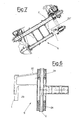
- the two articulations or connecting-rods 25, 25' can also, but not necessarily, be connected together by the tube 31 to form a single articulated system, as shown in figure 9.
- connection group 5 In a front position, as stated previously, the coupling system foresees a further connection group 5.
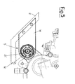
- an anti-vibration silentblock 21" is foreseen as a front connection group 5, inserted on a transversal tube 12 integral with the engine group 1.
- the silentblock is in turn fixedly connected, through the support bracket 14, to the frame 2.
- an oscillating arm 22 or a double oscillating arm 22' can be foreseen as front connection group 5.
- the oscillating arm 22 is fixedly connected at one end to the engine group 1 and is pivoted, at the remaining end, to the frame 2.
- a transversal tube 23 is foreseen integral with the engine group 1, whereas to assist the damping of vibrations two silentblocks 24 are foreseen between oscillating arm 22 and frame 2.
- connection group 5 can comprise a shaped bracket pivoted at the engine group and at the frame at many points.
- one or more connecting-rods and at least one spring suspension are foreseen.
- silentblocks can also be foreseen placed between spring suspension and shaped bracket.
- connection group 5 in which a pair of articulations 26 and 26' is pivoted on the frame 2 to allow the attachment of the front part of the engine group 1 so as to eliminate the horizontal movements of the engine group.
- the two articulations or connecting-rods 26, 26' can also, but not necessarily, be connected together by a tube 30 so as to form a single articulated system, as shown in figure 9.
- the two connecting-rods 26, 26' extend with the projecting portion 32 to engage the two abutment buffers 27 and 28.
- the two abutment buffers 27, 28 are supported and kept integral with the frame through the bracket 29.
- the fundamental advantage of the present invention is that of reducing the passage of vibrations from the engine to the vehicle.
- the rear connections 3, 4 between frame and engine group 1 are, therefore, carried out directly through roller units and/or silentblocks and/or articulations allowing the reliability of the coupling to be increased and reducing phenomena of amplification of the vibrations.
- the silentblocks also allow an elastic coupling with respect to the frame.
- the different radial, axial and torsional rigidities of the silentblocks and of the front connection group 5 allows the engine group to be left the freedom of movement necessary for limiting the passage of vibrations and for counteracting the movements that influence the riding of the vehicle.
- the coupling system according to the present invention allows there to be transmission and rear suspension arm not rigidly assembled to the engine group, as vice-versa happens in frame-engine group coupling systems according to the prior art.
Landscapes
- Engineering & Computer Science (AREA)
- Mechanical Engineering (AREA)
- Chemical & Material Sciences (AREA)
- Combustion & Propulsion (AREA)
- Transportation (AREA)
- Arrangement Or Mounting Of Propulsion Units For Vehicles (AREA)
- Vibration Prevention Devices (AREA)
Abstract
Description
Claims (17)
- Coupling system between frame (2) and engine group (1) of a motor vehicle, characterised in that it comprises at least one front connection group (5) and at least two rear connection groups (3, 4); said two rear connection groups (3, 4) being placed laterally on the opposite sides of said engine group (1) so as to couple with said frame (2) to exclusively allow movements of said engine group (1) substantially in the vertical plane of the motor vehicle.
- Coupling system according to claim 1, characterised in that said two rear connection groups (3, 4) are placed laterally on opposite sides of said engine group (1) at the drive shaft (16).
- Coupling system according to claim 1 or 2, characterised in that each rear connection group (3, 4) comprises at least one roller unit device (20, 20').
- Coupling system according to claim 1 or 2, characterised in that each rear connection group (3, 4) comprises at least one silentblock (21, 21').
- Coupling system according to claim 1 or 2, characterised in that each rear connection group (3, 4) comprises at least one roller unit device (20, 20') and at least one silentblock (21, 21') coupled together.
- Coupling system according to any one of the previous claims, characterised in that each rear connection group (3, 4) is coupled with the frame by means of a support bracket (13).
- Coupling system according to claim 1 or 2, characterised in that each rear connection group (3, 4) comprises at least one articulation (25, 25') pivoted at said frame (2) and at said engine group (1).
- Coupling system according to claim 7, characterised in that said at least one articulation (25, 25') comprises a connecting-rod.
- Coupling system according to claims 7 and 8, characterised in that each articulation (25, 25') is connected to the other through a tube 30 to form a single articulated system.
- Coupling system according to any one of the previous claims, characterised in that a rear connection group (3) is directly inserted on the drive shaft (16) and in that the other rear connection group (4) is inserted on a pin element (7) projecting from the engine group (1) on the opposite side to that of said drive shaft (16).
- Coupling system according to any one of the previous claims, characterised in that said front connection group (5) comprises at least one silentblock (21") inserted on a transversal tube (12) integral with the engine group (1).
- Coupling system according to claim 11, characterised in that said front connection group (5) is coupled with said frame (2) through a support bracket (14) suitable for engaging said silentblock (21").
- Coupling system according to any one of claims 1 to 10, characterised in that said front connection group (5) comprises at least one oscillating arm (22) fixedly connected to the engine group (1) and pivoted at the frame (2).
- Coupling system according to any one of claims 1 to 10, characterised in that said front connection group (5) comprises at least one double oscillating arm (22') pivoted at one end to the engine group (1) and at the other end to the frame (2).
- Coupling system according to any one of claims 1 to 10, characterised in that said front connection group (5) comprises at least two articulations (26, 26'), pivoted to the engine group (1) and to the frame (2), and at least one abutment buffer (27, 28) kept integral with said frame (2) through a bracket 29 fixed to said frame (2).
- Coupling system according to claim 15, characterised in that said at least two articulations (26, 26') each comprise at least one connecting-rod (26 and 26') pivoted to the engine group (1) and to the frame (2) and in engagement with said at least one buffer (27, 28).
- Coupling system according to any one of claims 15 to 16, characterised in that the articulations (26, 26') are connected together by means of a tube (31) to form a single articulated system.
Priority Applications (3)
| Application Number | Priority Date | Filing Date | Title |
|---|---|---|---|
| PL04076966T PL1495957T3 (en) | 2003-07-09 | 2004-07-07 | Coupling system between frame and engine group of a motor vehicle |
| SI200430612T SI1495957T1 (en) | 2003-07-09 | 2004-07-07 | Coupling system between frame and engine group of a motor vehicle |
| CY20081100220T CY1107213T1 (en) | 2003-07-09 | 2008-02-26 | FRAMEWORK SYSTEM COLLABORATION AND TOTAL ENGINE OF A CAR |
Applications Claiming Priority (2)
| Application Number | Priority Date | Filing Date | Title |
|---|---|---|---|
| IT001400A ITMI20031400A1 (en) | 2003-07-09 | 2003-07-09 | COUPLING SYSTEM BETWEEN CHASSIS AND MOTOR UNIT OF A MOTOR WHEEL. |
| ITMI20031400 | 2003-07-09 |
Publications (3)
| Publication Number | Publication Date |
|---|---|
| EP1495957A2 true EP1495957A2 (en) | 2005-01-12 |
| EP1495957A3 EP1495957A3 (en) | 2006-04-05 |
| EP1495957B1 EP1495957B1 (en) | 2007-11-28 |
Family
ID=33446437
Family Applications (1)
| Application Number | Title | Priority Date | Filing Date |
|---|---|---|---|
| EP04076966A Expired - Lifetime EP1495957B1 (en) | 2003-07-09 | 2004-07-07 | Coupling system between frame and engine group of a motor vehicle |
Country Status (11)
| Country | Link |
|---|---|
| EP (1) | EP1495957B1 (en) |
| CN (1) | CN100391781C (en) |
| CY (1) | CY1107213T1 (en) |
| DE (1) | DE602004010331T2 (en) |
| DK (1) | DK1495957T3 (en) |
| ES (1) | ES2298673T3 (en) |
| IT (1) | ITMI20031400A1 (en) |
| PL (1) | PL1495957T3 (en) |
| PT (1) | PT1495957E (en) |
| SI (1) | SI1495957T1 (en) |
| TW (1) | TW200508063A (en) |
Cited By (1)
| Publication number | Priority date | Publication date | Assignee | Title |
|---|---|---|---|---|
| EP1693293A1 (en) * | 2005-02-18 | 2006-08-23 | PIAGGIO & C. S.p.A. | Transmission system |
Families Citing this family (1)
| Publication number | Priority date | Publication date | Assignee | Title |
|---|---|---|---|---|
| JP4532380B2 (en) * | 2005-09-29 | 2010-08-25 | 本田技研工業株式会社 | Motorcycle |
Family Cites Families (9)
| Publication number | Priority date | Publication date | Assignee | Title |
|---|---|---|---|---|
| US2950625A (en) * | 1957-03-14 | 1960-08-30 | Motobecane Ateliers | Transmission using a change speed gear with a single expandible pulley |
| GB1219896A (en) * | 1967-06-08 | 1971-01-20 | Norton Villiers Ltd | Improvements in or relating to chain driven vehicles |
| US3722612A (en) * | 1970-06-17 | 1973-03-27 | Norton Villiers Ltd | Chain driven vehicles |
| JPS5613266A (en) * | 1979-07-12 | 1981-02-09 | Yamaha Motor Co Ltd | Method of mounting engine |
| AU539919B2 (en) * | 1980-09-22 | 1984-10-25 | Honda Giken Kogyo Kabushiki Kaisha | Motorcycle frame |
| US4487285A (en) * | 1982-01-12 | 1984-12-11 | Honda Motor Co., Ltd. | Engine suspension system |
| JPH0698948B2 (en) * | 1985-08-16 | 1994-12-07 | ヤマハ発動機株式会社 | Anti-vibration device for vehicle engine |
| JPH1016573A (en) * | 1996-06-28 | 1998-01-20 | Suzuki Motor Corp | Engine mount bracket |
| CN2294907Y (en) * | 1997-03-21 | 1998-10-21 | 光阳工业股份有限公司 | motorcycle engine suspension |
-
2003
- 2003-07-09 IT IT001400A patent/ITMI20031400A1/en unknown
-
2004
- 2004-07-05 TW TW093120125A patent/TW200508063A/en unknown
- 2004-07-07 DK DK04076966T patent/DK1495957T3/en active
- 2004-07-07 EP EP04076966A patent/EP1495957B1/en not_active Expired - Lifetime
- 2004-07-07 ES ES04076966T patent/ES2298673T3/en not_active Expired - Lifetime
- 2004-07-07 SI SI200430612T patent/SI1495957T1/en unknown
- 2004-07-07 PT PT04076966T patent/PT1495957E/en unknown
- 2004-07-07 PL PL04076966T patent/PL1495957T3/en unknown
- 2004-07-07 DE DE602004010331T patent/DE602004010331T2/en not_active Expired - Fee Related
- 2004-07-09 CN CNB2004100550756A patent/CN100391781C/en not_active Expired - Fee Related
-
2008
- 2008-02-26 CY CY20081100220T patent/CY1107213T1/en unknown
Cited By (1)
| Publication number | Priority date | Publication date | Assignee | Title |
|---|---|---|---|---|
| EP1693293A1 (en) * | 2005-02-18 | 2006-08-23 | PIAGGIO & C. S.p.A. | Transmission system |
Also Published As
| Publication number | Publication date |
|---|---|
| EP1495957B1 (en) | 2007-11-28 |
| EP1495957A3 (en) | 2006-04-05 |
| SI1495957T1 (en) | 2008-06-30 |
| ITMI20031400A1 (en) | 2005-01-10 |
| CY1107213T1 (en) | 2012-11-21 |
| CN1576152A (en) | 2005-02-09 |
| PL1495957T3 (en) | 2008-04-30 |
| DE602004010331D1 (en) | 2008-01-10 |
| TW200508063A (en) | 2005-03-01 |
| PT1495957E (en) | 2008-03-10 |
| DK1495957T3 (en) | 2008-04-07 |
| DE602004010331T2 (en) | 2008-10-16 |
| ES2298673T3 (en) | 2008-05-16 |
| CN100391781C (en) | 2008-06-04 |
Similar Documents
| Publication | Publication Date | Title |
|---|---|---|
| EP1747982B1 (en) | Two-wheeled vehicle | |
| EP1826110B1 (en) | Motorcycle with drive shaft | |
| JP4837531B2 (en) | Rear wheel suspension structure | |
| US7730988B2 (en) | Rear wheel suspension for a motorcycle and swing arm attachment structure for a motorcycle | |
| CA2566022C (en) | Steering shaft support structure and vehicle | |
| US20040035628A1 (en) | Motortricycle with oscillation mechanism | |
| JP2018131001A (en) | Motorcycle frame | |
| EP1514787B1 (en) | Swing arm suspension | |
| US7641015B2 (en) | Motorcycle | |
| JP4271641B2 (en) | How to replace the rear part of the body frame | |
| EP1495957B1 (en) | Coupling system between frame and engine group of a motor vehicle | |
| CN101463749B (en) | motorcycle exhaust | |
| JP6251615B2 (en) | Suspension device for saddle riding type vehicle | |
| JP3554362B2 (en) | Exhaust pipe system support structure for vehicles | |
| CN118977797A (en) | Saddle-type vehicle and coupling bracket used for the saddle-type vehicle | |
| JP2009073403A (en) | Saddle-type vehicle with electric power steering device | |
| JP4671778B2 (en) | Motorcycle rear wheel suspension system | |
| EP1481886B1 (en) | Coupling system between frame and rear engine-suspension group of a motor vehicle | |
| WO2011135221A1 (en) | Hybrid vehicle chassis that forms a frame | |
| JP7275549B2 (en) | Support structure for vehicle power unit | |
| US7950490B2 (en) | Four-wheel vehicle suspension arrangement | |
| JP2003226284A (en) | Motorcycle engine mount structure | |
| EP1693293B1 (en) | Transmission system | |
| JP6134243B2 (en) | Suspension structure for saddle riding type vehicles | |
| JP2025044057A (en) | vehicle |
Legal Events
| Date | Code | Title | Description |
|---|---|---|---|
| PUAI | Public reference made under article 153(3) epc to a published international application that has entered the european phase |
Free format text: ORIGINAL CODE: 0009012 |
|
| AK | Designated contracting states |
Kind code of ref document: A2 Designated state(s): AT BE BG CH CY CZ DE DK EE ES FI FR GB GR HU IE IT LI LU MC NL PL PT RO SE SI SK TR |
|
| AX | Request for extension of the european patent |
Extension state: AL HR LT LV MK |
|
| PUAL | Search report despatched |
Free format text: ORIGINAL CODE: 0009013 |
|
| AK | Designated contracting states |
Kind code of ref document: A3 Designated state(s): AT BE BG CH CY CZ DE DK EE ES FI FR GB GR HU IE IT LI LU MC NL PL PT RO SE SI SK TR |
|
| AX | Request for extension of the european patent |
Extension state: AL HR LT LV MK |
|
| 17P | Request for examination filed |
Effective date: 20060921 |
|
| 17Q | First examination report despatched |
Effective date: 20061023 |
|
| AKX | Designation fees paid |
Designated state(s): AT BE BG CH CY CZ DE DK EE ES FI FR GB GR HU IE IT LI LU MC NL PL PT RO SE SI SK TR |
|
| 17Q | First examination report despatched |
Effective date: 20061023 |
|
| GRAP | Despatch of communication of intention to grant a patent |
Free format text: ORIGINAL CODE: EPIDOSNIGR1 |
|
| GRAS | Grant fee paid |
Free format text: ORIGINAL CODE: EPIDOSNIGR3 |
|
| GRAA | (expected) grant |
Free format text: ORIGINAL CODE: 0009210 |
|
| AK | Designated contracting states |
Kind code of ref document: B1 Designated state(s): AT BE BG CH CY CZ DE DK EE ES FI FR GB GR HU IE IT LI LU MC NL PL PT RO SE SI SK TR |
|
| REG | Reference to a national code |
Ref country code: GB Ref legal event code: FG4D |
|
| REG | Reference to a national code |
Ref country code: IE Ref legal event code: FG4D |
|
| REG | Reference to a national code |
Ref country code: CH Ref legal event code: EP |
|
| REF | Corresponds to: |
Ref document number: 602004010331 Country of ref document: DE Date of ref document: 20080110 Kind code of ref document: P |
|
| REG | Reference to a national code |
Ref country code: RO Ref legal event code: EPE |
|
| REG | Reference to a national code |
Ref country code: PT Ref legal event code: SC4A Free format text: AVAILABILITY OF NATIONAL TRANSLATION Effective date: 20080228 |
|
| REG | Reference to a national code |
Ref country code: SE Ref legal event code: TRGR |
|
| REG | Reference to a national code |
Ref country code: GR Ref legal event code: EP Ref document number: 20080400563 Country of ref document: GR |
|
| REG | Reference to a national code |
Ref country code: CH Ref legal event code: NV Representative=s name: A. BRAUN, BRAUN, HERITIER, ESCHMANN AG PATENTANWAE |
|
| REG | Reference to a national code |
Ref country code: DK Ref legal event code: T3 |
|
| REG | Reference to a national code |
Ref country code: PL Ref legal event code: T3 |
|
| REG | Reference to a national code |
Ref country code: ES Ref legal event code: FG2A Ref document number: 2298673 Country of ref document: ES Kind code of ref document: T3 |
|
| REG | Reference to a national code |
Ref country code: CH Ref legal event code: PFA Owner name: PIAGGIO & C. S.P.A. Free format text: PIAGGIO & C. S.P.A.#VIA RINALDO PIAGGIO 25#56025 PONTEDERA (PISA) (IT) -TRANSFER TO- PIAGGIO & C. S.P.A.#VIA RINALDO PIAGGIO 25#56025 PONTEDERA (PISA) (IT) |
|
| PGFP | Annual fee paid to national office [announced via postgrant information from national office to epo] |
Ref country code: CZ Payment date: 20080626 Year of fee payment: 5 |
|
| ET | Fr: translation filed | ||
| PGFP | Annual fee paid to national office [announced via postgrant information from national office to epo] |
Ref country code: RO Payment date: 20080612 Year of fee payment: 5 |
|
| REG | Reference to a national code |
Ref country code: HU Ref legal event code: AG4A Ref document number: E003312 Country of ref document: HU |
|
| PGFP | Annual fee paid to national office [announced via postgrant information from national office to epo] |
Ref country code: BG Payment date: 20080622 Year of fee payment: 5 Ref country code: MC Payment date: 20080627 Year of fee payment: 5 Ref country code: TR Payment date: 20080612 Year of fee payment: 5 Ref country code: PT Payment date: 20080627 Year of fee payment: 5 Ref country code: PL Payment date: 20080609 Year of fee payment: 5 Ref country code: EE Payment date: 20080605 Year of fee payment: 5 |
|
| PLBE | No opposition filed within time limit |
Free format text: ORIGINAL CODE: 0009261 |
|
| STAA | Information on the status of an ep patent application or granted ep patent |
Free format text: STATUS: NO OPPOSITION FILED WITHIN TIME LIMIT |
|
| PGFP | Annual fee paid to national office [announced via postgrant information from national office to epo] |
Ref country code: SI Payment date: 20080701 Year of fee payment: 5 Ref country code: LU Payment date: 20080721 Year of fee payment: 5 Ref country code: ES Payment date: 20080821 Year of fee payment: 5 Ref country code: DK Payment date: 20080721 Year of fee payment: 5 Ref country code: DE Payment date: 20080711 Year of fee payment: 5 Ref country code: CH Payment date: 20080912 Year of fee payment: 5 |
|
| 26N | No opposition filed |
Effective date: 20080829 |
|
| PGFP | Annual fee paid to national office [announced via postgrant information from national office to epo] |
Ref country code: SK Payment date: 20080703 Year of fee payment: 5 Ref country code: NL Payment date: 20080703 Year of fee payment: 5 Ref country code: IT Payment date: 20080716 Year of fee payment: 5 Ref country code: IE Payment date: 20080714 Year of fee payment: 5 Ref country code: FR Payment date: 20080718 Year of fee payment: 5 Ref country code: FI Payment date: 20080714 Year of fee payment: 5 Ref country code: AT Payment date: 20080711 Year of fee payment: 5 |
|
| REG | Reference to a national code |
Ref country code: EE Ref legal event code: HC1A Ref document number: E001793 Country of ref document: EE |
|
| PGFP | Annual fee paid to national office [announced via postgrant information from national office to epo] |
Ref country code: GB Payment date: 20080709 Year of fee payment: 5 Ref country code: CY Payment date: 20080630 Year of fee payment: 5 |
|
| PGFP | Annual fee paid to national office [announced via postgrant information from national office to epo] |
Ref country code: SE Payment date: 20080709 Year of fee payment: 5 |
|
| PGFP | Annual fee paid to national office [announced via postgrant information from national office to epo] |
Ref country code: GR Payment date: 20080619 Year of fee payment: 5 |
|
| PGFP | Annual fee paid to national office [announced via postgrant information from national office to epo] |
Ref country code: BE Payment date: 20090126 Year of fee payment: 5 |
|
| REG | Reference to a national code |
Ref country code: PT Ref legal event code: MM4A Free format text: LAPSE DUE TO NON-PAYMENT OF FEES Effective date: 20100107 |
|
| BERE | Be: lapsed |
Owner name: PIAGGIO & C. S.P.A. Effective date: 20090731 |
|
| PG25 | Lapsed in a contracting state [announced via postgrant information from national office to epo] |
Ref country code: MC Free format text: LAPSE BECAUSE OF NON-PAYMENT OF DUE FEES Effective date: 20090731 |
|
| REG | Reference to a national code |
Ref country code: CH Ref legal event code: PL |
|
| REG | Reference to a national code |
Ref country code: DK Ref legal event code: EBP |
|
| EUG | Se: european patent has lapsed | ||
| GBPC | Gb: european patent ceased through non-payment of renewal fee |
Effective date: 20090707 |
|
| PGFP | Annual fee paid to national office [announced via postgrant information from national office to epo] |
Ref country code: HU Payment date: 20081001 Year of fee payment: 5 |
|
| NLV4 | Nl: lapsed or anulled due to non-payment of the annual fee |
Effective date: 20100201 |
|
| REG | Reference to a national code |
Ref country code: SK Ref legal event code: MM4A Ref document number: E 3107 Country of ref document: SK Effective date: 20090707 |
|
| REG | Reference to a national code |
Ref country code: EE Ref legal event code: MM4A Ref document number: E001793 Country of ref document: EE Effective date: 20090731 |
|
| REG | Reference to a national code |
Ref country code: FR Ref legal event code: ST Effective date: 20100331 |
|
| PG25 | Lapsed in a contracting state [announced via postgrant information from national office to epo] |
Ref country code: RO Free format text: LAPSE BECAUSE OF NON-PAYMENT OF DUE FEES Effective date: 20090707 Ref country code: PT Free format text: LAPSE BECAUSE OF NON-PAYMENT OF DUE FEES Effective date: 20100107 Ref country code: LI Free format text: LAPSE BECAUSE OF NON-PAYMENT OF DUE FEES Effective date: 20090731 Ref country code: HU Free format text: LAPSE BECAUSE OF NON-PAYMENT OF DUE FEES Effective date: 20090708 Ref country code: FR Free format text: LAPSE BECAUSE OF NON-PAYMENT OF DUE FEES Effective date: 20090731 Ref country code: FI Free format text: LAPSE BECAUSE OF NON-PAYMENT OF DUE FEES Effective date: 20090707 Ref country code: EE Free format text: LAPSE BECAUSE OF NON-PAYMENT OF DUE FEES Effective date: 20090731 Ref country code: CZ Free format text: LAPSE BECAUSE OF NON-PAYMENT OF DUE FEES Effective date: 20090707 Ref country code: CH Free format text: LAPSE BECAUSE OF NON-PAYMENT OF DUE FEES Effective date: 20090731 |
|
| REG | Reference to a national code |
Ref country code: SI Ref legal event code: KO00 Effective date: 20100315 |
|
| PG25 | Lapsed in a contracting state [announced via postgrant information from national office to epo] |
Ref country code: SK Free format text: LAPSE BECAUSE OF NON-PAYMENT OF DUE FEES Effective date: 20090707 Ref country code: SI Free format text: LAPSE BECAUSE OF NON-PAYMENT OF DUE FEES Effective date: 20090708 Ref country code: GB Free format text: LAPSE BECAUSE OF NON-PAYMENT OF DUE FEES Effective date: 20090707 Ref country code: CY Free format text: LAPSE BECAUSE OF NON-PAYMENT OF DUE FEES Effective date: 20090707 |
|
| PG25 | Lapsed in a contracting state [announced via postgrant information from national office to epo] |
Ref country code: DE Free format text: LAPSE BECAUSE OF NON-PAYMENT OF DUE FEES Effective date: 20100202 Ref country code: BE Free format text: LAPSE BECAUSE OF NON-PAYMENT OF DUE FEES Effective date: 20090731 Ref country code: AT Free format text: LAPSE BECAUSE OF NON-PAYMENT OF DUE FEES Effective date: 20090707 |
|
| PG25 | Lapsed in a contracting state [announced via postgrant information from national office to epo] |
Ref country code: IE Free format text: LAPSE BECAUSE OF NON-PAYMENT OF DUE FEES Effective date: 20090707 Ref country code: DK Free format text: LAPSE BECAUSE OF NON-PAYMENT OF DUE FEES Effective date: 20090731 Ref country code: BG Free format text: LAPSE BECAUSE OF THE APPLICANT RENOUNCES Effective date: 20100131 |
|
| REG | Reference to a national code |
Ref country code: ES Ref legal event code: FD2A Effective date: 20090708 |
|
| PG25 | Lapsed in a contracting state [announced via postgrant information from national office to epo] |
Ref country code: GR Free format text: LAPSE BECAUSE OF NON-PAYMENT OF DUE FEES Effective date: 20100204 Ref country code: ES Free format text: LAPSE BECAUSE OF NON-PAYMENT OF DUE FEES Effective date: 20090708 |
|
| PG25 | Lapsed in a contracting state [announced via postgrant information from national office to epo] |
Ref country code: IT Free format text: LAPSE BECAUSE OF NON-PAYMENT OF DUE FEES Effective date: 20090707 |
|
| PG25 | Lapsed in a contracting state [announced via postgrant information from national office to epo] |
Ref country code: LU Free format text: LAPSE BECAUSE OF NON-PAYMENT OF DUE FEES Effective date: 20090707 |
|
| PG25 | Lapsed in a contracting state [announced via postgrant information from national office to epo] |
Ref country code: SE Free format text: LAPSE BECAUSE OF NON-PAYMENT OF DUE FEES Effective date: 20090708 Ref country code: PL Free format text: LAPSE BECAUSE OF NON-PAYMENT OF DUE FEES Effective date: 20090707 |
|
| REG | Reference to a national code |
Ref country code: PL Ref legal event code: LAPE |
|
| PG25 | Lapsed in a contracting state [announced via postgrant information from national office to epo] |
Ref country code: NL Free format text: LAPSE BECAUSE OF NON-PAYMENT OF DUE FEES Effective date: 20100201 |
|
| PG25 | Lapsed in a contracting state [announced via postgrant information from national office to epo] |
Ref country code: TR Free format text: LAPSE BECAUSE OF NON-PAYMENT OF DUE FEES Effective date: 20090707 |