EP1495920A1 - Überrollbügelanordnung für ein Kraftfahrzeug - Google Patents
Überrollbügelanordnung für ein Kraftfahrzeug Download PDFInfo
- Publication number
- EP1495920A1 EP1495920A1 EP04010517A EP04010517A EP1495920A1 EP 1495920 A1 EP1495920 A1 EP 1495920A1 EP 04010517 A EP04010517 A EP 04010517A EP 04010517 A EP04010517 A EP 04010517A EP 1495920 A1 EP1495920 A1 EP 1495920A1
- Authority
- EP
- European Patent Office
- Prior art keywords
- hollow profile
- roll bar
- section
- sections
- wall thickness
- Prior art date
- Legal status (The legal status is an assumption and is not a legal conclusion. Google has not performed a legal analysis and makes no representation as to the accuracy of the status listed.)
- Granted
Links
Images
Classifications
-
- B—PERFORMING OPERATIONS; TRANSPORTING
- B60—VEHICLES IN GENERAL
- B60R—VEHICLES, VEHICLE FITTINGS, OR VEHICLE PARTS, NOT OTHERWISE PROVIDED FOR
- B60R21/00—Arrangements or fittings on vehicles for protecting or preventing injuries to occupants or pedestrians in case of accidents or other traffic risks
- B60R21/02—Occupant safety arrangements or fittings, e.g. crash pads
- B60R21/13—Roll-over protection
- B60R2021/132—Roll bars for convertible vehicles
Definitions
- a generic roll bar assembly is known, the For example, a weld nut as a fastener for Gurtumlenkbeschlag having.
- the roll bar assembly is made up of several hollow profile sections composed, wherein the two-part cross strut in a middle Compound area is reinforced by strength that several of the Hollow profile sections in one another.
- DE 94 16 772 U1 is concerned with a roll bar arrangement, in which pushed a cross strut pipe sections with U-shaped curved roll bars are. Due to the larger outer diameter of the roll bar results in a paragraph the lateral surface of the crossbar.
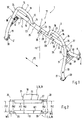
- Fig. 1 shows a roll bar assembly 1, the principle of two with each other connected frame parts 2 and 3 is composed.
- the first frame part 2 comprises a transverse strut 4, which with the structure of a not shown here Motor vehicle is connectable.
- first attachment brackets 7 and 8 attached at the free ends 5 and 6 of the frame part. 2 or the cross strut 4 at the free ends 5 and 6 of the frame part. 2 or the cross strut 4 first attachment brackets 7 and 8 attached.
- the cross strut 4 can be made in one piece or - as shown in FIG. 1 - in several parts, in particular in two parts, be constructed, wherein the two parts 11 and 12 at Reference numerals 13 are interconnected.
- Each of the parts 11 and 12 is preferably bent in an L-shaped manner so that the respective longitudinal legs 9 and 10 are with the respectively assigned transverse legs 14 and 15 form the L - shape and the Transverse legs 14 and 15 represent the crossbar 4.
- the cross strut can be in Extend direction FB over the vehicle width.
- the second frame part 3 forms a U - shaped roll bar 16, which on the first Supported frame part 2 and this, in particular the cross member 4, in Vehicle vertical direction FH surmounted above.
- the roll bar 16 can over the Cross bar 4 extend towards FB or - as shown in the embodiment -
- two separate frame parts 3 can each be designed as a roll bar 16 bent in a U-shape be provided on the frame part 2.
- Each roll bar 16 extends only over a section - seen in the direction of FB vehicle width - the Cross strut 4, preferably so that between the two roll bar 16 a free Center area 17 is present.
- the roll bar 16 is supported on the one hand on the cross member 4 and on the other hand with connected to the structure of the motor vehicle.
- the roll bar 16 has next his U-shaped arc section 18 still one of the arc section 18, if necessary in one piece outgoing, downwardly facing, upright extension 19, so that the Frame part 3 at its free end 20 of the extension 19 via a second Mounting bracket 21 is connectable to the structure of the motor vehicle.
- the other End 22 of the second frame part 3 is supported on the first frame part 2 and in particular insoluble in a first connection region 23 with the transverse strut 4 connected.
- Each of the frame parts 2 and 3 is made of a hollow profile section 24 and 25, respectively.
- the hollow profile sections 24 and 25 can be made of a tube or from deep-drawn and assembled sheet metal shells be constructed.
- the roll bar assembly 1 composed of at least two juxtaposed hollow profile sections 24 and 25.
- each the frame parts 2 and 3 may consist of one or more hollow profile sections.
- At least one of the hollow profile sections 24 and 25 is made of at least two, preferably several hollow profile elements 26, 27, 28 joined together.
- the juxtaposed hollow profile elements 26, 27, 28 are insoluble in their respective, preferably blunt, joining region 29, for example, by welding, connected to each other to the hollow profile section 25 and thus form a portion of the transverse strut 4, for example, the transverse leg 14th and Fig. 2 further shows that the roll bar 16 with its free end 22 with the hollow profile element 27 is fixedly connected to the increased wall thickness W1 and that the outer profile cross section PA1 or PA2 adjacent to the respective joining region 29 of the hollow profile elements 26 and 27 and 27 and 28 is identical, so that there outer surface 31 of the hollow profile section 26 without significant transition is executed.
- To the larger wall thickness W1 at the hollow profile element 27 at unimpaired lateral surface 31 is thus the inner profile cross section PI1 of the hollow profile element 27 with respect to the inner profile cross sections PI2 of the other Hollow profile elements 26 and 28 made smaller.
- a second connection region 30 is similar to that in connection with FIG Connected connection region 23 described in FIG. 2 and from at least two of Hollow profile elements 26, 27 and 28 composed, wherein instead of the end 22 of the Roll bar 16 in the second connecting portion 30, a fastener 32 at the provided with the larger wall thickness W1 hollow profile element 27 on the Jacket surface 31 is attached.
- the fastening element 32 serves to connect a Attachment to the roll bar assembly 1 and is in particular for attachment of a not shown here Gurtumlenkbeschlages provided.
- the second frame part 3 in particular the U-shaped roll bar 16, with the second connection region 30 equipped, on which the fastening element 32 is provided.
- the second connection region 30 on the first frame part 2 For example, be provided on the longitudinal leg 9 and 10, to more Attachments, if necessary, more safety belt parts on the roll bar assembly 1 to Fasten.
- reinforced connecting portion 23 and 30, the fastening means for wear a top storage so it turns out that they also called Tailored Tubes Hollow section sections 24, 25 with the hollow profile element 27 with the wall thickness W1 and at least one of the hollow profile elements 26 and 28 with the wall thickness W2 in one Variety of strength relevant connection areas 23, 30 at the Rollbar assembly 1 can be used.
Landscapes
- Engineering & Computer Science (AREA)
- Mechanical Engineering (AREA)
- Body Structure For Vehicles (AREA)
Abstract
Description
- Fig. 1
- eine perspektivische Ansicht einer Überrollbügelanordnung und
- Fig. 2
- einen Schnitt entlang der Linie II-II in Fig. 1.
Claims (6)
- Überrollbügelanordnung für ein Kraftfahrzeug, mit mehreren aneinandergesetzten Hohlprofilabschnitten, von denen zumindest ein Hohlprofilabschnitt verstärkt ist, dadurch gekennzeichnet, dass der wenigstens eine Hohlprofilabschnitt (24, 25) aus zumindest zwei aneinandergereihten und unlösbar miteinander verbundenen Hohlprofilelementen (26, 27, 28) mit unterschiedlicher Wandstärke (W1, W2) zusammengesetzt ist und dass das Hohlprofilelement (27) mit der größeren Wandstärke (W1) einstückig ausgeführt ist und in einem ersten Verbindungsbereich (23) zwischen zwei aneinandergesetzten Hohlprofilabschnitten (24, 25) und/oder in einem zweiten Verbindungsbereich (30) zwischen einem der Hohlprofilabschnitte (24, 25) und einem Befestigungselement (32) für ein Anbauteil angeordnet ist.
- Überrollbügelanordnung nach Anspruch 1, dadurch gekennzeichnet, dass einer der Hohlprofilabschnitte (24, 25) eine sich etwa über die Fahrzeugbreite erstreckende Querstrebe (4) und ein anderer der Hohlprofilabschnitte (25, 24) einen U-förmig gebogenen Überrollbügel (16) darstellt, dass der Überrollbügel (16) mit der Querstrebe (4) in dem ersten Verbindungsbereich (23) verbunden ist und dass die Querstrebe (4) in dem ersten Verbindungsbereich (23) mit dem Hohlprofilelement (27) mit der größeren Wandstärke (W1) ausgestattet ist.
- Überrollbügelanordnung nach Anspruch 2, dadurch gekennzeichnet, dass der Überrollbügel (16) mit seinem einen Ende (22) mit der Querstrebe (4) verbunden ist.
- Überrollbügelanordnung nach Anspruch 1, dadurch gekennzeichnet, dass das Befestigungselement (32) zur Befestigung eines das Anbauteil bildenden Gurtumlenkbeschlags dient.
- Überrollbügelanordnung nach Anspruch 1, dadurch gekennzeichnet, dass der U-förmige Überrollbügel (16) mit dem zweiten Verbindungsbereich (30) ausgestattet ist, an dem das Befestigungselement (32) angeordnet ist.
- Überrollbügelanordnung nach Anspruch 1, dadurch gekennzeichnet, dass der äußere Profilquerschnitt (PA1, PA2) der unterschiedliche Wandstärken (W1, W2) aufweisenden Hohlprofilelemente (26, 27, 28) zumindest im Fügebereich (29), in dem die Hohlprofilelemente (26, 27, 28) unlösbar miteinander verbunden sind, identisch ist, und dass der innere Profilquerschnitt (PI1) des Hohlprofilelements (27) mit der größeren Wandstärke (W1) geringer ist als der innere Profilquerschnitt (PI2) des anderen Hohlprofilelements (26, 28).
Applications Claiming Priority (2)
| Application Number | Priority Date | Filing Date | Title |
|---|---|---|---|
| DE10330508 | 2003-07-05 | ||
| DE2003130508 DE10330508B3 (de) | 2003-07-05 | 2003-07-05 | Überrollbügelanordnung für ein Kraftfahrzeug |
Publications (2)
| Publication Number | Publication Date |
|---|---|
| EP1495920A1 true EP1495920A1 (de) | 2005-01-12 |
| EP1495920B1 EP1495920B1 (de) | 2006-05-03 |
Family
ID=33441632
Family Applications (1)
| Application Number | Title | Priority Date | Filing Date |
|---|---|---|---|
| EP20040010517 Expired - Lifetime EP1495920B1 (de) | 2003-07-05 | 2004-05-04 | Überrollbügelanordnung für ein Kraftfahrzeug |
Country Status (2)
| Country | Link |
|---|---|
| EP (1) | EP1495920B1 (de) |
| DE (2) | DE10330508B3 (de) |
Families Citing this family (2)
| Publication number | Priority date | Publication date | Assignee | Title |
|---|---|---|---|---|
| DE102006012061B4 (de) * | 2006-03-16 | 2017-03-09 | Audi Ag | Überrollbügel für eine Kraftwagen-Karosserie |
| DE102010008345A1 (de) * | 2010-02-17 | 2011-08-18 | GM Global Technology Operations LLC, ( n. d. Ges. d. Staates Delaware ), Mich. | Kraftfahrzeug mit einer geschlossenen Karosseriestruktur |
Citations (4)
| Publication number | Priority date | Publication date | Assignee | Title |
|---|---|---|---|---|
| GB272848A (en) * | 1926-06-18 | 1927-08-25 | Koeln Lindenthaler Metallwerke | Improved welded tube joint more particularly for cycle frames |
| FR2040866A5 (de) * | 1969-04-16 | 1971-01-22 | Wychodcew Vladimir | |
| DE4412108C1 (de) * | 1994-04-08 | 1995-11-02 | Porsche Ag | Überrollbügel für ein Kraftfahrzeug |
| DE19546425A1 (de) * | 1994-12-12 | 1996-06-13 | Caterpillar Inc | Strukturelle Schweißverbindung mit interner Versteifung |
Family Cites Families (2)
| Publication number | Priority date | Publication date | Assignee | Title |
|---|---|---|---|---|
| DE7702086U1 (de) * | 1978-05-03 | Massey-Ferguson-Hanomag Inc. & Co, 3000 Hannover | Überrollschutz für Arbeitsfahrzeuge, wie Traktoren, Baumaschinen, Gabelstapler o.dgl | |
| DE9416772U1 (de) * | 1994-10-18 | 1995-05-24 | Ges. f. Innenhochdruck-Verfahren mbH & Co KG, 73431 Aalen | Überrollbügel |
-
2003
- 2003-07-05 DE DE2003130508 patent/DE10330508B3/de not_active Expired - Fee Related
-
2004
- 2004-05-04 DE DE200450000503 patent/DE502004000503D1/de not_active Expired - Fee Related
- 2004-05-04 EP EP20040010517 patent/EP1495920B1/de not_active Expired - Lifetime
Patent Citations (4)
| Publication number | Priority date | Publication date | Assignee | Title |
|---|---|---|---|---|
| GB272848A (en) * | 1926-06-18 | 1927-08-25 | Koeln Lindenthaler Metallwerke | Improved welded tube joint more particularly for cycle frames |
| FR2040866A5 (de) * | 1969-04-16 | 1971-01-22 | Wychodcew Vladimir | |
| DE4412108C1 (de) * | 1994-04-08 | 1995-11-02 | Porsche Ag | Überrollbügel für ein Kraftfahrzeug |
| DE19546425A1 (de) * | 1994-12-12 | 1996-06-13 | Caterpillar Inc | Strukturelle Schweißverbindung mit interner Versteifung |
Also Published As
| Publication number | Publication date |
|---|---|
| EP1495920B1 (de) | 2006-05-03 |
| DE502004000503D1 (de) | 2006-06-08 |
| DE10330508B3 (de) | 2004-12-16 |
Similar Documents
| Publication | Publication Date | Title |
|---|---|---|
| DE102017123325B4 (de) | Stoßfängerquerträger | |
| DE102011111644B4 (de) | Lenkstützgliedaufbau | |
| DE10040824B4 (de) | Lenksäulen-Tragbalkenstruktur | |
| EP2057041B1 (de) | Energieabsorptionsvorrichtung, insbesondere für nichtaxiale belastung | |
| DE4412108C1 (de) | Überrollbügel für ein Kraftfahrzeug | |
| DE102018119735B4 (de) | Stoßfängerquerträger für ein Kraftfahrzeug | |
| DE102008045914B4 (de) | Querträger für ein Kraftfahrzeug | |
| EP2062805B1 (de) | Karosserieaufbau | |
| DE2829671A1 (de) | Eckverbindung fuer die einen ueberrollschutz an fahrzeugen bildenden, in einer ecke zusammenstossenden traeger, streben, stuetzen o.dgl. | |
| EP1840010A1 (de) | Tragstruktur für ein Kraftfahrzeug | |
| DE102008023340A1 (de) | Aggregateträger für ein Getriebe eines Kraftfahrzeugs | |
| DE102020128492B4 (de) | Stoßfängerquerträger sowie damit ausgerüstetes Fahrzeug | |
| EP0897853A2 (de) | Kraftfahrzeug mit Verstärkungen im Bereich der B-Säule | |
| DE19810864C2 (de) | Frontmodul einer Fahrzeugkarosserie | |
| WO2008014770A1 (de) | Neues vorderrahmenkonzept für den karosserieaufbau auf einer multiplen plattform | |
| DE102008036870A1 (de) | Fahrzeugaufbau | |
| DE19733191A1 (de) | Querträger für Fahrzeuge | |
| DE102005040146B4 (de) | Verschiebevorrichtung für Sattelkupplungen | |
| WO2014012644A1 (de) | Tragstruktur für ein kraftfahrzeug | |
| DE10218701C1 (de) | Überrollbügelanordnung für ein Kraftfahrzeug | |
| DE19846400B4 (de) | Verbundlenker-Hinterachse | |
| DE10040649C1 (de) | Überrollschutzsystem | |
| EP3442816B1 (de) | Rahmensystem | |
| EP1495920B1 (de) | Überrollbügelanordnung für ein Kraftfahrzeug | |
| EP2216205B1 (de) | Dachlastenträger für Kraftfahrzeuge |
Legal Events
| Date | Code | Title | Description |
|---|---|---|---|
| PUAI | Public reference made under article 153(3) epc to a published international application that has entered the european phase |
Free format text: ORIGINAL CODE: 0009012 |
|
| AK | Designated contracting states |
Kind code of ref document: A1 Designated state(s): AT BE BG CH CY CZ DE DK EE ES FI FR GB GR HU IE IT LI LU MC NL PL PT RO SE SI SK TR |
|
| AX | Request for extension of the european patent |
Extension state: AL HR LT LV MK |
|
| 17P | Request for examination filed |
Effective date: 20050712 |
|
| AKX | Designation fees paid |
Designated state(s): DE FR GB IT SE |
|
| GRAP | Despatch of communication of intention to grant a patent |
Free format text: ORIGINAL CODE: EPIDOSNIGR1 |
|
| GRAS | Grant fee paid |
Free format text: ORIGINAL CODE: EPIDOSNIGR3 |
|
| GRAA | (expected) grant |
Free format text: ORIGINAL CODE: 0009210 |
|
| AK | Designated contracting states |
Kind code of ref document: B1 Designated state(s): DE FR GB IT SE |
|
| REG | Reference to a national code |
Ref country code: GB Ref legal event code: FG4D Free format text: NOT ENGLISH |
|
| REG | Reference to a national code |
Ref country code: SE Ref legal event code: TRGR |
|
| REF | Corresponds to: |
Ref document number: 502004000503 Country of ref document: DE Date of ref document: 20060608 Kind code of ref document: P |
|
| GBT | Gb: translation of ep patent filed (gb section 77(6)(a)/1977) |
Effective date: 20060802 |
|
| ET | Fr: translation filed | ||
| PLBE | No opposition filed within time limit |
Free format text: ORIGINAL CODE: 0009261 |
|
| STAA | Information on the status of an ep patent application or granted ep patent |
Free format text: STATUS: NO OPPOSITION FILED WITHIN TIME LIMIT |
|
| 26N | No opposition filed |
Effective date: 20070206 |
|
| PGFP | Annual fee paid to national office [announced via postgrant information from national office to epo] |
Ref country code: SE Payment date: 20070515 Year of fee payment: 4 |
|
| REG | Reference to a national code |
Ref country code: FR Ref legal event code: TP |
|
| PGFP | Annual fee paid to national office [announced via postgrant information from national office to epo] |
Ref country code: DE Payment date: 20090406 Year of fee payment: 6 Ref country code: FR Payment date: 20090513 Year of fee payment: 6 Ref country code: IT Payment date: 20090526 Year of fee payment: 6 |
|
| REG | Reference to a national code |
Ref country code: FR Ref legal event code: CD |
|
| PGFP | Annual fee paid to national office [announced via postgrant information from national office to epo] |
Ref country code: GB Payment date: 20090522 Year of fee payment: 6 |
|
| PG25 | Lapsed in a contracting state [announced via postgrant information from national office to epo] |
Ref country code: SE Free format text: LAPSE BECAUSE OF NON-PAYMENT OF DUE FEES Effective date: 20080505 |
|
| GBPC | Gb: european patent ceased through non-payment of renewal fee |
Effective date: 20100504 |
|
| REG | Reference to a national code |
Ref country code: FR Ref legal event code: ST Effective date: 20110131 |
|
| PG25 | Lapsed in a contracting state [announced via postgrant information from national office to epo] |
Ref country code: IT Free format text: LAPSE BECAUSE OF NON-PAYMENT OF DUE FEES Effective date: 20100504 |
|
| PG25 | Lapsed in a contracting state [announced via postgrant information from national office to epo] |
Ref country code: DE Free format text: LAPSE BECAUSE OF NON-PAYMENT OF DUE FEES Effective date: 20101201 |
|
| PG25 | Lapsed in a contracting state [announced via postgrant information from national office to epo] |
Ref country code: FR Free format text: LAPSE BECAUSE OF NON-PAYMENT OF DUE FEES Effective date: 20100531 |
|
| PG25 | Lapsed in a contracting state [announced via postgrant information from national office to epo] |
Ref country code: GB Free format text: LAPSE BECAUSE OF NON-PAYMENT OF DUE FEES Effective date: 20100504 |