EP1495714A1 - Blood sugar level measuring apparatus - Google Patents
Blood sugar level measuring apparatus Download PDFInfo
- Publication number
- EP1495714A1 EP1495714A1 EP03019213A EP03019213A EP1495714A1 EP 1495714 A1 EP1495714 A1 EP 1495714A1 EP 03019213 A EP03019213 A EP 03019213A EP 03019213 A EP03019213 A EP 03019213A EP 1495714 A1 EP1495714 A1 EP 1495714A1
- Authority
- EP
- European Patent Office
- Prior art keywords
- heat
- unit
- blood sugar
- sugar level
- contact
- Prior art date
- Legal status (The legal status is an assumption and is not a legal conclusion. Google has not performed a legal analysis and makes no representation as to the accuracy of the status listed.)
- Granted
Links
- 239000008280 blood Substances 0.000 title claims abstract description 103
- 210000004369 blood Anatomy 0.000 title claims abstract description 103
- 238000005259 measurement Methods 0.000 claims abstract description 50
- QVGXLLKOCUKJST-UHFFFAOYSA-N atomic oxygen Chemical compound [O] QVGXLLKOCUKJST-UHFFFAOYSA-N 0.000 claims abstract description 44
- 230000017531 blood circulation Effects 0.000 claims abstract description 44
- 229910052760 oxygen Inorganic materials 0.000 claims abstract description 44
- 239000001301 oxygen Substances 0.000 claims abstract description 44
- 238000012546 transfer Methods 0.000 claims description 56
- 230000005855 radiation Effects 0.000 claims description 36
- 108010054147 Hemoglobins Proteins 0.000 claims description 31
- 102000001554 Hemoglobins Human genes 0.000 claims description 31
- 239000012212 insulator Substances 0.000 claims description 23
- 239000000463 material Substances 0.000 claims description 18
- 238000003860 storage Methods 0.000 claims description 16
- 230000002265 prevention Effects 0.000 claims description 10
- 230000003287 optical effect Effects 0.000 claims description 7
- 230000001678 irradiating effect Effects 0.000 claims description 6
- 239000000428 dust Substances 0.000 claims description 4
- 238000005187 foaming Methods 0.000 claims description 4
- 239000002657 fibrous material Substances 0.000 claims description 3
- 238000009413 insulation Methods 0.000 abstract description 22
- 238000009529 body temperature measurement Methods 0.000 abstract description 12
- WQZGKKKJIJFFOK-GASJEMHNSA-N Glucose Natural products OC[C@H]1OC(O)[C@H](O)[C@@H](O)[C@@H]1O WQZGKKKJIJFFOK-GASJEMHNSA-N 0.000 description 42
- 239000008103 glucose Substances 0.000 description 41
- 239000000126 substance Substances 0.000 description 31
- 238000000034 method Methods 0.000 description 26
- 238000002835 absorbance Methods 0.000 description 24
- 230000004907 flux Effects 0.000 description 21
- 238000009826 distribution Methods 0.000 description 18
- 230000009467 reduction Effects 0.000 description 12
- 230000002093 peripheral effect Effects 0.000 description 11
- 238000004364 calculation method Methods 0.000 description 10
- INGWEZCOABYORO-UHFFFAOYSA-N 2-(furan-2-yl)-7-methyl-1h-1,8-naphthyridin-4-one Chemical compound N=1C2=NC(C)=CC=C2C(O)=CC=1C1=CC=CO1 INGWEZCOABYORO-UHFFFAOYSA-N 0.000 description 7
- 108010064719 Oxyhemoglobins Proteins 0.000 description 7
- 230000036760 body temperature Effects 0.000 description 7
- 108010002255 deoxyhemoglobin Proteins 0.000 description 7
- 206010012601 diabetes mellitus Diseases 0.000 description 7
- 230000000694 effects Effects 0.000 description 7
- 230000017525 heat dissipation Effects 0.000 description 7
- 239000011810 insulating material Substances 0.000 description 7
- 239000013307 optical fiber Substances 0.000 description 7
- 238000010521 absorption reaction Methods 0.000 description 6
- 238000010241 blood sampling Methods 0.000 description 6
- 230000002255 enzymatic effect Effects 0.000 description 6
- 230000008859 change Effects 0.000 description 5
- 239000000470 constituent Substances 0.000 description 5
- 238000004519 manufacturing process Methods 0.000 description 5
- 230000000704 physical effect Effects 0.000 description 5
- 238000012545 processing Methods 0.000 description 5
- BPYKTIZUTYGOLE-IFADSCNNSA-N Bilirubin Chemical compound N1C(=O)C(C)=C(C=C)\C1=C\C1=C(C)C(CCC(O)=O)=C(CC2=C(C(C)=C(\C=C/3C(=C(C=C)C(=O)N\3)C)N2)CCC(O)=O)N1 BPYKTIZUTYGOLE-IFADSCNNSA-N 0.000 description 4
- XUMBMVFBXHLACL-UHFFFAOYSA-N Melanin Chemical compound O=C1C(=O)C(C2=CNC3=C(C(C(=O)C4=C32)=O)C)=C2C4=CNC2=C1C XUMBMVFBXHLACL-UHFFFAOYSA-N 0.000 description 4
- 230000006870 function Effects 0.000 description 4
- 230000004069 differentiation Effects 0.000 description 3
- PCHJSUWPFVWCPO-UHFFFAOYSA-N gold Chemical compound [Au] PCHJSUWPFVWCPO-UHFFFAOYSA-N 0.000 description 3
- 239000010931 gold Substances 0.000 description 3
- 229910052737 gold Inorganic materials 0.000 description 3
- 230000002452 interceptive effect Effects 0.000 description 3
- 238000012544 monitoring process Methods 0.000 description 3
- 238000007254 oxidation reaction Methods 0.000 description 3
- 230000008569 process Effects 0.000 description 3
- QNRATNLHPGXHMA-XZHTYLCXSA-N (r)-(6-ethoxyquinolin-4-yl)-[(2s,4s,5r)-5-ethyl-1-azabicyclo[2.2.2]octan-2-yl]methanol;hydrochloride Chemical compound Cl.C([C@H]([C@H](C1)CC)C2)CN1[C@@H]2[C@H](O)C1=CC=NC2=CC=C(OCC)C=C21 QNRATNLHPGXHMA-XZHTYLCXSA-N 0.000 description 2
- CURLTUGMZLYLDI-UHFFFAOYSA-N Carbon dioxide Chemical compound O=C=O CURLTUGMZLYLDI-UHFFFAOYSA-N 0.000 description 2
- 239000000853 adhesive Substances 0.000 description 2
- 238000006243 chemical reaction Methods 0.000 description 2
- 239000000835 fiber Substances 0.000 description 2
- 238000012423 maintenance Methods 0.000 description 2
- 230000003647 oxidation Effects 0.000 description 2
- 239000000049 pigment Substances 0.000 description 2
- 239000004033 plastic Substances 0.000 description 2
- 229920003023 plastic Polymers 0.000 description 2
- 239000011347 resin Substances 0.000 description 2
- 229920005989 resin Polymers 0.000 description 2
- 102000004190 Enzymes Human genes 0.000 description 1
- 108090000790 Enzymes Proteins 0.000 description 1
- 208000031226 Hyperlipidaemia Diseases 0.000 description 1
- 206010023126 Jaundice Diseases 0.000 description 1
- 239000004793 Polystyrene Substances 0.000 description 1
- 206010037660 Pyrexia Diseases 0.000 description 1
- 239000004965 Silica aerogel Substances 0.000 description 1
- VYPSYNLAJGMNEJ-UHFFFAOYSA-N Silicium dioxide Chemical compound O=[Si]=O VYPSYNLAJGMNEJ-UHFFFAOYSA-N 0.000 description 1
- BZHJMEDXRYGGRV-UHFFFAOYSA-N Vinyl chloride Chemical compound ClC=C BZHJMEDXRYGGRV-UHFFFAOYSA-N 0.000 description 1
- 230000001070 adhesive effect Effects 0.000 description 1
- 238000013459 approach Methods 0.000 description 1
- 239000010425 asbestos Substances 0.000 description 1
- 239000000560 biocompatible material Substances 0.000 description 1
- 210000004204 blood vessel Anatomy 0.000 description 1
- 229910002092 carbon dioxide Inorganic materials 0.000 description 1
- 239000001569 carbon dioxide Substances 0.000 description 1
- 239000003153 chemical reaction reagent Substances 0.000 description 1
- 239000004020 conductor Substances 0.000 description 1
- 230000003247 decreasing effect Effects 0.000 description 1
- 230000000994 depressogenic effect Effects 0.000 description 1
- 230000001815 facial effect Effects 0.000 description 1
- 239000011491 glass wool Substances 0.000 description 1
- 229940093181 glucose injection Drugs 0.000 description 1
- 230000006872 improvement Effects 0.000 description 1
- 230000010354 integration Effects 0.000 description 1
- 238000001990 intravenous administration Methods 0.000 description 1
- 206010025482 malaise Diseases 0.000 description 1
- 238000000691 measurement method Methods 0.000 description 1
- 230000037353 metabolic pathway Effects 0.000 description 1
- 230000004060 metabolic process Effects 0.000 description 1
- 239000002184 metal Substances 0.000 description 1
- 229910052751 metal Inorganic materials 0.000 description 1
- 238000010606 normalization Methods 0.000 description 1
- 238000011017 operating method Methods 0.000 description 1
- 239000010451 perlite Substances 0.000 description 1
- 235000019362 perlite Nutrition 0.000 description 1
- 229920002223 polystyrene Polymers 0.000 description 1
- 239000004814 polyurethane Substances 0.000 description 1
- 229920002635 polyurethane Polymers 0.000 description 1
- 229920000915 polyvinyl chloride Polymers 0.000 description 1
- 239000004800 polyvinyl chloride Substances 0.000 description 1
- 238000011160 research Methods 0.000 description 1
- 238000012552 review Methods 0.000 description 1
- 229910052895 riebeckite Inorganic materials 0.000 description 1
- 239000007787 solid Substances 0.000 description 1
- 208000024891 symptom Diseases 0.000 description 1
- 230000028016 temperature homeostasis Effects 0.000 description 1
- 238000010792 warming Methods 0.000 description 1
- XLYOFNOQVPJJNP-UHFFFAOYSA-N water Substances O XLYOFNOQVPJJNP-UHFFFAOYSA-N 0.000 description 1
Images







Classifications
-
- G—PHYSICS
- G01—MEASURING; TESTING
- G01K—MEASURING TEMPERATURE; MEASURING QUANTITY OF HEAT; THERMALLY-SENSITIVE ELEMENTS NOT OTHERWISE PROVIDED FOR
- G01K17/00—Measuring quantity of heat
-
- A—HUMAN NECESSITIES
- A61—MEDICAL OR VETERINARY SCIENCE; HYGIENE
- A61B—DIAGNOSIS; SURGERY; IDENTIFICATION
- A61B5/00—Measuring for diagnostic purposes; Identification of persons
- A61B5/145—Measuring characteristics of blood in vivo, e.g. gas concentration or pH-value ; Measuring characteristics of body fluids or tissues, e.g. interstitial fluid or cerebral tissue
- A61B5/14532—Measuring characteristics of blood in vivo, e.g. gas concentration or pH-value ; Measuring characteristics of body fluids or tissues, e.g. interstitial fluid or cerebral tissue for measuring glucose, e.g. by tissue impedance measurement
-
- A—HUMAN NECESSITIES
- A61—MEDICAL OR VETERINARY SCIENCE; HYGIENE
- A61B—DIAGNOSIS; SURGERY; IDENTIFICATION
- A61B5/00—Measuring for diagnostic purposes; Identification of persons
- A61B5/01—Measuring temperature of body parts ; Diagnostic temperature sensing, e.g. for malignant or inflamed tissue
-
- A—HUMAN NECESSITIES
- A61—MEDICAL OR VETERINARY SCIENCE; HYGIENE
- A61B—DIAGNOSIS; SURGERY; IDENTIFICATION
- A61B5/00—Measuring for diagnostic purposes; Identification of persons
- A61B5/01—Measuring temperature of body parts ; Diagnostic temperature sensing, e.g. for malignant or inflamed tissue
- A61B5/015—By temperature mapping of body part
-
- A—HUMAN NECESSITIES
- A61—MEDICAL OR VETERINARY SCIENCE; HYGIENE
- A61B—DIAGNOSIS; SURGERY; IDENTIFICATION
- A61B5/00—Measuring for diagnostic purposes; Identification of persons
- A61B5/02—Detecting, measuring or recording for evaluating the cardiovascular system, e.g. pulse, heart rate, blood pressure or blood flow
- A61B5/026—Measuring blood flow
-
- A—HUMAN NECESSITIES
- A61—MEDICAL OR VETERINARY SCIENCE; HYGIENE
- A61B—DIAGNOSIS; SURGERY; IDENTIFICATION
- A61B5/00—Measuring for diagnostic purposes; Identification of persons
- A61B5/145—Measuring characteristics of blood in vivo, e.g. gas concentration or pH-value ; Measuring characteristics of body fluids or tissues, e.g. interstitial fluid or cerebral tissue
- A61B5/1455—Measuring characteristics of blood in vivo, e.g. gas concentration or pH-value ; Measuring characteristics of body fluids or tissues, e.g. interstitial fluid or cerebral tissue using optical sensors, e.g. spectral photometrical oximeters
Definitions
- the present invention relates to a method and apparatus for non-invasively measuring glucose concentration in a living body without blood sampling.
- the degree of attenuation of light based on light irradiation is measured at the moment of temperature change so that the glucose concentration responsible for the temperature-dependency of the degree of light attenuation can be measured. Further, an apparatus is reported (patent literature 5) whereby an output ratio between reference light and the light transmitted by an irradiated sample is taken, and then the glucose concentration is calculated by a linear expression of the logarithm of the output ratio and the living body temperature.
- Patent Literature 3 (Patent Literature 3)
- Patent Literature 4 Patent Literature 4
- Patent Literature 5 (Patent Literature 5)
- Glucose blood sugar in the blood is used for glucose oxidation reaction in cells to produce necessary energy for the maintenance of living bodies.
- the basal metabolism state in particular, most of the produced energy is converted into heat energy for the maintenance of body temperature.
- Blood sugar is delivered to the cells in the entire human body via the blood vessel system, particularly the capillary blood vessels.
- Glucose oxidation is a reaction in which, fundamentally, blood sugar reacts with oxygen to produce water, carbon dioxide, and energy.
- Oxygen herein refers to the oxygen delivered to the cells via blood.
- the volume of oxygen supply is determined by the blood hemoglobin concentration, the hemoglobin oxygen saturation, and the volume of blood flow.
- the heat produced in the body by glucose oxidation is dissipated from the body by convection, heat radiation, conduction, and so on.
- the body temperature is determined by the balance between the amount of energy produced in the body by glucose burning, namely heat production, and heat dissipation such as mentioned above, we set up the following model:
- the present invention after realizing that blood sugar levels can be accurately determined on the basis of the results of measuring the temperature of the body surface and measuring parameters relating to the blood oxygen concentration and the blood flow volume.
- the parameters can be measured from a part of the human body, such as the fingertip.
- the parameters relating to convection and radiation can be determined by carrying out thermal measurements on the fingertip.
- the parameters relating to the blood hemoglobin concentration and the blood hemoglobin oxygen saturation can be determined by spectroscopically measuring the blood hemoglobin and then finding the ratio between the hemoglobin bound with oxygen and the hemoglobin not bound with oxygen.
- the parameter relating to the volume of blood flow can be determined by measuring the amount of heat transfer from the skin.
- a measurement site for heat measurement whose temperature is changed by contact with the heat source should satisfy that: the site is formed of a substance, physical properties of which, such as heat capacity, are clarified; the shape of its peripheral configuration is grasped; and the site has a configuration such that it is able to eliminate as much thermal influence except for the heat source as possible.
- the measurement site for heat measurement is required to be thermally insulated from the peripheral configuration so that it is disposed not to receive thermal influence therefrom.
- the invention provides a blood sugar level measuring apparatus comprising:
- the invention provides a blood sugar level measuring apparatus comprising:
- the invention provides a blood sugar level measuring apparatus comprising:
- the heat transfer prevention means is an insulation configuration or a configuration for heat conductivity reduction, such as an insulator or an end portion of the supporting column member for mounting the blood flow volume measuring unit.
- the invention provides a blood sugar level measuring apparatus comprising:
- the invention provides a blood sugar level measuring apparatus comprising a heat transfer amount measuring unit, the heat transfer amount measuring unit comprising:
- blood sugar levels can be determined non-invasively with an accuracy similar to that according to the conventional invasive methods.
- convective heat transfer which is one of the main causes of heat dissipation, is related to temperature difference between the ambient (room) temperature and the body-surface temperature.
- the amount of heat dissipation due to radiation is proportional to the fourth power of the body-surface temperature according to the Stefan-Boltzmann law.
- the amount of heat dissipation from the human body is related to the room temperature and the body-surface temperature.
- Another major factor related to the amount of heat production, oxygen supply is expressed as the product of hemoglobin concentration, hemoglobin oxygen saturation, and blood flow volume.
- the hemoglobin concentration can be measured by the absorbance at the wavelength at which the molar absorbance coefficient of the oxy-hemoglobin is equal to that of the deoxy-hemoglobin (equal-absorbance wavelength).
- the hemoglobin oxygen saturation can be measured by measuring the absorbance at the equal-absorbance wavelength and the absorbance of at least one different wavelength at which the ratio between the molar absorbance coefficient of the oxy-hemoglobin and that of the deoxy-hemoglobin is known, and then solving simultaneous equations. Namely, the hemoglobin concentration and the hemoglobin oxygen saturation can be obtained by measuring absorbance of at least two wavelengths.
- the rest is the blood flow volume, which can be measured by various methods. One example will be described below.
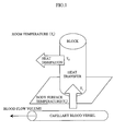
- Fig. 1 shows a model for the description of the transfer of heat from the body surface to a solid block having a certain heat capacity when the block is brought into contact with the body surface for a certain time and then separated.
- the block is made of resin such as plastic or vinyl chloride. (For more detail, it is necessary to mention about the biocompatible material e.g. ABS which has a medical degree. It is required to use such material for medial device generally.)
- the blood flow volume can be estimated by monitoring mainly the chronological variation of the temperature T 2 (of a point on the spatially separated block). The details will be described later.
- the temperatures T 1 and T 2 at the two points of the block are equal to the room temperature T r .
- the temperature T 1 swiftly rises due to the transfer of heat from the skin as the block contacts the body surface, and it approaches the body-surface temperature T s .
- the temperature T 2 is less than the temperature T 1 as the heat conducted through the block is dissipated from the block surface, and it rises more gradually than the temperature T 1 .
- the chronological variation of the temperatures T 1 and T 2 depends on the amount of heat transferred from the body surface to the block, which in turn depends on the blood flow volume in the capillary blood vessels under the skin.
- the heat transfer coefficient from the capillary blood vessels to the surrounding cell tissues is given as a function of the blood flow volume. Accordingly, by monitoring the temperature changes in the T 1 and T 2 chronologically, and thus measuring the amount of heat transfer from the body surface to the block, the amount of heat transfer from the capillary blood vessels to the cell tissues can be estimated, so that the blood flow volume can be estimated.
- the cross-sectional area with respect to the flow direction is known, it is possible to obtain the amount of heat flowing into or out from the substance per unit of time by multiplying the calculated heat flux by the cross-sectional area of the substance.
- the total amount of heat transferred from the heat source to the substance while the substance is in contact with the heat source can be calculated by multiplying the heat amount by the time during which the substance and the heat source are in contact.
- heat supplied from the heat source to a substance in contact therewith comprises a component which is lost due to heat release (radiation) from the substance surface, in addition to a component which forms the temperature distribution by heat conduction inside the substance. This is a non-negligible factor when estimating the total heat amount supplied from the heat source.
- the heat flux of the heat amount lost by the radiation (heat flux of radiation: q r (W/m 2 )) can be calculated as indicated by the equation below by obtaining chronological temperature variations of the substance in contact with the heat source together with the ambient temperature (room temperature represented by Tr) when the heat conductivity, density ⁇ (kg/m 3 ), specific heat c (J/kgK), volume V (m 3 ), surface area F (m 2 ) and the like of a substance are known.
- room temperature room temperature represented by Tr
- a measurement point is set at a position at a distance "x" from the origin.
- the value measured at the measurement point is expressed as T(K).
- the characters " ⁇ ” and “ ⁇ ” represent emissivity and Stefan-Boltzmann constant, respectively.
- the characters "T,” “t,” and “x” represent measured temperature, time, and a coordinate on the one-dimensional coordinate system.
- the character “ ⁇ ” on the right side of the equation represents heat conductivity (m 2 /s).
- the product (first term of the right side of the equation) of heat conductivity (physical property) and the value obtained by second-order differentiation of the measured temperature with respect to the position represents the heat flux on the assumption that the total heat amount supplied by heat conduction inside the substance reaches the measurement point "x" and the temperature distribution occurs.
- the second term of the right side of the equation represents the heat flux obtained from actual chronologically measured variations (time differentiation of the measured temperature). The difference between these heat fluxes is the heat flux released to the outside of the substance in the form of radiation.
- the heat amount Q total (W) transferred from the heat source in contact with the substance can be calculated by measuring the temperature distribution of the substance having known physical properties and chronological temperature variations. Namely, the heat amount Q total (W) transferred from the heat source is obtained by multiplying the sum of the heat fluxes obtained from the above Fourier's law and Stefan-Boltzmann equation, by a cross-sectional area of the substance (area in contact with the heat source), as indicated by the following equation.
- Q total ⁇ q+q r ⁇ F
- Fig. 2 shows the chronological variation of the measured values of the temperature T 1 at the portion of the block in contact with the body surface and the temperature T 2 at the position on the block away from the body-surface contact position.
- Fig. 3 shows the chronological variation of the measured value of the temperature T 3 measured by a radiation temperature detector.
- the detector detects the temperature due to the radiation from the body surface, it is more sensitive to temperature changes than other sensors. Because radiation heat propagates as an electromagnetic wave, it can transmit temperature changes instantaneously.
- the time of start of contact t start between the block and the body surface, and the time of end of contact t end can be detected by changes in the temperature T 3 .
- a temperature threshold value is set as shown in Fig. 3.
- the contact start time t start is when the temperature threshold value is exceeded.
- the contact end time t end is when the temperature T 3 drops below the threshold.
- the temperature threshold is set at 32°C, for example.
- T b 1 + c ⁇ exp(- a ⁇ t ) + d
- T temperature
- t time
- the measured value can be approximated by determining factors a, b, c, and d by the non-linear least-squares method.
- T is integrated between time t start and time t end to obtain a value S 1 .
- an integrated value S 2 is calculated from the T 2 measured value.
- a 5 /(t CONT ⁇ (S 1 - S 2 )) is designated as a parameter X 5 indicating the volume of blood flow, where a 5 is a proportionality coefficient.
- the measured amounts necessary for the determination of blood glucose concentration by the above-described model are the room temperature (ambient temperature), body surface temperature, temperature changes in the block brought into contact with the body surface, the temperature due to radiation from the body surface, and the absorbance of at least two wavelengths.
- Fig. 4 shows the relationships between the measured values provided by various sensors and the parameters derived therefrom.
- a block is brought into contact with the body surface, and chronological change in two kinds of temperatures T 1 and T 2 are measured by two temperature sensors provided at two locations of the block.
- a radiation temperature T 3 on the body surface and the room temperature T 4 are separately measured.
- Absorbance A 1 and A 2 are measured at at least two wavelengths related to the absorption of hemoglobin.
- the temperatures T 1 , T 2 , T 3 , and T 4 provide parameters related to the volume of blood flow.
- the temperature T 3 provides a parameter related to the amount of heat transferred by radiation.
- the temperatures T 3 and T 4 provide parameters related to the amount of heat transferred by convection.
- the absorbance A 1 provides a parameter related to the hemoglobin concentration.
- the absorbance A 1 and A 2 provide parameters related to the hemoglobin oxygen saturation.
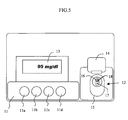
- Fig. 5 shows a top plan view of the non-invasive blood sugar level measuring apparatus according to the invention. While in this example the skin on the ball of the finger tip is used as the body surface, other parts of the body surface may be used.
- an operation unit 11 On the top surface of the apparatus are provided an operation unit 11, a measuring unit 12 where the finger to be measured is to be placed, and a display unit 13 for displaying the state of the apparatus, measured values, and so on.
- the operation unit 11 includes four push buttons 11a to 11d for operating the apparatus.
- the measuring unit 12 has a cover 14 which, when opened (as shown), reveals a finger rest 15 with an oval periphery.
- the finger rest 15 accommodates an opening end 16 of a radiation temperature sensor, a contact temperature sensor 17, and an optical sensor unit 18.
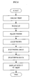
- Fig. 6 shows the procedure for operating the apparatus.
- an indication "Warming up” is displayed on the LCD display while the electronic circuits in the apparatus are being warmed up.
- a check program is activated to automatically check the electric circuits.
- an indication "Place your finger” appears on the LCD display.
- the LCD display begins counting down. When the countdown is over, an indication "Put your finger away” appears on the LCD display.
- the LCD display indicates “Processing data.” Thereafter, the display shows the blood sugar level, which is then stored in an IC card together with the date and time.
- the apparatus displays a message "Place your finger” on the LCD display, thus indicating that the apparatus is ready for the next cycle of measurement.
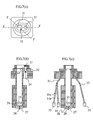
- Fig. 7 shows the measuring unit in detail.
- Fig. 7(a) is a top plan view
- (b) is a cross section along line X-X of (a)
- (c) is a cross section along line Y-Y of (a).
- a bar-shaped heat-conducting member 22 made of material such as polyvinylchloride whose heat conductivity is lower than that of the plate 21 is thermally connected to the plate 21 and extends into the apparatus.
- the temperature sensors include a thermistor 23 for measuring the temperature of the plate 21 and acting as an adjacent temperature detector with respect to the measured object.
- thermistor 24 for measuring the temperature of the heat-conducting member away from the plate 21 by a certain distance and acting as an indirect temperature detector with respect to the measured object.
- the plate 21, heat-conducting member 22, and thermistors 23 and 24 constitute a heat transfer amount measuring unit.
- a certain amount of heat supplied from a heat source such as a finger is externally released and consumed, in addition to heat used to form the temperature distribution inside the contact part (particularly the plate 21) and the heat-conducting member 22 and heat lost from the contact part as radiation heat. Furthermore, there is a possibility that heat is supplied from a source other than the heat source, that is, the measured object. In such cases, heat to be measured is not measured, or heat that should not be measured is measured. As a result, a measurement error is caused, and thus there is a possibility that an error would occur in calculating a final blood glucose concentration.
- the apparatus is configured so as to strengthen the thermal connection by employing a structure such that: the plate 21 is formed of gold or a metal having a high heat conductivity equal to gold; and the thermistors 23 and 24 are connected to the heat-conducting member 22 with an adhesive having a high heat conductivity, or implanted in the heat-conducting member 22.
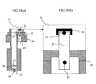
- Fig. 10 shows a detailed view (a) of the measuring unit and a detailed, magnified view (b) of peripheral structure 37 of the heat transfer amount measuring unit thereof.
- the heat transfer amount measuring unit has a structure such that the plate 21 and thermistors 23 and 24 are mounted on the bar-shaped (herein, for example, a round bar) heat-conducting member 22, and the heat-conducting member 22 is mounted in contact with a supporting column portion 36 constituting the blood sugar level measuring apparatus.
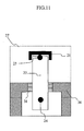
- Fig. 11 shows an embodiment wherein a heat insulation structure or a structure for reducing heat conductivity is applied to the heat transfer amount measuring unit described in Fig. 10(b).
- a heat insulator 38 is concentrically disposed with respect to the round bar-shaped heat-conducting member 22 to be mounted on the supporting column portion 36 through the heat insulator.
- fiber materials or foaming materials having voids formed therein, or micro dust layer materials may be employed.
- the heat conductivity thereof may be from about 0.0005 W/mK to about 0.002 W/mK.
- the heat conductivity thereof may be from about 0.005 W/mK to about 0.02 W/mK.
- the heat conductivity thereof may be from about 0.0005 W/mK to about 0.009 W/mK.
- the materials used as the heat insulator desirably have a heat conductivity from about 0.0005 W/mK to about 0.02 W/mK.
- the heat conductivity of the portion where such heat insulator is used can be substantially reduced in light of the facts that the heat conductivity of air is approximately 0.025 W/mK and that the heat conductivity is several hundred mW/mK when a resin material such as a plastic is used as a material for main portions of the apparatus except portions replaceable with a heat insulator and various detectors.
- the heat exchange between the heat-conducting member 22 and the supporting column portion 36 can be substantially reduced.
- the heat insulator is practically in contact with the heat-conducting member 22 and the supporting column portion 36, the heat insulator used herein has a lower heat conductivity than either of these items.
- Fig. 18 shows a detailed view (a) of the measuring unit, a detailed, magnified view (b) of one embodiment of the heat transfer amount measuring unit and a peripheral portion 42 thereof, and a detailed, magnified view (c) of another embodiment of the heat transfer amount measuring unit and the peripheral portion 42 thereof.
- portions formed of the insulating material are colored black.
- the properties of the insulating material are the same as above. While the upper supporting column member 43, the supporting column portion 36, and the lower supporting column member 44 are all formed of the insulating material in Fig. 18(b), the upper supporting column member 43 and the supporting column portion 36 are formed of the insulating material in Fig. 18(c). In addition, the side portion of the heat-conducting member 22 may be covered with the insulating material. Such structure enables a larger reduction in the heat exchange from the heat-conducting member 22 to the other constituent portions of the apparatus adjacent to the heat-conducting member 22 through the insulating material portion in the same manner the structure of Fig. 11.
- the total heat amount to be transferred between substances or within a substance is a value obtained by multiplying the heat flux (W/m 2 ) defined by the temperature difference and heat conductivity by the contact area F (m 2 ).
- W/m 2 the heat flux
- F the contact area
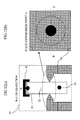
- Fig. 12 shows an embodiment wherein the cross section of a contact portion of the supporting column portion 36, shown in Fig. 10(b), with the heat-conducting member 22 has a triangular shape so that the supporting column portion 36 has a line contact with the heat-conducting member 22.
- Fig. 12(a) is a detailed, magnified view of a peripheral structure 37 of the heat transfer amount measuring unit and a cross-section along line B-C of Fig. 12(b).
- Fig. 12(b) shows a state viewed from point A of Fig. 12(a).
- the total heat amount to be transferred between substances or within a substance is obtained by multiplying the heat flux (W/m 2 ) defined by a temperature difference and heat conductivity by a contact area F (m 2 ). According to the present method, the heat flux is not decreased but the contact area is deceased, so consequently the heat to be transferred is reduced.
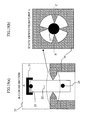
- Fig. 19 shows an embodiment wherein a contact portion of the supporting column portion 36 with the heat-conducting member 22 is formed to be a projecting portion for point contact.
- Fig. 19(a) is a detailed, magnified view of the peripheral structure 37 of the heat transfer amount measuring unit and a cross-section along line B-C of Fig. 19(b).
- Fig. 19(b) shows a state viewed from point A of Fig. 19(a).
- Fig. 20 shows an embodiment wherein a contact portion of the supporting column portion 36 with the heat-conducting member 22 is formed to be a projecting portion for line contact in a longitudinal direction of the heat-conducting member.
- Fig. 20(a) is a detailed, magnified view of the peripheral structure 37 of the heat transfer amount measuring unit and a cross-section along line B-C of Fig. 20(b).
- Fig. 20(b) shows a state viewed from point A of Fig. 20(a).
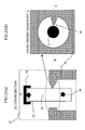
- Fig. 21 shows an embodiment wherein a contact portion of the supporting column portion 36 with the heat-conducting member 22 is formed to be a projecting portion for point contact and the projecting portion is fixed at an adhesion site 45 of the heat-conducting member 22 with an adhesive agent.
- Fig. 21(a) is a detailed, magnified view of the peripheral configuration 37 of the heat transfer amount measuring unit and a cross-section along line B-C of Fig. 21(b).
- Fig. 21(b) shows a state viewed from point A of Fig. 21(a).
- Fig. 22 shows an embodiment wherein a contact portion of the supporting column portion 36 with the heat-conducting member 22 is formed to project from the supporting column portion 36 and to have a connection portion 46, and a holding portion 47 is formed to cover a circumferential surface of the heat-conducting member and to support it.
- Fig. 22(a) is a detailed, magnified view of the peripheral structure 37 of the heat transfer amount measuring unit and a cross-section along line B-C of Fig. 22(b).
- Fig. 22(b) shows a state viewed from point A of Fig. 22(a).
- the contact portion of the supporting column portion 36 with the heat-conducting member 22, namely the end portion is formed to have a smaller diameter at a position adjacent to the heat-conducting member than the diameters of the other portions of the supporting column portion 36, or at least the maximum diameter thereof.
- the connection and holding portions are formed of a material having a lower heat conductivity than the supporting column portion.
- Figs. 13 to 17 The insulation effect when the insulation structure is employed will be described by referring to Figs. 13 to 17.
- a finger as heat source is in contact with the heat transfer amount measuring unit as shown above
- the temperature distributions of the heat-conducting member 22 or supporting column portion 36 constituting the heat transfer amount measuring unit that are created are measured with a temperature measurement means such as a thermograph.
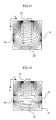
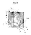
- Figs. 13, 14, and 16 show the results of temperature distribution measurement with an isotherm, while the position of the heat-conducting member 22 or the supporting column portion 36 is indicated by a dotted line.
- the finger as heat source is in contact with a position represented as a reference numeral 39.
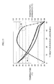
- left vertical axes indicate measured temperatures and right vertical axes indicate temperature difference.
- an axis to be used for reading plots thereof is indicated by an arrow.
- Fig. 13 shows a temperature distribution within the heat-conducting member 22 and of the surrounding space thereof when the heat-conducting member is present in the air, not in contact with any substance, and located at a substantial distance from the supporting column portion 36, while the heat-conducting member 22 is indicated by the dotted line.
- Heat-source-like points 40 and 41 at right and left sides are placed corresponding to the position of the supporting column portion 36, and the figure shows that the supporting column portion has a higher temperature than the surrounding air (ambience).
- Heat is conducted from a finger contact point at the upper part of the heat-conducting member 22, namely the contact point of the heat source to the inside of the heat-conducting member 22, and the temperature is almost equidistantly distributed. It is found that the heat flows evenly through the inside of the heat-conducting member 22 without the loss of the heat flux from the finger as heat source by avoiding contact with the supporting column member.
- Fig. 14 shows a temperature distribution within the heat-conducting member 22 and of the supporting column portion 36, and the surrounding space of the heat-conducting member 22, without the application of the present invention, while the heat-conducting member 22 and the contact portion of the supporting column portion 36 with the heat-conducting member are indicated by dotted lines. It is found that the intervals of the isotherm are quite different between the upper and lower connection portions between the heat-conducting member 22 and the supporting column portion 36. This indicates that the heat flux derived from the finger as heat source is varied. In other words, it indicates that the heat flux supplied from the heat source is affected at the supporting column portion 36 in contact therewith and that the heat flows towards the supporting column portion.
- Fig. 15 shows a comparison between the temperature distributions in the Y axis direction from the center of the heat-conducting member 22 in the X axis direction in the state of Fig. 13 and the state wherein the heat-conducting member 22 comes into contact with the supporting column portion 36 without the application of the present invention as described in Fig. 14.
- the temperatures measured in the state of Fig. 13 and the state of Fig. 14 and the measured temperature difference between their individual states are indicated by square plots, rhombic plots, and triangular plots, respectively.
- temperature measurement errors of up to 1.8°C are found in the case of the state of Fig. 14 with respect to the state of Fig. 13.
- Fig. 16 shows a temperature distribution of the inside of the heat-conducting member 22 and the supporting column portion 36 and the surrounding space of the heat-conducting member 22 when an insulator 38 is provided between the heat-conducting member 22 and the supporting column portion 36, where the heat-conducting member 22, the supporting column portion 36, and the insulator 38 are indicated by dotted lines.
- Fig. 17 shows the comparison between the temperature distributions in the Y axis direction from the center of the heat-conducting member 22 in the X axis direction in the state of Fig. 13 and the state of Fig. 16.
- the temperatures measured in the state of Fig. 13, the state of Fig. 16, and the measured temperature difference between individual states of them are indicated by square plots, rhombic plots, and triangular plots, respectively.
- An infrared lens 25 is disposed inside the apparatus at such a position that the measured object (ball of the finger) placed on the finger rest 15 can be seen through the lens.
- a pyroelectric detector 27 below the infrared lens 25 is disposed a pyroelectric detector 27 via an infrared radiation-transmitting window 26.
- Another thermistor 28 is disposed near the pyroelectric detector 27.
- the temperature sensor portion of the measuring unit has four temperature sensors, and they measure four kinds of temperatures as follows:
- the optical sensor unit 18 measures the hemoglobin concentration and the hemoglobin oxygen saturation necessary for the determination of the oxygen supply volume. In order to measure the hemoglobin concentration and the hemoglobin oxygen saturation, absorption must be measured at at least two wavelengths.
- Fig. 7(c) shows a configuration for carrying out the two-wavelength measurement using two light sources 33 and 34 and one detector 35.
- the optical sensor unit 18 includes the ends of two optical fibers 31 and 32.
- the optical fiber 31 is for optical irradiation, and the optical fiber 32 is for receiving light.
- the optical fiber 31 connects to branch fibers 31a and 31b that are provided with light-emitting diodes 33 and 34 at the respective ends thereof.
- the other end of the light-receiving optical fiber 32 is provided with a photodiode 35.
- the light-emitting diode 33 emits light with a wavelength of 810 nm, while the light-emitting diode 34 emits light with a wavelength of 950 nm.
- the wavelength 810 nm is the equal absorption wavelength at which the molar absorbance coefficient of the oxy-hemoglobin is equal to that of the deoxy-hemoglobin.
- the wavelength 950 nm is the wavelength at which the difference between the molar absorbance coefficient of the oxy-hemoglobin and that of the deoxy-hemoglobin is large.
- the two light-emitting diodes 33 and 34 emit light in a time-sharing manner such that the finger of the subject is irradiated with the light emitted by the light-emitting diodes 33 and 34 via the irradiating optical fiber 31.
- the light shone on the finger is reflected by the skin, enters the light-receiving optical fiber 32, and is eventually detected by the photodiode 35.
- Part of the light reflected by the skin of the finger penetrates the skin and enters into the tissues and is then absorbed by the hemoglobin in the blood flowing in the capillary blood vessels.
- the measurement data provided by the photodiode 35 has reflectance R, and the absorbance can be approximately calculated by log(1/R).
- the finger is thus irradiated with light with the wavelengths of 810 nm and 950 nm, and R is measured for each and also log(1/R) is calculated for each.
- absorption A 1 and A 2 for wavelengths 810 nm and 950 nm, respectively, are measured.
- absorption A 1 and A 2 are expressed by the following equations:
- a Hb (810 nm) and A Hb (950 nm), and A HbO2 (810 nm) and A HbO2 (950 nm) are the molar absorbance coefficients of the deoxy-hemoglobin and the oxy-hemoglobin, respectively, and are known at the respective wavelengths.
- the term a is a proportionality coefficient.
- the hemoglobin concentration and the hemoglobin oxygen saturation are measured by measuring absorbance at two wavelengths.
- absorbance may be measured at more than two wavelengths so that the influence of interfering components can be reduced and measurement accuracy can be improved.
- major interfering components include melanin pigment to determine skin color, bilirubin as a causative substance of jaundice symptom, and blood turbidity as a cause of hyperlipidemia.
- wavelength values described in this specification are the values most suitable to obtain individual absorbances of interest, such as to obtain absorbance at a wavelength where molar absorbance coefficients are equal, or to obtain peaks of absorbances. Therefore, wavelengths of roughly those described in the present specification, that is wavelengths of about 20 nm above or below the described wavelengths, can be used similarly for measurement.
- Fig. 8 shows the concept of how data is processed in the apparatus.
- the apparatus according to the present example is equipped with five sensors, namely thermistor 23, thermistor 24, pyroelectric detector 27, thermistor 28, and photodiode 35.
- the photodiode 35 measures absorption at wavelengths 810 nm and 950 nm.
- the apparatus is supplied with six kinds of measurement values.
- the temperature T 1 used in the determination of S 1 is 37°C and the temperature T 2 used in the determination of S 2 is measured at 24°C with the application of the above configurations
- the temperature T 2 without the application of the above structures may be measured at about 22°C.
- the values S 1 and S 2 are substantially proportional to the measured temperature although they are obtained by integration with respect to the time. These values are substituted into the parameter x 5 proportional to the blood flow volume and the proportionality coefficient a 5 is kept constant. Then, the above case is taken as an example wherein when T 1 is 37°C, T 2 with the application of the insulation structure or the structure for the reduction of the heat conductivity is 24°C and T 2 without the application the structure is 22°C. In the example, x 5 is calculated and compared as below.
- values S 1 and S 2 are products of individual measured temperatures and measured times (t count ) for simplicity.
- the measured temperature difference of 2°C between cases with and without the application of the structures is regarded as a measurement error, because when the structure is applied, it is confirmed that the measurement conditions are desired on the basis of the review of the above temperature distribution.
- normalized parameters are calculated from mean values and standard deviations of x i obtained by actual data pertaining to large numbers of able-bodied people and diabetic patients.
- the ROM stores, as a constituent element of the program necessary for the processing calculations, a function for determining glucose concentration C in particular.
- the function is defined as follows.
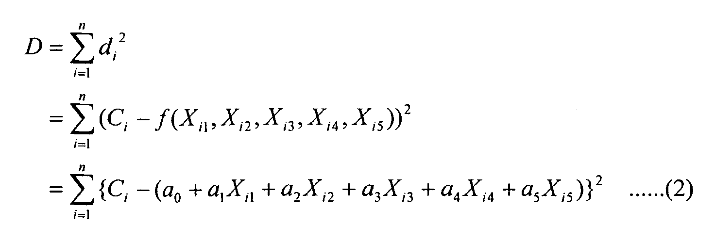
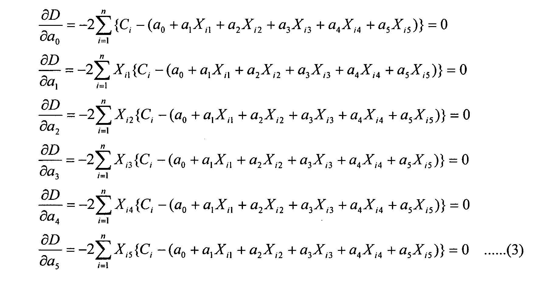
- the regression equation (1) indicating the relationship between the glucose concentration C and the normalized parameters X 1 , X 2 , X 3 , X 4 , and X 5 is formulated.
- Constant term a 0 is obtained by means of equation (4).
- the normalized parameters X 1 to X 5 obtained from the measured values are substituted into regression equation (1) to calculate the glucose concentration C.
- the coefficients in equation (1) are determined in advance based on large data obtained from able-bodied persons and diabetic patients, using the apparatus without the application of the above insulation structure or the structure for the reduction of the heat conductivity.
- the ROM in the microprocessor stores the following formula for the calculation of glucose concentration.
- C 99.4 + 18.3 ⁇ X 1 - 20.2 ⁇ X 2 - 23.7 ⁇ X 3 - 22.0 ⁇ X 4 - 29.8 ⁇ X 5
- the measurement by the enzymatic electrode method was conducted at the same time that the above examples were conducted.
- a blood sample was reacted with a reagent and the amount of resultant electrons was measured to determine glucose concentration.
- the glucose concentration for an able-bodied person was 89 mg/dl according to the enzymatic electrode method.
- the glucose concentration for the diabetic patient was measured according to the enzymatic electrode method in the same manner at the same time as the above example, and was found to be 238 mg/dl.
- FIG. 9 shows the plot of glucose concentration for a plurality of patients.
- the invention can provide a highly accurate non-invasive blood sugar level measuring apparatus and method.
Landscapes
- Health & Medical Sciences (AREA)
- Life Sciences & Earth Sciences (AREA)
- Physics & Mathematics (AREA)
- Engineering & Computer Science (AREA)
- Heart & Thoracic Surgery (AREA)
- Surgery (AREA)
- Emergency Medicine (AREA)
- Optics & Photonics (AREA)
- Combustion & Propulsion (AREA)
- Biophysics (AREA)
- Pathology (AREA)
- Biomedical Technology (AREA)
- Chemical & Material Sciences (AREA)
- Medical Informatics (AREA)
- Molecular Biology (AREA)
- General Physics & Mathematics (AREA)
- Animal Behavior & Ethology (AREA)
- General Health & Medical Sciences (AREA)
- Public Health (AREA)
- Veterinary Medicine (AREA)
- Measurement Of The Respiration, Hearing Ability, Form, And Blood Characteristics Of Living Organisms (AREA)
- Investigating Or Analysing Biological Materials (AREA)
- Measuring And Recording Apparatus For Diagnosis (AREA)
- Investigating Or Analysing Materials By Optical Means (AREA)
- Measuring Pulse, Heart Rate, Blood Pressure Or Blood Flow (AREA)
Abstract
Description




xi: parameter
SD(xi): standard deviation of the parameter




Claims (20)
- A blood sugar level measuring apparatus comprising:wherein the oxygen volume measuring unit comprises a blood flow volume measuring unit for obtaining information concerning the volume of blood flow and a heat transfer prevention means for preventing heat transfer to the blood flow volume measuring unit from the vicinity thereof.a heat amount measuring unit for measuring a plurality of temperatures derived from the body surface in order to obtain information used for calculating the amount of convective heat transfer and the amount of radiation heat transfer concerning the dissipation of heat from the body surface;an oxygen volume measuring unit for obtaining information concerning the volume of blood oxygen;a storage unit for storing the relationships between the individual parameters corresponding to the multiple temperatures and blood oxygen volume and blood sugar levels;a computing unit for converting the measurement values provided by the heat amount measuring unit and the oxygen volume measuring unit into parameters, and computing a blood sugar level by applying the parameters to the relationships stored in the storage unit; anda display unit for displaying the blood sugar level computed by the computing unit,
- The blood sugar level measuring apparatus according to claim 1, wherein the blood flow volume measuring unit comprises:a body-surface contact unit;an adjacent temperature detector disposed adjacent the body-surface contact unit;an indirect temperature detector for detecting the temperature at a position distanced away from the body-surface contact unit; anda heat-conducting member connecting the body-surface contact unit and the indirect temperature detector, whereinthe heat transfer prevention means prevents heat transfer to the heat-conducting member.
- The blood sugar level measuring apparatus according to claim 1, further comprising at least one supporting column member for installing the blood flow volume measuring unit,
wherein the heat transfer prevention means is a heat insulator disposed between the heat-conducting member and the supporting column member and the heat insulator has a smaller heat conductivity than the supporting column member. - The blood sugar level measuring apparatus according to claim 3, wherein the heat insulator is formed of a material having the properties of any of a fiber material, a foaming material, or a micro dust layer material.
- The blood sugar level measuring apparatus according to claim 3, wherein the heat insulator has a heat conductivity of 0.0005 W/mK to 0.02 W/mK.
- The blood sugar level measuring apparatus according to claim 1, further comprising at least one supporting column member for installing the blood flow volume measuring unit, wherein the heat transfer prevention means is an end part of the supporting column member which is adjacent to the heat-conducting member and has a smaller diameter at a position adjacent to the heat-conducting member than the maximum diameter of the supporting column member.
- The blood sugar level measuring apparatus according to claim 6, wherein the end part has point contact with the heat-conducting member.
- The blood sugar level measuring apparatus according to claim 6, wherein the end part has linear contact with the heat-conducting member.
- The blood sugar level measuring apparatus according to claim 1, further comprising at least one supporting column member for installing the blood flow volume measuring unit, wherein
the heat transfer prevention means comprises a connecting part projecting from the supporting column member and a holding part which is connected to the connecting part and holds the heat-conducting member. - The blood sugar level measuring apparatus according to claim 1, wherein the oxygen volume measuring unit further comprises an optical measuring unit for obtaining blood hemoglobin concentration and hemoglobin oxygen saturation.
- The blood sugar level measuring apparatus according to claim 10, wherein the optical measuring unit comprises:a light source for generating light of at least two different wavelengths;an optical system for irradiating the body surface with light emitted by the light source; anda photodetector for detecting the light with which the body surface has been irradiated.
- The blood sugar level measuring apparatus according to claim 1, wherein the heat amount measuring unit comprises:an ambient temperature detector for measuring the ambient temperature; anda radiation temperature detector for measuring the radiation heat from the body surface.
- A non-invasive blood sugar level measuring apparatus comprising:a temperature measuring unit for measuring a plurality of temperatures from a body surface;a blood flow volume measuring unit for obtaining information concerning the volume of blood flow based on the results of measurement by the temperature measuring unit;an oxygen volume measuring unit for determining the volume of blood oxygen based on the result of measurement by the blood flow volume measuring unit;a storage unit for storing the relationships between individual parameters corresponding to the multiple temperatures, the volume of blood oxygen and the volume of blood flow, and blood sugar levels;a computing unit for converting the measurement values provided by the temperature measuring unit, the blood flow volume measuring unit and the oxygen volume measuring unit into parameters, and then applying the parameters to the relationships stored in the storage unit in order to compute a blood sugar level; anda display unit for displaying the blood sugar level computed by the computing unit, whereinthe blood flow volume measuring unit has a heat transfer prevention means for preventing heat transfer to the blood flow volume measuring unit from the vicinity thereof.
- A blood sugar level measuring apparatus comprising:an ambient temperature measuring unit for measuring the ambient temperature;a body-surface contact unit to be brought into contact with a body surface;a radiation heat detector for measuring the radiation heat from the body surface;a heat-conducting member disposed in contact with the body-surface contact unit;a heat insulator disposed in contact with the heat-conducting member;a contact part for covering an open end of the heat-conducting member in contact with the body-surface contact unit;an adjacent temperature detector for detecting the temperature of the contact part;an indirect temperature detector disposed adjacent the heat-conducting member and away from the body-surface contact unit for detecting the temperature at a position distanced away from the body-surface contact unit;a light source for irradiating the body-surface contact unit with light of at least two different wavelengths;a photodetector for detecting the light with which the body surface has been irradiated;a converting unit for converting the outputs from the adjacent temperature detector, the indirect temperature detector, the ambient temperature measuring unit, the radiation heat detector, and the photodetector into individual parameters;a storage unit for storing the relationships between the parameters and blood sugar levels;a computing unit for computing a blood sugar level by applying the individual outputs to the relationships stored in the storage unit; anda display unit for displaying the blood sugar level produced from the computing unit.
- The blood sugar level measuring apparatus according to claim 14, further comprising at least one supporting column member for installing the heat-conducting member, wherein the heat insulator has a lower heat conductivity than the supporting column member.
- The blood sugar level measuring apparatus according to claim 14, further comprising at least one supporting column member for installing the heat-conducting member, wherein the heat insulator is disposed between the heat-conducting member and the supporting column member.
- A blood sugar level measuring apparatus comprising:an ambient temperature measuring unit for measuring the ambient temperature;a body-surface contact unit to be brought into contact with a body surface;a radiation heat detector for measuring the radiation heat from the body surface;a heat-conducting member disposed in contact with the body-surface contact unit;a supporting column member which supports the heat-conducting member and has a smaller diameter at a site adjacent to the heat-conducting member than the maximum diameter of the supporting column member;a contact part for covering an open end of the heat-conducting member in contact with the body-surface contact unit;an adjacent temperature detector for detecting the temperature of the contact part;an indirect temperature detector disposed adjacent the heat-conducting member and away from the body-surface contact unit for detecting the temperature at a position distanced away from the body-surface contact unit;a light source for irradiating the body-surface contact unit with light of at least two different wavelengths;a photodetector for detecting the light with which the body surface has been irradiated;a converting unit for converting the outputs of the adjacent temperature detector, the indirect temperature detector, the ambient temperature measuring unit, the radiation heat detector, and the photodetector into individual parameters;a storage unit for storing the relationships between the parameters and blood sugar levels;a computing unit for computing a blood sugar level by applying the individual outputs to the relationships stored in the storage unit; anda display unit for displaying the blood sugar level produced from the computing unit.
- The blood sugar level measuring apparatus according to claim 17, wherein the end part has a smaller diameter at a site adjacent to the heat-conducting member than the other parts of the supporting column member.
- The blood sugar level measuring apparatus according to claim 17, wherein the end part is in contact with the heat-conducting member through linear contact.
- The blood sugar level measuring apparatus according to claim 17, wherein the end part is in contact with the heat-conducting member through point contact.
Applications Claiming Priority (2)
| Application Number | Priority Date | Filing Date | Title |
|---|---|---|---|
| JP2003195455A JP3566278B1 (en) | 2003-07-11 | 2003-07-11 | Blood glucose meter |
| JP2003195455 | 2003-07-11 |
Publications (2)
| Publication Number | Publication Date |
|---|---|
| EP1495714A1 true EP1495714A1 (en) | 2005-01-12 |
| EP1495714B1 EP1495714B1 (en) | 2007-06-13 |
Family
ID=33028445
Family Applications (1)
| Application Number | Title | Priority Date | Filing Date |
|---|---|---|---|
| EP20030019213 Expired - Lifetime EP1495714B1 (en) | 2003-07-11 | 2003-08-25 | Blood sugar level measuring apparatus |
Country Status (5)
| Country | Link |
|---|---|
| US (1) | US7120478B2 (en) |
| EP (1) | EP1495714B1 (en) |
| JP (1) | JP3566278B1 (en) |
| CN (1) | CN1576846A (en) |
| DE (1) | DE60314388T2 (en) |
Cited By (5)
| Publication number | Priority date | Publication date | Assignee | Title |
|---|---|---|---|---|
| EP1595493A1 (en) * | 2004-05-10 | 2005-11-16 | Hitachi, Ltd. | Blood sugar level measuring apparatus |
| EP1642524A1 (en) * | 2004-09-29 | 2006-04-05 | Hitachi, Ltd. | Method and apparatus for measuring blood sugar levels |
| US8092386B1 (en) | 2006-12-22 | 2012-01-10 | Pacesetter, Inc. | Method and implantable system for blood-glucose concentration monitoring |
| US8630692B2 (en) | 2009-04-30 | 2014-01-14 | Pacesetter, Inc. | Method and implantable system for blood-glucose concentration monitoring using parallel methodologies |
| WO2022020734A1 (en) * | 2020-07-24 | 2022-01-27 | A.D. Integrity Applications Ltd. | Device for non-invasively measuring glucose concentration |
Families Citing this family (14)
| Publication number | Priority date | Publication date | Assignee | Title |
|---|---|---|---|---|
| JP3590053B1 (en) * | 2004-02-24 | 2004-11-17 | 株式会社日立製作所 | Blood glucose measurement device |
| JP2006115947A (en) * | 2004-10-19 | 2006-05-11 | Hitachi Ltd | Blood glucose level measuring device |
| EP1937138A2 (en) * | 2005-09-20 | 2008-07-02 | Philips Intellectual Property & Standards GmbH | Medical device |
| TW200801768A (en) * | 2006-06-02 | 2008-01-01 | Altek Corp | An image acquisition device |
| JP5191104B2 (en) * | 2006-06-22 | 2013-04-24 | ナノグレイ株式会社 | Radiation applied measurement method, radiation applied measurement device, and heat insulating material for radiation applied measurement device |
| US20080043809A1 (en) * | 2006-08-18 | 2008-02-21 | Herbert Curtis B | Thermometer |
| EP2203725A4 (en) * | 2007-10-15 | 2011-04-20 | Bayer Healthcare Llc | Method and assembly for determining the temperature of a test sensor |
| JP5216709B2 (en) * | 2009-07-23 | 2013-06-19 | 株式会社日立メディアエレクトロニクス | Blood glucose level measuring device |
| US8489164B2 (en) | 2010-10-27 | 2013-07-16 | Medtronic, Inc. | Monitoring of tissue hemoglobin concentration |
| JP2014077664A (en) * | 2012-10-09 | 2014-05-01 | Ricoh Co Ltd | Glossiness evaluation method and glossiness evaluation device |
| KR102335739B1 (en) | 2014-12-19 | 2021-12-06 | 삼성전자주식회사 | Apparatus and method for measuring a blood glucose in a noninvasive manner |
| WO2016120870A1 (en) * | 2015-01-26 | 2016-08-04 | Nir Geva | Systems and methods for vital signs monitoring with ear piece |
| KR101798109B1 (en) | 2016-06-03 | 2017-11-17 | 주식회사 아이센스 | Blood Glucose Tester |
| KR102727114B1 (en) * | 2019-02-01 | 2024-11-06 | 현대자동차주식회사 | Non-invasive optical internal substance detector |
Citations (4)
| Publication number | Priority date | Publication date | Assignee | Title |
|---|---|---|---|---|
| US4333803A (en) * | 1980-10-03 | 1982-06-08 | Aluminum Company Of America | Method and apparatus for controlling the heat balance in aluminum reduction cells |
| US4802489A (en) * | 1986-07-29 | 1989-02-07 | Jerusalem College Of Technology | Method for carrying out blood flow measurements and a probe therefor |
| US5924996A (en) * | 1994-07-06 | 1999-07-20 | Ok Kyung Cho | Process and device for detecting the exchange of heat between the human body and the invented device and its correlation to the glucose concentration in human blood |
| WO2001028414A2 (en) * | 1999-10-20 | 2001-04-26 | Kaufmann-Kim, Yun-Oak | Device for carrying out the non-invasive determination of the concentration of constituents in the blood |
Family Cites Families (30)
| Publication number | Priority date | Publication date | Assignee | Title |
|---|---|---|---|---|
| US4306569A (en) * | 1979-10-10 | 1981-12-22 | Institute Of Critical Care Medicine | Apparatus and method for assessing the condition of critically ill patients |
| CA1240052A (en) * | 1984-11-30 | 1988-08-02 | Motoji Shiozumi | Method of and apparatus for determining glossinesses of surface of body |
| JPH0771945A (en) | 1992-08-07 | 1995-03-17 | Kao Corp | Surface texture measuring method and apparatus |
| IL107396A (en) * | 1992-11-09 | 1997-02-18 | Boehringer Mannheim Gmbh | Method and apparatus for analytical determination of glucose in a biological matrix |
| JPH06317566A (en) | 1993-05-06 | 1994-11-15 | Hitachi Ltd | Photoacoustic analysis method and apparatus and blood component measuring apparatus using the same |
| DE4342105A1 (en) * | 1993-12-12 | 1995-06-14 | Cho Ok Kyung | Method and device for the non-invasive determination of the concentration of glucose in parts of the human body, in particular in human blood, by performing highly accurate temperature measurements of the human body |
| JP3859746B2 (en) | 1995-05-31 | 2006-12-20 | 株式会社島津製作所 | Optical measuring device for light absorber |
| US5743262A (en) * | 1995-06-07 | 1998-04-28 | Masimo Corporation | Blood glucose monitoring system |
| US6240306B1 (en) * | 1995-08-09 | 2001-05-29 | Rio Grande Medical Technologies, Inc. | Method and apparatus for non-invasive blood analyte measurement with fluid compartment equilibration |
| US5769784A (en) * | 1995-11-27 | 1998-06-23 | Hill-Rom, Inc. | Skin perfusion evaluation apparatus and method |
| US5803915A (en) | 1995-12-07 | 1998-09-08 | Ohmeda Inc. | System for detection of probe dislodgement |
| US5725480A (en) * | 1996-03-06 | 1998-03-10 | Abbott Laboratories | Non-invasive calibration and categorization of individuals for subsequent non-invasive detection of biological compounds |
| JPH1033512A (en) | 1996-07-26 | 1998-02-10 | Hitachi Ltd | Non-invasive biochemical measurement device |
| US5732711A (en) * | 1996-08-27 | 1998-03-31 | Air-Shields, Inc. | Body function measuring apparatus |
| JPH10108857A (en) | 1996-10-04 | 1998-04-28 | Hitachi Ltd | Biochemical measurement device |
| US6269314B1 (en) * | 1997-08-19 | 2001-07-31 | Omron Corporation | Blood sugar measuring device |
| JPH11155840A (en) | 1997-11-27 | 1999-06-15 | Matsushita Electric Ind Co Ltd | Blood glucose meter |
| JPH11230901A (en) | 1998-02-09 | 1999-08-27 | Shimadzu Corp | Light reflection measurement device |
| JPH11318872A (en) | 1998-05-18 | 1999-11-24 | Matsushita Electric Ind Co Ltd | Blood glucose meter with diabetes judgment function |
| JP2000037355A (en) * | 1998-07-24 | 2000-02-08 | Fuji Photo Film Co Ltd | Method for measuring glucose concentration and apparatus therefor |
| JP2000074829A (en) | 1998-09-02 | 2000-03-14 | Mitsui Chemicals Inc | Glucose sensor |
| US6353226B1 (en) | 1998-11-23 | 2002-03-05 | Abbott Laboratories | Non-invasive sensor capable of determining optical parameters in a sample having multiple layers |
| US6615061B1 (en) * | 1998-11-23 | 2003-09-02 | Abbott Laboratories | Optical sensor having a selectable sampling distance for determination of analytes |
| AU754677B2 (en) | 1999-01-22 | 2002-11-21 | Instrumentation Metrics, Inc. | System and method for noninvasive blood analyte measurements |
| US6280381B1 (en) * | 1999-07-22 | 2001-08-28 | Instrumentation Metrics, Inc. | Intelligent system for noninvasive blood analyte prediction |
| JP2000258343A (en) | 1999-03-12 | 2000-09-22 | Mitsui Mining & Smelting Co Ltd | Blood glucose measurement method and apparatus |
| EP1223854A1 (en) | 1999-10-15 | 2002-07-24 | Abbott Laboratories | Method for modulating light penetration depth in tissue and diagnostic applications using same |
| US6595929B2 (en) | 2001-03-30 | 2003-07-22 | Bodymedia, Inc. | System for monitoring health, wellness and fitness having a method and apparatus for improved measurement of heat flow |
| WO2003010510A2 (en) | 2001-07-25 | 2003-02-06 | Argose, Inc. | Adjunct quantitative system and method for non-invasive measurement of in vivo analytes |
| US6923571B2 (en) | 2002-02-08 | 2005-08-02 | Compliance Laboratories, L.L.C. | Temperature-based sensing device for detecting presence of body part |
-
2003
- 2003-07-11 JP JP2003195455A patent/JP3566278B1/en not_active Expired - Fee Related
- 2003-08-25 EP EP20030019213 patent/EP1495714B1/en not_active Expired - Lifetime
- 2003-08-25 DE DE2003614388 patent/DE60314388T2/en not_active Expired - Fee Related
- 2003-08-28 US US10/649,689 patent/US7120478B2/en not_active Expired - Fee Related
- 2003-08-29 CN CNA03156304XA patent/CN1576846A/en active Pending
Patent Citations (4)
| Publication number | Priority date | Publication date | Assignee | Title |
|---|---|---|---|---|
| US4333803A (en) * | 1980-10-03 | 1982-06-08 | Aluminum Company Of America | Method and apparatus for controlling the heat balance in aluminum reduction cells |
| US4802489A (en) * | 1986-07-29 | 1989-02-07 | Jerusalem College Of Technology | Method for carrying out blood flow measurements and a probe therefor |
| US5924996A (en) * | 1994-07-06 | 1999-07-20 | Ok Kyung Cho | Process and device for detecting the exchange of heat between the human body and the invented device and its correlation to the glucose concentration in human blood |
| WO2001028414A2 (en) * | 1999-10-20 | 2001-04-26 | Kaufmann-Kim, Yun-Oak | Device for carrying out the non-invasive determination of the concentration of constituents in the blood |
Cited By (5)
| Publication number | Priority date | Publication date | Assignee | Title |
|---|---|---|---|---|
| EP1595493A1 (en) * | 2004-05-10 | 2005-11-16 | Hitachi, Ltd. | Blood sugar level measuring apparatus |
| EP1642524A1 (en) * | 2004-09-29 | 2006-04-05 | Hitachi, Ltd. | Method and apparatus for measuring blood sugar levels |
| US8092386B1 (en) | 2006-12-22 | 2012-01-10 | Pacesetter, Inc. | Method and implantable system for blood-glucose concentration monitoring |
| US8630692B2 (en) | 2009-04-30 | 2014-01-14 | Pacesetter, Inc. | Method and implantable system for blood-glucose concentration monitoring using parallel methodologies |
| WO2022020734A1 (en) * | 2020-07-24 | 2022-01-27 | A.D. Integrity Applications Ltd. | Device for non-invasively measuring glucose concentration |
Also Published As
| Publication number | Publication date |
|---|---|
| DE60314388D1 (en) | 2007-07-26 |
| CN1576846A (en) | 2005-02-09 |
| DE60314388T2 (en) | 2008-02-14 |
| US7120478B2 (en) | 2006-10-10 |
| JP3566278B1 (en) | 2004-09-15 |
| JP2005027821A (en) | 2005-02-03 |
| US20050010094A1 (en) | 2005-01-13 |
| EP1495714B1 (en) | 2007-06-13 |
Similar Documents
| Publication | Publication Date | Title |
|---|---|---|
| EP1484006B1 (en) | Blood sugar level measuring apparatus | |
| US7251514B2 (en) | Blood sugar level measuring apparatus | |
| US7215983B2 (en) | Blood sugar level measuring apparatus | |
| US7156810B2 (en) | Blood sugar level measuring method and apparatus | |
| EP1518493B1 (en) | Blood sugar level measuring method | |
| EP1563787A1 (en) | Blood sugar level measuring apparatus | |
| US7251517B2 (en) | Blood sugar level measuring apparatus | |
| US7251515B2 (en) | Blood sugar level measuring apparatus | |
| US7254427B2 (en) | Optical measurements apparatus and blood sugar level measuring apparatus using the same | |
| EP1495714B1 (en) | Blood sugar level measuring apparatus | |
| EP1568309A1 (en) | Blood sugar level measuring apparatus | |
| EP1649803A1 (en) | Blood sugar level measuring apparatus | |
| JP3884036B2 (en) | Blood glucose level measuring device | |
| EP1595493A1 (en) | Blood sugar level measuring apparatus | |
| EP1642524A1 (en) | Method and apparatus for measuring blood sugar levels | |
| EP1537822A1 (en) | Blood sugar level measuring apparatus | |
| JP3874743B2 (en) | Temperature measuring device | |
| US20060084853A1 (en) | Blood sugar level measuring apparatus |
Legal Events
| Date | Code | Title | Description |
|---|---|---|---|
| PUAI | Public reference made under article 153(3) epc to a published international application that has entered the european phase |
Free format text: ORIGINAL CODE: 0009012 |
|
| AK | Designated contracting states |
Kind code of ref document: A1 Designated state(s): AT BE BG CH CY CZ DE DK EE ES FI FR GB GR HU IE IT LI LU MC NL PT RO SE SI SK TR |
|
| AX | Request for extension of the european patent |
Extension state: AL LT LV MK |
|
| 17P | Request for examination filed |
Effective date: 20050202 |
|
| 17Q | First examination report despatched |
Effective date: 20050329 |
|
| AKX | Designation fees paid |
Designated state(s): DE FR GB |
|
| GRAP | Despatch of communication of intention to grant a patent |
Free format text: ORIGINAL CODE: EPIDOSNIGR1 |
|
| GRAS | Grant fee paid |
Free format text: ORIGINAL CODE: EPIDOSNIGR3 |
|
| GRAA | (expected) grant |
Free format text: ORIGINAL CODE: 0009210 |
|
| AK | Designated contracting states |
Kind code of ref document: B1 Designated state(s): DE FR GB |
|
| REG | Reference to a national code |
Ref country code: GB Ref legal event code: FG4D |
|
| REF | Corresponds to: |
Ref document number: 60314388 Country of ref document: DE Date of ref document: 20070726 Kind code of ref document: P |
|
| ET | Fr: translation filed | ||
| PLBE | No opposition filed within time limit |
Free format text: ORIGINAL CODE: 0009261 |
|
| STAA | Information on the status of an ep patent application or granted ep patent |
Free format text: STATUS: NO OPPOSITION FILED WITHIN TIME LIMIT |
|
| 26N | No opposition filed |
Effective date: 20080314 |
|
| PGFP | Annual fee paid to national office [announced via postgrant information from national office to epo] |
Ref country code: FR Payment date: 20080717 Year of fee payment: 6 |
|
| PGFP | Annual fee paid to national office [announced via postgrant information from national office to epo] |
Ref country code: GB Payment date: 20080718 Year of fee payment: 6 |
|
| PGFP | Annual fee paid to national office [announced via postgrant information from national office to epo] |
Ref country code: DE Payment date: 20081021 Year of fee payment: 6 |
|
| GBPC | Gb: european patent ceased through non-payment of renewal fee |
Effective date: 20090825 |
|
| REG | Reference to a national code |
Ref country code: FR Ref legal event code: ST Effective date: 20100430 |
|
| PG25 | Lapsed in a contracting state [announced via postgrant information from national office to epo] |
Ref country code: DE Free format text: LAPSE BECAUSE OF NON-PAYMENT OF DUE FEES Effective date: 20100302 Ref country code: FR Free format text: LAPSE BECAUSE OF NON-PAYMENT OF DUE FEES Effective date: 20090831 |
|
| PG25 | Lapsed in a contracting state [announced via postgrant information from national office to epo] |
Ref country code: GB Free format text: LAPSE BECAUSE OF NON-PAYMENT OF DUE FEES Effective date: 20090825 |