EP1495364B1 - A radiation sensitive recording plate with an orientation identifying marker and method of using same - Google Patents
A radiation sensitive recording plate with an orientation identifying marker and method of using same Download PDFInfo
- Publication number
- EP1495364B1 EP1495364B1 EP03719715A EP03719715A EP1495364B1 EP 1495364 B1 EP1495364 B1 EP 1495364B1 EP 03719715 A EP03719715 A EP 03719715A EP 03719715 A EP03719715 A EP 03719715A EP 1495364 B1 EP1495364 B1 EP 1495364B1
- Authority
- EP
- European Patent Office
- Prior art keywords
- plate
- image
- marker
- front side
- radiation
- Prior art date
- Legal status (The legal status is an assumption and is not a legal conclusion. Google has not performed a legal analysis and makes no representation as to the accuracy of the status listed.)
- Expired - Lifetime
Links
Images


Classifications
-
- G—PHYSICS
- G03—PHOTOGRAPHY; CINEMATOGRAPHY; ANALOGOUS TECHNIQUES USING WAVES OTHER THAN OPTICAL WAVES; ELECTROGRAPHY; HOLOGRAPHY
- G03B—APPARATUS OR ARRANGEMENTS FOR TAKING PHOTOGRAPHS OR FOR PROJECTING OR VIEWING THEM; APPARATUS OR ARRANGEMENTS EMPLOYING ANALOGOUS TECHNIQUES USING WAVES OTHER THAN OPTICAL WAVES; ACCESSORIES THEREFOR
- G03B42/00—Obtaining records using waves other than optical waves; Visualisation of such records by using optical means
- G03B42/02—Obtaining records using waves other than optical waves; Visualisation of such records by using optical means using X-rays
- G03B42/04—Holders for X-ray films
- G03B42/047—Holders for X-ray films provided with marking means
-
- G—PHYSICS
- G01—MEASURING; TESTING
- G01N—INVESTIGATING OR ANALYSING MATERIALS BY DETERMINING THEIR CHEMICAL OR PHYSICAL PROPERTIES
- G01N23/00—Investigating or analysing materials by the use of wave or particle radiation, e.g. X-rays or neutrons, not covered by groups G01N3/00 – G01N17/00, G01N21/00 or G01N22/00
- G01N23/02—Investigating or analysing materials by the use of wave or particle radiation, e.g. X-rays or neutrons, not covered by groups G01N3/00 – G01N17/00, G01N21/00 or G01N22/00 by transmitting the radiation through the material
- G01N23/04—Investigating or analysing materials by the use of wave or particle radiation, e.g. X-rays or neutrons, not covered by groups G01N3/00 – G01N17/00, G01N21/00 or G01N22/00 by transmitting the radiation through the material and forming images of the material
-
- G—PHYSICS
- G03—PHOTOGRAPHY; CINEMATOGRAPHY; ANALOGOUS TECHNIQUES USING WAVES OTHER THAN OPTICAL WAVES; ELECTROGRAPHY; HOLOGRAPHY
- G03C—PHOTOSENSITIVE MATERIALS FOR PHOTOGRAPHIC PURPOSES; PHOTOGRAPHIC PROCESSES, e.g. CINE, X-RAY, COLOUR, STEREO-PHOTOGRAPHIC PROCESSES; AUXILIARY PROCESSES IN PHOTOGRAPHY
- G03C11/00—Auxiliary processes in photography
- G03C11/02—Marking or applying text
-
- G—PHYSICS
- G03—PHOTOGRAPHY; CINEMATOGRAPHY; ANALOGOUS TECHNIQUES USING WAVES OTHER THAN OPTICAL WAVES; ELECTROGRAPHY; HOLOGRAPHY
- G03C—PHOTOSENSITIVE MATERIALS FOR PHOTOGRAPHIC PURPOSES; PHOTOGRAPHIC PROCESSES, e.g. CINE, X-RAY, COLOUR, STEREO-PHOTOGRAPHIC PROCESSES; AUXILIARY PROCESSES IN PHOTOGRAPHY
- G03C5/00—Photographic processes or agents therefor; Regeneration of such processing agents
- G03C5/16—X-ray, infrared, or ultraviolet ray processes
- G03C2005/168—X-ray material or process
Definitions
- This application relates generally to image processing. More specifically, the application relates to identifying image orientation. Yet more specifically, the application relates to identifying image orientation in medical and dental X-ray shadow-grams.
- the image seen by the viewer whether projected or viewed on the light box, will have a known defined correspondence with the orientation of the objects in the original scene. Moreover, even if orientation is lost, reorienting based on determining where the emulsion is will reestablish proper orientation.
- CCDs charge-coupled devices
- CCDs charge-coupled devices
- the cameras used to produce such images are physically constructed and arranged with a tens or lens mount in a fixed position relative to the detector, so that the direction from which the exposing radiation strikes the detector is always known.
- CCD sensors used in dental digital radiography also are physically constructed and arranged to produce a diagnostic image only when exposed from the proper direction. Such CCD sensors include a radiopaque element on the side away from the intended direction of exposure.
- dental or medical diagnostic image is a shadow-gram produced by placing a radiographic film on one side of the object to be imaged and a source of radiation to which the film is sensitive on a diametrically opposite side of the object to be imaged.
- the radiation for example X-radiation, casts a shadow of the object to be imaged on the film, thus revealing density variations within.the object whose shadow has been cast.
- the laterality i.e.
- radiographic film is usually held in an opaque cassette which not only prevent exposure to visible light, but also limits X-ray exposure to one side of the film, only.
- US Patent 5,123,040 describes an X-ray film cassette with a permanent marking means for identifying the front side of the radiographic film.
- the side of the cassette through which large format film, such as that used for medical X-ray applications, is exposed often includes radiopaque labels indicating various patient information, including patient name, date of exposure, side of the patient (e.g. left or right arm), etc., for example, which provide a clear indication embedded in the image of the side of the film from which the exposure was made.
- dental intraoral films are conventionally provided prepackaged in packets, which may be disposable and which are often flexible. Because intraoral films must be small enough to be positioned within the mouth, there is little room available for the types of labels described above.
- Patent CH 564943 discloses a pen for marking radiographic film, however there is no indication to the technician/dentist from which side of the mouth the radiation impinged.
- proper orientation is identified by a raised or embossed bump on the film and packet that points away from a radiopaque backing in the packet that prevents or limits inadvertent exposure from the wrong side.
- the bump which projects from the plane of the film in the direction from which the shadow is cast, is a permanent feature of the film and persists as marker of the orientation in the dimension perpendicular to the plane of the film, providing a method by which the viewer can identify the side of exposure. If an exposure is made from the wrong side, the resulting image is recognizably undiagnostic because of its degradation caused by the radiopaque backing contained within the packet.
- the radiopague backing typically a textured heavy metal foil, causes exposure from the wrong side to appear in the image as a textured pattern, while the embossed feature preserves and identifies the orientation information for the viewer.
- dental intraoral films are produced in a variety of generally rectangular standard sizes, with rounded corners. Also by convention, when prepared for viewing, they are grouped in an anatomical arrangement in a holder called a mount. Standard mounts hold films in one of two orientations only: with the longer dimension of the film in a horizontal orientation, henceforth in this application referred to as “landscape” orientation; and with the longer dimension of the film oriented vertically, henceforth referred to in this application as "portrait" orientation.
- the frame of reference for principal directions is based on the image plane, itself. Up shall be a direction generally from any point in the image toward a top of the edge of the image, while down is in an opposite direction. With the up direction oriented in a natural fashion for a viewer, left and right correspond to the viewer's left and right. Vertical corresponds to the direction of a line running up and down from any point in the image.
- Patent 4,625,325 describes a method which incorporates both conventional radiographic film and phosphor in the same process with radiopaque material.
- the device described patented therein includes a film packet, similar to the intraoral dental film packet described above.
- the device also incorporates a pocket for holding a plate which is inserted by the technician prior to the exposure of the film.
- the plate which is coated with a phosphor on the side facing the film and radiation source and which incorporates radiopaque material on the opposite side, is positioned adjacent to the film in the packet.
- the plate is an image amplifier.
- the film is exposed both by X-rays impinging directly on the film and by the phosphorescence emitted by the plate phosphor stimulated by the same X-rays.
- Those X-rays which have passed both the film and the phosphor are absorbed by the radiopaque backing, thereby limiting tissue exposure downstream of the recording surfaces.
- the packet, film and plate are held by a jig in a position such that the film and plate can only be exposed from one side.
- the phosphor only functions as an amplifier to provide improved signal-to-noise ratio and to lower the radiation dose per exposure.
- the phosphor film does not function as a storage phosphor holding a latent image, and is not scanned to produce a diagnostic digital image. Furthermore, no issues of image orientation ambiguity from a digital electronic image result from the process, because the image is recorded on conventional radiographic film, as before.
- Radiosensitive storage phosphor plates have recently started displacing conventional radiographic emulsion film for recording medical and dental images. Advantages including superior sensitivity, lack of dependence on toxic chemical processing fluids, relative insensitivity to ambient light, reusability, and the ease of digital data storage and transmission all stimulate the growth of this technology.
- the orientation of the image produced by film technology was identified unambiguously by the presence of a three-dimensional object, namely the bump protruding from the film surface toward the object casting the shadow, providing a permanent and absolute reference in a dimension perpendicular to the plane of the film.
- the other two dimensions, superior-inferior and anterior-posterior are inferred from the anatomical structures in the image.
- the images produced by existing phosphor plate technologies are stored and displayed as two-dimensional views without a complete, definite, and permanent indicator of the direction of exposure or of viewing.
- Incomplete references or markers, as discussed below are incorporated into the existing systems; however, none of the systems are unambiguous, permanent, or complete by virtue of their design.
- radiosensitive plates are sensitive to a specific, diagnostic radiation type, e.g., X-rays, they are substantially insensitive to visible light for the purposes of registering an image. They can be handled in ordinary room light, absent the usual cassette until the time of the exposure. They are, for sanitary and other purposes such as reducing wear and tear on the phosphor, inserted into radiolucent plastic film sleeves before each use.
- the plates are also reusable to produce multiple images over a period of time. Erasure, by prolonged exposure to intense visible light, and repackaging in the disposable radiolucent plastic film sleeves is done by a technician at the point of use, rather than at the point of manufacture.
- a scanner through laser illumination, stimulates the phosphor to emit light in an amount which depends on the amount of prior exposure to X-rays, and which in turn is registered as data signal.
- phosphor-based digital radiology systems use plates having a polymer sheet substrate supporting a pastel-colored phosphor layer applied to one surface of the substrate. The other surface of the substrate appears black.
- the side of the plate which is intended by the manufacturer as the preferred side to be read, e.g., by the scanner, to produce the diagnostic image shall be referred to as the "front side", while the opposite side of the plate and sensitive layer shall be referred to as the "back side” henceforth.
- the side of the plate that is generally intended as the side to be scanned (“front side") is also the side on which the sensitive layer is nearer the surface of the plate and is visible, thereby available for excitation by the scanning mechanism.
- the sensitive layer e.g., phosphor
- the sensitive layer e.g., phosphor
- the sensitive layer e.g., phosphor
- the "front side” only, it can be exposed and register a latent image from either side, and in some commercial systems equally well.
- the shadow recorded by the sensitive layer e.g., phosphor
- the recorded latent image as well as the visible image resulting from its scan are ambiguous with respect to their laterality.
- bilaterally symmetric structures e.g., left or right jaw
- mirror images result, which can be easily confused since they are not uniquely oriented.
- DigoraTM available from Soredex
- phosphor plates incorporate a slightly radiopaque layer on the "back side" of the plate, which reduces patient irradiation by rays that pass through the plate and into the patient.
- the radiopacity of the backing is featureless, but the backing degrades an image exposed by irradiation from the "back side.”
- markers are distinctively shaped, either a lower case letter "a” opaquely printed over the "front side” of the phosphor or a small open circle evident as an absence of the phosphor in a localized area, respectively. These markers are incorporated at the time of fabrication of the plates by the manufacturer and are constructed in such a way as to always be read from the phosphor by the scanner in a constant fashion independent of any exposure variables. The result of the presence of a marker produced by either of the above variants, i.e.
- Scan-X and Denoptics, in fabrication is a diminution, or absence, of phosphorescence from the area of the plate so altered, during scanning. This relative lack of signal is reflected in the visible scan image as a distinct shape corresponding to the shape and the location of the marker on the phosphor plate,
- any features of such a marker that are either asymmetric or placed asymmetrically with respect to a vertical axis of symmetry of the plate, or both, become represented by similarly asymmetric features in the image of the plate following a scan. Furthermore, this marker image becomes reversed with respect to its laterality either in respect to its asymmetric location or its internal asymmetry as a result of software horizontal reflection of the scanned image. As the placement of the source of the radiation during the exposure has no influence over the appearance of the image of such marker, this marker is well suited as an indicator of any reversal of laterality of the entire image following the completion of the scan.
- US Patent 6354737 discloses the display of a digital orientation mark rather than the embedding of a marker in the plate.
- FIG. 1 illustrates generally how a dental X-ray plate can be used to produce images, X-ray shadowgrams, of a patient's lower jaw and teeth.
- the particular physiological structure is illustrative of the symmetry problem discussed above. However, the problem occurs in connection with many physiological structures as a result of the inherent symmetry present in most biological systems, particularly humans and animals.
- the configuration of FIG. 1 is now described as it relates to conventional digital dental X-ray plates. Later, in the DETAILED DESCRIPTION, the configuration of FIG. 1 is referenced as it relates to aspects of the invention, which may be practiced in this configuration, as well as other suitable configurations.
- the anatomical structure illustrated in FIG. 1 is a human lower jaw, i.e., a human mandible 101, having a set of teeth 102 set therein.
- a human lower jaw i.e., a human mandible 101
- teeth 102 are part of a living patient's body, covered with the soft tissues, etc.
- This particular patient has a diagnostically significant condition, e.g., an abscess, denoted by filled circle 103.
- a dental technician, dentist or other has placed a conventional digital dental X-ray plate 104 in the patient's mouth in a position suitable for capturing a shadowgram of three of the patient's posterior teeth 105 on either side of the patient's mouth.
- FIGS. 2, 3, 4 and 5 are now described, with reference back to FIG 1 , as required.
- FIGS. 2, 3, 4 and 5 illustrate four images that can be produced using a conventional digital X-ray plate exposed from each of two sides, using each of two differently located sources, e.g., positioned at SOURCE L and SOURCE R.
- the reference conventional commercial plate has an open circle mark on the "front side" of the plate, in one corner, an open circle 201 appears in each of the images.
- Images produced by source, SOURCE L include images 205 of posterior teeth 105 and images produced by source, SOURCE R, include both images 205 of posterior teeth 105 and an image 203 of diagnostically significant condition 103.
- the open circle is present on the "front side" of the plate and is intended to direct the technician, dentist or other to face that side of the plate toward the exposure source. However, such a consistent usage is not guaranteed.
- the reflection of the image within this system can occur through one of two modes.
- the first mode involves casting the shadow, i.e., registering the image, onto the sensitive layer, e.g., phosphor, from one side of the plate, e.g., "back side", and reading it off the opposite aspect of the sensitive layer, e.g., "front side”. Only one instance of this mode may occur per image.
- This mode of reflection shall henceforth be referred to as "pre-exposure" reflection in this application.
- the second mode involves the use of an image processing software tool which reflects right-for-left any selected image. The number of instances of this mode of reflection is not theoretically limited. This mode of reflection shall henceforth be referred to as "software" reflection in this application.
- Rotation has two distinct modes.
- the first mode is a physical rotation of the plate, together with its markers, relative to the object to be imaged prior to exposure involved in changing the orientation from "landscape” to "portrait", and if continued, back to "landscape".
- This mode of rotation shall be referred to henceforth in this application as the "pre-exposure” mode of rotation.
- the second mode of rotation can occur several ways. After exposure, the plates, being small, unattached objects are free to be moved and become randomized in orientation. These plates are later removed from their sleeves and arbitrarily rotated as to fit into a plate holder mechanism of the scanner, the constraint at this stage being that the "front side" must face the sensor.
- the operator uses the image processor to align the images in proper superior-inferior orientation by rotating them.
- This software-mediated rotation is limited to multiples of ninety degrees and is the mechanism through which correct "landscape” and “portrait” orientation as well as superior-inferior relationship is achieved as needed. All three of the rotations given above maintain the relationship between the location of the marker and the details of the shadow-gram. They also preserve laterality.
- the several mechanisms of rotation comprising the second mode of rotation occur after the sensitive layer is exposed and will henceforth in this application be referred to as "post-exposure" mode of rotation. When a "post-exposure” rotation results in a 180 degree rotation, the resulting transformation is equivalent to a reflection of the entire recorded image through a point located at the intersection of the long and the short axes of symmetry of the plate.
- the two modes of reflection and two modes of rotation comprise the universe of orientation transformations allowed by the laws of physics and by the graphic functions included in the software of the image processors typically provided with digital radiography systems.
- a marker 3811 shall be placed in the lower right corner, as viewed from the "front side", of a plate in a "landscape” orientation. In FIG.
- images 3801, 3802, 3803, 3804, 3805, 3806, 3807 and 3808 within the same row are related to their neighboring images by one ninety-degree "post-exposure" rotation for each step.
- images within the same column are related by a "software" reflection through a vertical plane perpendicular to that of the plate.
- FIG. 3 is the image read from the "front side of the plate 104, when the plate so oriented is exposed by an X-ray at the location designated SOURCE R.
- the dentist can use image processing software to reorient the image horizontally flipping the image, as shown in FIG. 2 .
- Mark 201 is transposed from the right to the left, side of the image.
- the same plate 104 oriented the same way, but exposed from an X-ray source at the location designated SOURCE L, when read from the sensitive side of the plate 104, produces the image shown in FIG. 5 .
- the image of FIG. 4 can be inadvertently produced by manipulation of the image processing software to horizontally flip the image of FIG. 4 . Since FIGS. 2 and 4, and FIGS.
- condition 103 does not produce any externally observable symptoms, the X-ray image may be the only evidence upon which the dentist can rely for determining the location to treat.
- An ambiguity is introduced into the record that cannot be resolved without another exposure of the patient to radiation.
- Digital plate technology in its current form does not assure that the orientation of the image can be ascertained. Current technology instead relies on the statistical likelihood that the technician will expose the film correctly vast majority of the time. However, no unambiguous marker of the exposure orientation exists within the image. The following four examples illustrate the problem of a lack of an internal reference:
- FIGS. 6, 7, 8 and 9 are similar to FIGS. 2, 3, 4 and 5 , respectively, except for the initial orientation of the plate.
- These images are produced by a plate 104 oriented with an open circle, and consequently the sensitive side of the plate 104 oriented toward the X-ray source located at the position SOURCE L, but in the top left corner of the plate as viewed from the direction of the X-ray source located at the position SOURCE L.
- FIGS. 10, 11, 12 and 13 represent images produced by a plate 104 oriented with an open circle, and consequently the sensitive side of the plate 104 oriented toward the X-ray source located at the position SOURCE R, but in the bottom right corner of the plate as viewed from the direction of the X-ray source located at the position SOURCE R.
- FIG. 10 shows the image produced by SOURCE R, in which the open circle 201 is in the lower right corner.
- FIG. 11 can be inadvertently produced by a horizontal flip of the image of FIG. 10 using image processing software.
- FIG. 12 shows the result of exposing the plate using SOURCE L. In order to view the image in an orientation expected by the dentist, the image of FIG. 12 can be horizontally flipped to produce the image of FIG. 13 .
- FIGS. 10 and 12 are inherently indistinguishable, as are FIGS. 11 and 13 .
- FIGS. 14, 15, 16 and 17 The analysis of FIGS. 14, 15, 16 and 17 is similar to FIGS. 10, 11, 12 and 13 , respectively, except for the initial orientation of the plate. These images are produced by a plate 104 oriented with the open circle, and consequently the sensitive side of the plate 104 oriented toward the X-ray source located at the position SOURCE R, but in the top left corner of the plate as viewed from the direction of the X-ray source located at the position SOURCE R.
- a radiation-recording plate being constructed and arranged to form an image upon exposure from both a front side and a back side.
- the plate includes a marker detectable in the image after exposure and indicative of which of the front side and the back side the plate is exposed from.
- the marker may comprise a medium opaque to the radiation coating a region that does not interfere with reading the image when the plate is exposed from either side.
- the plate may be sensitive to X-radiation, and the medium may comprise one of a heavy element, an alloy including a heavy element, a compound including a heavy element or a salt of a heavy element.
- the medium could be one of Pb, Sn, Bi, I and Ba.
- the medium could be a heavy metal suspended in a binder applied to the region.
- the marker may have asymmetry about at least one axis.
- the marker may have horizontal asymmetry about a vertical axis relative to a normal image orientation, or the marker may have vertical asymmetry about a horizontal axis relative to a normal image orientation.
- the marker may further comprise a back side marker whose appearance in an image on the plate indicates exposure from the back side.
- the plate may have a layer sensitive to the radiation that is readable only from the front side, the back side marker further comprising at least one of a material that enhances reading the sensitive layer and a material that attenuates reading of the sensitive layer.
- a back side marker may further comprise at least one of a material that enhances exposure of the plate in a defined region and a material that attenuates exposure of the plate in the defined region.
- the back side marker may further comprise one of a heavy element, an alloy including a heavy element, a compound including a heavy element or a salt of a heavy element.
- the medium may be one of Pb, Sn, Bi, I and Ba.
- the plate may further comprise a front side marker whose appearance in an image on the plate indicates exposure from the front side.
- This plate may further have a layer sensitive to the radiation that is readable at least from the front side, the front side marker further comprising at least one of a void defined in the layer sensitive to the radiation, a material that enhances a signal returned in the area of the marker when reading the sensitive layer and a material that attenuates the signal returned in the area of the marker when reading the sensitive layer.
- the plate may be readable only from the front side by exciting the layer sensitive to the radiation with an excitation wavelength to generate a return signal at a return signal wavelength, the front side marker functionally opaque to at least one of the excitation signal wavelength and the return signal wavelength.
- the front side marker may further comprise one of a heavy element, an alloy including a heavy element, a compound including a heavy element or a salt of a heavy element.
- the medium may be one of Pb, Sn, Bi, I and Ba.
- the front side marker may further comprise a void defined in the layer sensitive to the radiation.
- the marker may have asymmetry about at least one axis and the marker further comprising a front side marker and a back side marker.
- the marker can have either horizontal asymmetry about a vertical axis or vertical asymmetry about a horizontal axis, relative to a normal image orientation.
- the front side marker may further comprise: a region defined to have a shape of an arrow pointed in a first direction when viewed from the front side.
- the back side marker may further comprise: a region defined to have a shape of an arrow pointed in a second direction different from the first direction when viewed from the front side.
- the back side marker can be positioned so as to obscure the front side marker when the plate is exposed from the back side and read from the front side.
- the plate may include another sensitive layer, wherein the back side marker is disposed between the sensitive layer and the other sensitive layer, and the plate further comprising another front side marker relative to the other sensitive layer.
- a method of identifying a side from which a radiation-recording plate has been exposed to radiation may comprise: incorporating in the plate, in a position that substantially does not interfere with an image area of the plate, a marker whose appearance in the image identifies which side the plate is exposed from; exposing the plate to the radiation; and observing the image for the identification of the side of the plate exposed.
- the method may further comprise: arranging the marker to indicate a rotational orientation of the plate; and observing the image for the indication of the rotational orientation of the plate.
- the method may yet further comprise observing the image using image processing software, the image processing software recognizing the marker and reorienting an image of the plate to have a clinically expected orientation.
- the method may yet further comprise: storing with the image an indication of whether the image has been reoriented by an odd number of times.
- the method may also comprise: substituting for the marker a replacement marker indicative of the software having processed the image; storing the image with the replacement marker.
- This method may also further comprise: storing with the image an indication of whether the image has been reoriented by an odd number of times.
- a method of making a radiation sensitive plate having at least one radiation sensitive layer may comprise: providing a film sensitive to the radiation on a first side of the radiation sensitive plate; and applying a suspension of a heavy metal in a binder to a region of a second side of the radiation sensitive layer.
- exposure of one side of a radiosensitive plate produces one indicator pattern in the image, while exposure of the other side of the radiosensitive plate produces a different indicator pattern in the image.
- the indicator pattern recorded on the radiosensitive plate becomes a permanent part of a data pattern recorded by the particular exposure.
- the indicator pattern may blanket the image or may be localized.
- It may render an image exposed through a substrate of the plate unusable, or may only minimally degrade image quality, or may be located so as not to degrade the quality of the image or data set in any way, for example by being small and located outside of a primary image forming area, such as in a corner of a rectangular plate.
- the means for forming the indicator pattern is a permanent part of the plate, put there at the time of manufacture, no single or repetitive operator act is required to mark plates with their direction of exposure, no protocol to ensure exposure from a particular side of a plate is required, unless an indicator of a type rendering the image unusable when exposed from a "wrong side" is used, and the indication of the direction of exposure is unambiguously embedded in any data set produced from such a plate. No special protocol or specification of protective sleeves is required for image orientation purposes, either, unless an indicator of a type rendering the image unusable when exposed from a "wrong side" is used.
- the indicator pattern can further be used to help identify laterality, i.e., "handedness," of an image.
- Preservation of the laterality of an image may be important because the symmetry inherent in the human body and most higher animal forms makes distinguishing between certain structures, such as a patient's left incisor and the patient's right incisor, difficult independently, i.e. without other sources of identification.
- laterality is fully defined by the direction of exposure and the structure depicted. This is so because the radiation source for intraoral dental X-rays is always located outside the patient's mouth and the sensitized plate is always located within the patient's mouth.
- a “front side” marker is one that produces a mark in an image on a plate exposed from the "front side", i.e., the side from which the plate is read, while a “back side” marker is one that produces a mark in an image on a plate exposed from the "back side” and subsequently read from the "front side”.
- the marker patterns can be produced by materials having suitable patterns placed intermediate the plate sensitive layer and the source of exposing radiation. These patterns can alternatively be produced by affecting the excitation and recording the resultant phosphorescence of the phosphor during the scan process, for example, by perforating the phosphor layer or by obscuring it.
- materials can, using any suitable process, be coated, printed, painted, laminated, sublimated, bonded, riveted, etc. onto the plate surfaces during the fabrication process.
- the materials can be selected to partially or wholly block or intensify, e.g. by use of different phosphor, the radiation reaching the plate in the area covered.
- a common material that blocks X-radiation, and can be usefully applied to plates in laminated form, in paints or in inks is lead.
- Other heavy metals or other heavy elements can also be used, in various forms, e.g., foils, grains, etc. of lead, tin, bismuth, barium, etc.
- heavy metals and heavy elements generally include any element from the fourth row of the periodic table and heavier.
- a dental plate including a plastic substrate onto which is coated a storage phosphor material sensitive to dental X-rays.
- the plates are produced in large sheets or continuous webs and then die-cut into their final size and shape.
- a plate such as just described, readable from one side, i.e., the "front side” has an indicator pattern-forming material, i.e., a marker, incorporated into such plate on the opposite side of the plane of the sensitive layer from which such plate is read.
- a marker i.e., a marker
- a mark is printed on the "back side", in one corner thereof.
- the mark is printed using a lead impregnated paint, or other suitable material.
- Other suitable constructions are described in greater detail, below.
- the resulting image When exposed from the "front side” of the plate, the resulting image includes no mark. However, when exposed from the "back side” of the plate, an unexposed mark is formed in that portion of the image corresponding to the corner of the plate on which the mark is printed.
- the image produced, including the mark can take the form of any of the images of FIGS. 2-33 .
- the mark need not have any special shape because the information desired can be simply derived from the presence or absence in the image of the mark.
- Images produced by exposing the plate from one side or the other are distinguishable in the same manner as described below in connection with FIGS. 18, 19 , 20 and 21 , for example. According to this embodiment, only a "back side” marker is required in contrast to conventional media which use only a "front side” marker.
- both a "front side” marker and a “back side” marker may be present.
- different patterns of indicator-forming material may be applied to opposite sides of a plate readable from one side.
- the "front side” marker may be one or more perforations in the phosphor.
- Embodiments of the invention incorporating both a "front side” marker and a “back side” marker can fully indicate the orientation of a structure imaged, even when the position of the radiation source and the radiation sensitive plate relative to the structure is unknown.
- the direction of exposure of the plate is unambiguously recorded in the image without any intervention or special act by the operator.
- the cassette or sleeve in which the plate is placed during exposure can include a radiopaque mark on one or both sides, unambiguously indicating the proper orientation of the cassette or sleeve relative to some absolute reference such as the left side or front of the patient.
- FIGS. 18, 19 , 20 and 21 illustrate four images that can be produced using a digital X-ray plate according to this embodiment of aspects of the invention, exposed from each of two sides, using each of two differently located sources, e.g., positioned at SOURCE L and SOURCE R.
- This embodiment has an open circle mark on the X-ray sensitive side of the plate, in one corner, and a filled circle mark on the other side of the plate, in this case in the same corner. In using this embodiment, attention need not be paid to which side faces the source because, as explained below, different marks appear on the image produced, depending on the side from which the plate is exposed.
- FIGS. 18, 19 , 20 and 21 Suppose, for the purpose of analyzing the images in FIGS. 18, 19 , 20 and 21 , that the technician, dentist or other exposing this patient's digital dental X-ray plate 104 has oriented the open circle, and consequently the sensitive side of the plate 104, toward the X-ray source located at the position SOURCE L, and in the lower right corner of the plate 104 as viewed from the direction of the X-ray source located at the position SOURCE L.
- the filled circle is on the opposite side of the plate 104, in the same corner as the open circle.
- FIG. 19 is the image read from the sensitive side of the plate 104, when the plate so oriented is exposed by an X-ray source at the location designated SOURCE R.
- FIG. 21 The same plate 104, oriented the same way, but exposed from an X-ray source at the location designated SOURCE L, when read from the sensitive side of the plate 104, produces the image shown in FIG. 21 .
- the image of FIG. 20 can be inadvertently produced by manipulation of the image processing software to horizontally flip the image of FIG. 21 .
- FIG. 21 must be the correct orientation because the open mark is located, as described above, in the lower-right corner of the plate 104. Since FIGS. 18 and 21 are clearly and unambiguously the correctly oriented images, the technician, dentist or other person reading the images knows with certainty that the condition 203 is on the patient's right side.
- FIGS. 22 , 23, 24 and 25 illustrate four images that can be produced using a digital X-ray plate according to this embodiment of aspects of the invention, exposed from each of two sides, using each of two differently located sources, e.g., positioned at SOURCE L and SOURCE R.
- This embodiment has an open circle mark on the X-ray sensitive side of the plate, in one corner, and a filled circle mark on the other side of the plate, in this case in the same corner.
- the marks are located in a top corner, rather than a bottom corner, as explained below. In using this embodiment, attention need not be paid to which side faces the source because, as explained below, different marks appear on the image produced, depending on the side from which the plate is exposed.
- FIGS. 22 , 23, 24 and 25 Suppose, for the purpose of analyzing the images in FIGS. 22 , 23, 24 and 25 , that the technician, dentist or other exposing this patient's digital dental X-ray plate 104 has oriented the open circle, and consequently the sensitive side of the plate 104, toward the X-ray source located at the position SOURCE L, and in the upper left corner of the plate 104 as viewed from the direction of the X-ray source located at the position SOURCE L.
- the filled circle is on the opposite side of the plate 104, in the same corner as the open circle.
- FIG. 23 is the image read from the sensitive side of the plate 104, when the plate so oriented is exposed by an X-ray source at the location designated SOURCE R.
- FIG. 22 represents the correct orientation of the image exposed through the back of the plate 104.
- FIG. 25 The image of FIG. 24 can be inadvertently produced by manipulation of the image processing software to horizontally flip the image of FIG. 25 .
- FIG. 25 must be the correct orientation because the open mark is located, as described above, in the lower-right corner of the plate 104. Since FIGS. 22 and 23 are clearly and unambiguously the correctly oriented images, the technician, dentist or other person reading the images knows with certainty that the condition 103 is on the patient's right side.
- FIGS. 26, 27, 28 and 29 illustrate four images that can be produced using a digital X-ray plate according to this embodiment of aspects of the invention, exposed from each of two sides, using each of two differently located sources, e.g., positioned at SOURCE L and SOURCE R.
- This embodiment has an open circle mark on the X-ray sensitive side of the plate, in one corner, and a filled circle mark on the other side of the plate, in this case in the same corner. In using this embodiment, attention need not be paid to which side faces the source because, as explained below, different marks appear on the image produced, depending on the side from which the plate is exposed.
- FIGS. 26, 27, 28 and 29 Suppose, for the purpose of analyzing the images in FIGS. 26, 27, 28 and 29 , that the technician, dentist or other exposing this patient's digital dental X-ray plate 104 has oriented the open circle, and consequently the sensitive side of the plate 104, toward the X-ray source located at the position SOURCE R, and in the lower right corner of the plate 104 as viewed from the direction of the X-ray source located at the position SOURCE R.
- the filled circle is on the opposite side of the plate 104, in the same corner as the open circle.
- FIG. 26 is the image read from the sensitive side of the plate 104, when the plate so oriented is exposed by an X-ray source at the location designated SOURCE R.
- the same plate 104 oriented the same way, but exposed from an X-ray source at the location designated SOURCE L, when read from the sensitive side of the plate 104, produces the image shown in FIG. 28 .
- the image of FIG. 29 can be produced by manipulation of the image processing software to horizontally flip the image of FIG. 28 , so as to locate the closed circle 1801 in the lower left corner of the image, as expected for an image produced by exposing the plate 104 from the "back side" of the plate. It is known that FIG. 29 must be the correct orientation because the closed mark is located, as described above, in the lower-left corner of the plate 104. Since FIGS. 26 and 29 are clearly and unambiguously the correctly oriented images, the technician, dentist or other person reading the images knows with certainty that the condition 103 is on the patient's right side.
- FIGS. 30, 31, 32 and 33 illustrate four images that can be produced using a digital X-ray plate according to this embodiment of aspects of the invention, exposed from each of two sides, using each of two differently located sources, e.g., positioned at SOURCE L and SOURCE R.
- This embodiment has an open circle mark on the X-ray sensitive side of the plate, in one corner, and a filled circle mark on the other side of the plate, in this case in the same corner.
- the marks are located in a top corner, rather than a bottom corner, as explained below. In using this embodiment, attention need not be paid to which side faces the source because, as explained below, different marks appear on the image produced, depending on the side from which the plate is exposed.
- FIGS. 30, 31, 32 and 33 Suppose, for the purpose of analyzing the images in FIGS. 30, 31, 32 and 33 , that the technician, dentist or other exposing this patient's digital dental X-ray plate 104 has oriented the open circle, and consequently the sensitive side of the plate 104, toward the X-ray source located at the position SOURCE R, and in the upper left corner of the plate 104 as viewed from the direction of the X-ray source located at the position SOURCE R.
- the filled circle is on the opposite side of the plate 104, in the same corner as the open circle.
- FIG. 30 is the image read from the sensitive side of the plate 104, when the plate so oriented is exposed by an X-ray source at the location designated SOURCE R.
- the same plate 104 oriented the same way, but exposed from an X-ray source at the location designated SOURCE L, when read from the sensitive side of the plate 104, produces the image shown in FIG. 32 .
- the image of FIG. 33 can be produced by manipulation of the image processing software to horizontally flip the image of FIG. 32 , so as to locate the closed circle 1801 in the upper right corner of the image, as expected for an image produced by exposing the plate 104 from the "back side" of the plate. It is known that FIG. 33 must be the correct orientation because the closed mark is located, as described above, in the lower-left corner of the plate 104. Since FIGS. 30 and 33 are clearly and unambiguously the correctly oriented images, the technician, dentist or other person reading the images knows with certainty that the condition 103 is on the patient's right side.
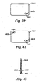
- the markers are asymmetric, are asymmetrically placed with respect to the plate surface axes of symmetry, and both "front side” and “back side” markers are employed.
- the markers 3901 and 3902 are made in the shape of arrows.
- markers 3901 and 3902 could be any suitable directional marker meeting the further requirements described in connection with this embodiment.
- the "front side” marker 3901 is a thin, short, horizontally directed arrow pointing at the right vertical edge of the plate at the lower edge of image 3900
- the "back side” marker 3902 is a solid arrow, also horizontally directed at the lower edge of a "landscape” oriented plate, but pointing away from the vertical edge of the plate of image 3900.
- the relationship between the markers 3901, 3902 produces an overlap between the image of the two markers.
- FIG. 40 In the interest of simplicity of the illustration only "landscape" orientation of the image need be discussed presently: By virtue of the relative ease in finding the superior-inferior orientation, it is for practical reasons nearly impossible to confuse two, intraoral dental images, as well as images of many other anatomical structures, which are related to each other by a rotation of ninety degrees because a horizontal image and a vertical image have teeth aligned either with the short or the long axis of the plate, an easily discriminated condition.
- FIG. 40 extends the method of analysis applied regarding FIG. 38 to the third embodiment of the invention.
- the two motions a 180 degree rotation around an axis perpendicular to the plane of the plate (or the image) at the intersection of its long and short axis, and a reflection through a vertical plane perpendicular to the plane of the image, are the four modes of manipulation which, singly or when combined, produce all allowed orientations of the image.
- the first mode is "pre-exposure” reflection of the plate, changing whether the plate is exposed from the "front side” or from the "back side". Depending on which initial reflection position a plate has been exposed in, one of group 4001 and 4002 will be the starting point of analysis.
- the second mode of manipulation is a physical rotation of the plate prior to exposure involved in changing the orientation from "portrait” to "landscape", and if continued, back to "landscape", and which changes the relationship between the location of the marker and details of the image produced by the shadow-gram.
- FIG. 38 and FIGs. 2 through 33 there exists equivalence between the two possible orientations attainable through this mode within the "landscape” orientation, and by extension also within the "portrait” orientation; therefore, further discussion of this manipulation will be deferred after stating that this rotation mode produces an effect on an asymmetric, or asymmetrically placed, marker which is equivalent to a reflection through a point located at the intersection of the plate's long and short axis of symmetry. Which initial exposure rotation has occurred determining whether the starting point for analysis of an image will be in the left column of images or the right column of images in FIG. 40 .
- the third mode a rotation of the plate after exposure, when mounted into the scanner or by software once the data has been captured, maintains the relationship between the location of the marker and the details of the shadow-gram. As discussed below, this mode is illustrated by movements between the left and right columns of FIG. 40 . This mode is referred to as "post-exposure" rotation.
- the fourth mode is software reflection of the image after capture. This manipulation is illustrated in FIG. 40 by vertical movement between rows, while remaining within the original group 4001 or 4002.
- a plate having "front side” markers and “back side” markers, exposed from an arbitrary side and then manipulated by image processing software will produce one of the images of FIG. 40 , as noted above. Analysis of those images is discussed below in connection with four hypothetical starting points 4003, 4004, 4007 and 4008.
- image 4003 An image scanned from a plate exposed in the conventionally “correct” orientation, that is, with the "front side” marker facing the source of radiation and at the lower edge is shown in image 4003.
- Software manipulations by rotation or reflection can produce any of images 4004, 4005, or 4006 in group 4001.
- the thin, "front side” marker arrow is at the lower edge facing right when the image 4002 is correctly oriented.
- the plate is exposed from the "back side", with the "back side” marker in the lower edge.
- image 4007 with the "back side” marker on the lower right, facing left is produced. Because this image was subject to a pre-exposure reflection, the scanned image 4007 is produced.
- a software reflection produces the correct image 4009.
- images 4008 and 4010 could also be produced by software manipulation, observe that "correct” image 4009 has the thick, "back side” marker arrow at the lower edge facing right.
- the plate is exposed from the "back side” after being rotated so that the "back side” marker is at the upper edge, producing scanned image 4008.
- it is manipulated using software to reflect horizontally the image 4008, to produce image 4010.
- the corrected image 4010 has the thick, "back side” marker arrow at the upper edge facing left.
- a simple rule can be derived from the four foregoing hypothetical using aspects of the third embodiment, whereby any image produced using the embodiment can be quickly and accurately oriented correctly for viewing.
- any marker arrow at the top edge of the image should point left, any marker arrow at the bottom edge of the image should point right.
- the image must, using software, be reflected horizontally to achieve correct orientation if the rule is not met initially.
- markers 4101, 4103, and 4104 are used in the following manner.
- the relationship between markers 4101, 4103, and 4104 is similar to that described in connection with markers 3901 and 3902 of the third embodiment.
- a second set of markers 4102, 4104 bearing a similar relationship is located at the point of reflection of the first set through a line passing perpendicularly through the center of the face of the plate.
- All possible images 4201-4208 generated by scanning such a plate exposed to a radiation source form the "front side" and from the "back side” are shown in corresponding positions to those of FIG. 40 .
- the arrows associated with the properly oriented images all point to the right if they are in the lower half of the image and to the left if they are in the upper half of the image, making a rule stated above even easier to apply.
- Such design of the marker shape and location in the processed image facilitates not only accurate and unambiguous orientation but also further reduces the number of decisions that an operator must make in the process of arranging the images in the mount, thus reducing the time required for the operation.
- the other is present to even in this rare situation provide indication of the laterality of the image.
- the plate is fitted with two layers of sensitive material, each possessing a small "front side” marker and allowing the mechanism which converts the latent image into a visible diagnostic image to read the plate from either or both sides and producing a recognizable pattern of that marker in such a diagnostic image, and a different indicator-informing marker, housed between the two sensitive layers, capable of producing a recognizable patter, preferably the image of the "front side” marker as in the foregoing embodiment, readable from either of the sensitive layers if such material lies between a radiation source and that layer.
- FIGS. 44A and 44B An example of aspects of this embodiment is shown by the plate 4400 illustrated in FIGS. 44A and 44B .
- the "front side" marker set FIG. 44A is compromised of two pairs, one pair on each side, of two arrows 4401, arranged on the plate in the following manner: each arrow, lying along and near a long edge if the plate, originates near the midpoint of the nearest long edge, originates near the midpoint of the nearest long edge and points toward the right short edge if it is located near the lower edge, or toward the left short edge if lying near the upper long edge.
- the same arrangement of arrows is present on the reverse side of the plate.
- the two arrows reflect onto one another through the point of intersection 4402 of the long 4403 and the short 4404 axes of symmetry of the plate as represented in FIGS. 44A and 44 B .
- the resulting "front side” marker configuration is such that the two sides 4405 and 4406 of the plate are indistinguishable from one another through any manipulations that preserve the "landscape” or "portrait” orientation of the plate 4400, i.e. any 180 degree or multiple thereof, rotation about any of the principal axes 4403 and 4404 of symmetry or the point 4402 of symmetry.
- radiopaque medium deposits 4407 which can cast a shadow onto the phosphor on the other side of the plate opposite the source of radiation and the radiographed object.
- the above arrangement of airow-shaped -front side” markers 4401 and internal material 4407 compromising a "back side” marker any image of an object exposed from and read from the same side of the plate will have proper orientation, as always, as scanned, with the lower edge arrow 4401 pointing to the right and the "back side” marker 4407 shadow absent.
- any image 4501 of an object exposed from one side of the plate and read from the other will reveal the back side" marker image 4502, which will appear at the right side, i.e. the tail, of the lower arrow 4503 when diagnostic image has been properly oriented by the software.
- An image with the lower arrow ( FIG. 44 , 4401) pointing right in the absence of the "back side” marker shadow has also been properly oriented.
- an image (not shown) with a "back side” marker shadow present at the left end, i.e. the tail, of the "front side” marker would indicate an image in which right and left are reversed and requiring software reflection for proper orientation of the diagnostic image.
- similar analysis generates simple rules for proper image orientation.
- plates according to the various embodiments described produce images with distinctive markers permanently embedded in the image information.
- the distinctive markers can be recognized and acted upon by the dentist or technician viewing the images, or can be automatically recognized and acted upon by the image processing software used to view the images. More sophisticated software can first perform the superior/inferior orientation on its own, based on any suitable image processing rules, while less sophisticated software can rely on the operator to first perform the superior/inferior orientation. In order to effect automatic orientation recognition and reorientation, the image processing software would next search the known possible locations of the markers for those particular shapes corresponding to the markers. When one of those shapes is found in one of those possible locations of the markers, a rule for correctly orienting the image is then applied.
- the simple rule set forth above can easily be applied automatically by the software to bring each image immediately into its correct orientation.
- the software can also be written to replace a marker recognized within an image with one of its own. The substitution would help those using the images recognize that they have been processed and correctly oriented.
- the reflection process performed by the image processing software can modify the file by toggling a "reflection flag" indicative of whether the image has been reflected an odd or even number of times.
- the reflection flag can be embedded within the image file, can be stored in an independent file, can be part of the image file name, or stored in any other suitable location.
- the value of the reflection flag can represent one of two states. The reflection process and reflection flag would preferably satisfy the following conditions:
- the image processing system would display a correctly oriented image either if the "back side” marker were present and the reflection flag were indicating an odd number of reflection operations, or if the "back side” marker were absent and the reflection flag indicated an even (including zero) number of reflection operations.
- Plates embodying aspects of the invention can be manufactured by any suitable method.
- the mark to be produced can be of any arbitrary size relative to the size of the plates to be produced.
- placement of the mark can be synchronized with the locations from which the plates are cut, may be randomly placed relative to the locations from which the plates are cut, or may completely blanket the locations from which the plates are cut. Synchronization can be achieved by any suitable method, including those known in the printing arts for aligning printed elements and die cuts.
- a small, highly distinctive mark can be placed in a consistent, predetermined location, whereas a blanket pattern used as the mark should also be highly distinctive, so as to the distinguish it from patterns likely to be seen in the diagnostic image.
- Preferable blanket patters are rectilinear or angular, rather than mottled, curved or random, so as to be distinguishable from naturally occurring patterns in the diagnostic image.
- production of the mark or pattern on the plate can be done using any suitable means of varying the transmission or absorption of the diagnostic radiation.
- the substance of the plate which carries the phosphor might be manufactured in such a way that its absorption of the radiation which produces the latent image in the phosphor is not uniform.
- the non-uniformity can take the form of the desired mark or pattern. Examples of processes capable of producing the desired non-uniformity are now described.
- production of the mark or pattern can be done by varying the output of an exposed plate, for example by varying the phosphor type, thickness or presence.
- the pattern can be an integral part of the bulk substance of a plate having a non-uniform composition. This can be accomplished by the introduction of a material which would locally increase the extinction coefficient of the radiation and produce a recognizable pattern in the shadow cast on the phosphor when exposed from its side of the phosphor.
- a radio-opaque material e.g. heavy metal salt powder of an appropriate particle size, can be added to the material from which the plate is formed. This addition can be performed in such way that the material would not become homogeneous prior to the finishing of the plate for example while the materials are in a semi-flowable state, before hardening into finished sheets.
- the patterns can be introduced during the manufacturing of the plate as a modification of the sheet which holds the phosphor of the finished plate.
- Examples which can be combined as desired, include to hot press, adhere, stamp, print with ink or foil, spray, re-sublimate, dust, inlay, or otherwise deposit, or impress into, the sheet a material of different extinction coefficient than the bulk material of the sheet. This would introduce a recognizable pattern into the shadow cast onto the phosphor when exposed from its side.
- the sheet from which the plate is made may be a laminate or sandwich structure in which at least one layer 3401 is capable of casting a non-uniform shadow onto the phosphor 3402.
- That layer 3401 might be a metallic foil cutout providing the label pattern 3403.
- the non-uniform layer might be obtained by one of the other methods, above which is then laminated into a finished structure.
- the layer 3401 is applied to one side of a substrate 3404, while the phosphor layer 3402, with a material 3405 casting a non-uniform shadow thereon, is applied to the other side of the substrate 3404.
- Protective layers 3406 and 3407 are applied to the outer surfaces of the structure.
- One potential advantage of this approach is that a method of deposition which might be inappropriate because of instability, e.g. mechanical or chemical, of the radiopaque deposit might become acceptable by sealing the deposited material inside the sandwich, thereby making it stable between the layers.
- Another advantage is that an otherwise convenient material which, because of undesirable properties such as toxicity, might be excluded from consideration as a surface coating, might be useable if present only in small amounts, safely sealed within the structure of the plate.
- Such materials might be powders, inks, or foils containing heavy metals, elements, their alloys, compounds or salts.
- Another method for producing zones of contrasting radiopacity within the plate is to inlay the substrate of the plate with a full or partial thickness of material possessing a significantly different coefficient of extinction at relevant wavelengths.
- One way to create a full thickness inlay of this type is by transversely sectioning a non-homogeneous extrusion block 3501, having embedded therein a material 3502 capable of casting a non-uniform shadow onto the phosphor ( FIG. 34 , 3402, for example), where each transverse section 3503 is thin enough to be used as an individual plate.
- the plate is made of a material which itself has a substantial degree of radiopacity
- the variation in the intensity of the shadow cast by the plate when exposed from one side might also be produced by varying the thickness of the substrate 3601 onto which the phosphor is deposited.
- the substance of which the plate is made would, in this example, need to possess a significant extinction coefficient for the wavelength of radiation used in the exposure.
- a substrate including, for example, a heavy metal a thick region 3602 would cast a more intense shadow than a thinner region 3603.
- protective layers 3406 and 3407 are also included.
- the mark or pattern when the plate is exposed in an incorrect orientation, i.e. through the "back side", can be such as to cast a shadow onto the phosphor clearly warning the reader of the radiograph that the plate was exposed from the "wrong" side.
- the pattern 3701 and its intensity could render such an image unreadable, necessitating repetition of the exposure in a prescribed manner, i.e., with the phosphor facing the radiation source.
- This construction of plate and mark or pattern would be an improvement on the current phosphor plate technology in that it would eliminate any ambiguity as to the anatomical location of the source of the image recorded by the phosphor.
- a small rivet, staple, brad or the like 4301 can serve as both a "front side” marker and a "back side” marker.
- the head 4302 of the rivet, staple, brad or the like 4301 can provide the "front side” marker, while the larger, spread foot 4303 of the rivet, staple, brad or the like 4301 can provide the "back side” marker. It should be understood that the roles of the head 4302 and foot 4303 of the rivet, staple, brad or the like 4301 can also be varied.
- the mark or pattern-producing mass of radiopaque material 4602 can be contained or embedded within a matrix 4601 which then itself is affixed to the location on the plate 4600 chosen to demonstrate exposure from the indicated aspect of the sensitive layer in the image.
- the matrix can be, for example, a plastic frame 4601.
- the radiopaque material 4602 produces the "back side” marker, in this example.
- the frame 4602 can be constructed to provide compatibility with existing plate processing systems.
- a second frame 4603 can be configures to produce a "front side” marker, as well. In this example, the "front side” marker produces an areas which cannot be read because it is blocked by a portion 4604 of the frame 4603.
- Such matrix 4601, 4603 can be chemically bonded, solvent welded, ultrasonically welded, directly molded onto, mechanically attached, or otherwise affixed to the plate 4600 so as not to interfere with the operation of the mechanism used for converting the latent image into visible form.
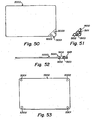
- FIGs. 50, 51 and 52 A variation on the embodiment of FIG. 46 is shown in FIGs. 50, 51 and 52 .
- the "frame” is not really a complete frame that surrounds the image area, but rather abbreviated to occupy only a corner (or, optionally, another small area out of the main image area) of the plate 5000. The parts of this embodiment are now described in detail.
- Plate 5000 has a corner region 5001 with two voids 5002 and 5003 formed therein.
- the voids 5002 and 5003 are positioned, sized and shaped to retain the corner element ( FIG. 51 , 5100) to the plate 5000.
- corner element 5100 has two retaining studs 5101 and 5102, positioned, sized and shaped to fit in the voids 5002 and 5003 of plate 5000. Also, embedded within the material of which corner element 5100 is formed is a shaped body 5103 of radiopaque material.
- the body 5103 of radiopaque material serves the function of the "back side” marker, while the shapes of the tops of studs 5101 and 5102 serve the function of the "front side” marker.
- FIG. 52 shows the corner element 5100 attached to the plate 5000, in a bottom edge view.
- a plate 5300 has a pair of "front side” markers 5301 and a pair of "back side” markers 5302. If only the “front side” markers 5301 appear, then the resulting image indicates by the corners in which the "front side” markers appear whether it has undergone post-exposure reflection. If both the "front side” markers 5301 and the “back side” markers 5302 appear, then the resulting image was exposed from the opposite side from which it was read, i.e., it underwent pre-exposure reflection. There is insufficient information in the image, alone, to determine whether that reflection has been corrected by a subsequent post-exposure reflection. However, as described elsewhere, herein, software can replace the markers in the image with markers designed to permanently indicate the correct direction. This simplified embodiment works equally well with material that must be read only from the "front side” and material that can be read from either side.
- aspects of the invention can be embodied in a plate 4700 having a phosphorescent, radiation sensitive layer 4701 and two transparent layers 4702 and 4703.
- One or the other of the two transparent layers 4702 and 4703 can be considered to be a substrate layer providing mechanical support for the structure, or a separate, transparent substrate layer (not shown) can be used.
- Transparent layers 4702 and 4703 could, in fact, be omitted, provided another substrate layer is provided, and radiopaque patterns 4704 and 4705 are provided to each side of layer 4701, for example by overprinting.
- Each transparent layer 4702 and 4703 should be functionally transparent to both the excitation wavelength and the phosphorescence wavelength of the radiation sensitive layer 4701.
- each transparent layer includes at an edge a radiopaque pattern 4704 and 4705.
- Patterns 4704 and 4705 are selected for several qualities. They may, as in this example, be the same pattern, when each is viewed from the side of the radiation sensitive layer 4701 on which the pattern is disposed.
- the patterns 4704 and 4705 should be inherently asymmetrical when the plate is exposed and viewed from the same side, as shown in FIG. 48 , so that a horizontal or vertical reflection of the pattern is readily apparent in the resulting image.
- the patterns 4704 and 4705 should combine, when exposed from one side and viewed from the other side to produce a unique pattern different from that shown in FIG. 48 , as shown in FIG. 49 .
- FIG. 49 When an image as shown in FIG. 49 is read from a plate, the operator (or the software performing the reading of the plate and storing of the image) can immediately discern that the image is reversed due to having been exposed from one side and read from the other. The image can then be reflected horizontally and the pattern shown in FIG. 49 can be replaced with the patter shown in FIG. 48 , thus permanently embedding in the image an indication of its correct orientation.
- Markers according to various aspects of embodiments of the invention described above can be made by casting low-melt temperature compositions or alloys into suitable shapes in a plate.
- Low temperature alloys including eutectic alloys of Sn, Sb, Bi, Pb and/or others are suitable.
Landscapes
- Physics & Mathematics (AREA)
- General Physics & Mathematics (AREA)
- Health & Medical Sciences (AREA)
- Life Sciences & Earth Sciences (AREA)
- Chemical & Material Sciences (AREA)
- Analytical Chemistry (AREA)
- Biochemistry (AREA)
- General Health & Medical Sciences (AREA)
- Immunology (AREA)
- Pathology (AREA)
- Apparatus For Radiation Diagnosis (AREA)
- Analysing Materials By The Use Of Radiation (AREA)
- Conversion Of X-Rays Into Visible Images (AREA)
- Radiography Using Non-Light Waves (AREA)
- Color Printing (AREA)
Applications Claiming Priority (7)
| Application Number | Priority Date | Filing Date | Title |
|---|---|---|---|
| US37232302P | 2002-04-12 | 2002-04-12 | |
| US372323P | 2002-04-12 | ||
| US43128202P | 2002-12-06 | 2002-12-06 | |
| US431282P | 2002-12-06 | ||
| US10/392,158 US20040011976A1 (en) | 2002-04-12 | 2003-03-18 | Radiation sensitive recording plate and method of making and using same |
| US392158 | 2003-03-18 | ||
| PCT/US2003/011267 WO2003087932A1 (en) | 2002-04-12 | 2003-04-14 | A radiation sensitive recording plate with orientation identifying marker, method of making, and of using same |
Publications (2)
| Publication Number | Publication Date |
|---|---|
| EP1495364A1 EP1495364A1 (en) | 2005-01-12 |
| EP1495364B1 true EP1495364B1 (en) | 2009-12-16 |
Family
ID=29255335
Family Applications (1)
| Application Number | Title | Priority Date | Filing Date |
|---|---|---|---|
| EP03719715A Expired - Lifetime EP1495364B1 (en) | 2002-04-12 | 2003-04-14 | A radiation sensitive recording plate with an orientation identifying marker and method of using same |
Country Status (7)
| Country | Link |
|---|---|
| US (1) | US20040011976A1 (https=) |
| EP (1) | EP1495364B1 (https=) |
| JP (1) | JP4870331B2 (https=) |
| AT (1) | ATE452333T1 (https=) |
| AU (1) | AU2003223578A1 (https=) |
| DE (1) | DE60330550D1 (https=) |
| WO (1) | WO2003087932A1 (https=) |
Families Citing this family (8)
| Publication number | Priority date | Publication date | Assignee | Title |
|---|---|---|---|---|
| US7563025B2 (en) * | 2002-04-12 | 2009-07-21 | Kay George W | Methods and apparatus for preserving orientation information in radiography images |
| US7311440B2 (en) * | 2004-03-31 | 2007-12-25 | Cyber Medical Imaging, Inc. | Anatomically conforming intraoral dental radiographic sensor |
| JP5526557B2 (ja) * | 2009-02-19 | 2014-06-18 | 日本電気株式会社 | 電子ペン及び電子ペンシステム |
| US20120001737A1 (en) | 2010-05-13 | 2012-01-05 | Amir Berger | Method and system for computed radiography |
| DE102014014056A1 (de) * | 2014-09-29 | 2015-06-18 | Sirona Dental Systems Gmbh | Röntgenspeicherfolie und Verfahren zur Auswertung eines Röntgenbildes |
| DE102018114460B3 (de) * | 2018-06-15 | 2019-06-06 | Dürr Dental SE | Röntgenspeicherfoliensystem |
| US11833010B2 (en) | 2020-12-23 | 2023-12-05 | Robert Kyle Koski | Device and method for dental procedure planning |
| JP7457085B2 (ja) * | 2021-11-22 | 2024-03-27 | 株式会社モリタ製作所 | 読取装置 |
Family Cites Families (12)
| Publication number | Priority date | Publication date | Assignee | Title |
|---|---|---|---|---|
| US1748490A (en) * | 1926-03-11 | 1930-02-25 | Eastman Kodak Co | X-ray dental film package |
| US2426286A (en) * | 1945-01-18 | 1947-08-26 | Frank J Stadler | Dental x-ray film identifier |
| CH564943A5 (en) * | 1974-02-25 | 1975-08-15 | Hurni Willy | X-ray plate marking pencil - contains contrast agent and shows up when exposed, also marks skin areas for indelible reproduction |
| JPH0420407Y2 (https=) * | 1988-12-19 | 1992-05-11 | ||
| US5123040A (en) * | 1990-08-27 | 1992-06-16 | Fabian Carl E | Marked x ray film with modified cassette for identifying the exposure side of a medical radiograph |
| US5202911A (en) * | 1990-08-27 | 1993-04-13 | Fabian Carl E | Markers for dental x-ray film and packets for simplified film mounting |
| US5195122A (en) * | 1991-02-13 | 1993-03-16 | Fabian Carl E | Marker for exposure side of medical radiograph included with patient identification data |
| EP0866342B1 (en) * | 1997-03-21 | 2005-03-23 | Agfa-Gevaert | Method of recording and reading a radiation image of an elongate body |
| JP2000180596A (ja) * | 1998-12-17 | 2000-06-30 | Masaharu Takeuchi | X線用グリッド |
| US6354737B1 (en) * | 1999-11-12 | 2002-03-12 | Direct Radiography Corp. | Digital image orientation marker |
| JP2001283726A (ja) * | 2000-03-31 | 2001-10-12 | Matsushita Electric Ind Co Ltd | 陰極線管の製造方法 |
| JP2001322879A (ja) * | 2000-05-10 | 2001-11-20 | Akimitsu Yabusaki | コンクリート及びコンクリートブロックの着色を兼ねた中性化防止工法 |
-
2003
- 2003-03-18 US US10/392,158 patent/US20040011976A1/en not_active Abandoned
- 2003-04-14 AU AU2003223578A patent/AU2003223578A1/en not_active Abandoned
- 2003-04-14 JP JP2003584814A patent/JP4870331B2/ja not_active Expired - Fee Related
- 2003-04-14 EP EP03719715A patent/EP1495364B1/en not_active Expired - Lifetime
- 2003-04-14 DE DE60330550T patent/DE60330550D1/de not_active Expired - Lifetime
- 2003-04-14 WO PCT/US2003/011267 patent/WO2003087932A1/en not_active Ceased
- 2003-04-14 AT AT03719715T patent/ATE452333T1/de not_active IP Right Cessation
Also Published As
| Publication number | Publication date |
|---|---|
| DE60330550D1 (de) | 2010-01-28 |
| EP1495364A1 (en) | 2005-01-12 |
| US20040011976A1 (en) | 2004-01-22 |
| AU2003223578A1 (en) | 2003-10-27 |
| JP4870331B2 (ja) | 2012-02-08 |
| JP2005522704A (ja) | 2005-07-28 |
| WO2003087932A1 (en) | 2003-10-23 |
| ATE452333T1 (de) | 2010-01-15 |
Similar Documents
| Publication | Publication Date | Title |
|---|---|---|
| US7140769B2 (en) | Radiation sensitive recording plate with orientation identifying marker, method of making, and of using same | |
| US7563025B2 (en) | Methods and apparatus for preserving orientation information in radiography images | |
| EP1495364B1 (en) | A radiation sensitive recording plate with an orientation identifying marker and method of using same | |
| US7092492B2 (en) | Universal radiologic patient positioning marker | |
| US5202911A (en) | Markers for dental x-ray film and packets for simplified film mounting | |
| US5123040A (en) | Marked x ray film with modified cassette for identifying the exposure side of a medical radiograph | |
| US5506884A (en) | Radiation phantom and test methods employing the same | |
| JP3781165B2 (ja) | 放射線画像撮像装置 | |
| EP0546040B1 (en) | Markers for dental x-ray film and packets for simplified film mounting | |
| JP2004223138A (ja) | Qcファントムおよび放射線画像読取システム | |
| US7479648B2 (en) | Methods and apparatus for imaging elongate objects | |
| US20040169149A1 (en) | Imaging plate with means for indicating improper exposure or orientation | |
| EP0475313B1 (en) | Method and apparatus for referencing a cassette and/or an intensifying screen on a radiograph | |
| US20070248256A1 (en) | System and method for producing a digital radiographic image with a notation to indicate the exposure side of the image | |
| Waynant et al. | Improved sensitivity and specificity of mammograms by producing uniform luminance from viewboxes | |
| EP4717179A1 (en) | Processing device, image combination method, program, and recording medium | |
| WO2024263582A2 (en) | Geometric calibration in an x-ray imaging system | |
| JP2006215185A (ja) | カセッテ | |
| JP3367969B2 (ja) | X線撮影装置及びx線グリッド | |
| EP1460476A1 (en) | Identification method of an image orientation | |
| US6455843B1 (en) | Alignment fixture for image quality test target | |
| JP2003195435A (ja) | 放射線撮影用カセッテ、放射線画像読み取り装置および方法 | |
| JPH07146520A (ja) | 放射線撮影用フィルムのラベルとその作成方法 | |
| KR200256220Y1 (ko) | 방사선투과검사용 필름카세트 | |
| Reddy et al. | Photoradiography |
Legal Events
| Date | Code | Title | Description |
|---|---|---|---|
| PUAI | Public reference made under article 153(3) epc to a published international application that has entered the european phase |
Free format text: ORIGINAL CODE: 0009012 |
|
| 17P | Request for examination filed |
Effective date: 20041108 |
|
| AK | Designated contracting states |
Kind code of ref document: A1 Designated state(s): AT BE BG CH CY CZ DE DK EE ES FI FR GB GR HU IE IT LI LU MC NL PT RO SE SI SK TR |
|
| AX | Request for extension of the european patent |
Extension state: AL LT LV MK |
|
| 17Q | First examination report despatched |
Effective date: 20081001 |
|
| GRAP | Despatch of communication of intention to grant a patent |
Free format text: ORIGINAL CODE: EPIDOSNIGR1 |
|
| RIC1 | Information provided on ipc code assigned before grant |
Ipc: G03C 11/02 20060101ALI20090331BHEP Ipc: G01N 23/04 20060101AFI20090331BHEP Ipc: G03B 42/04 20060101ALI20090331BHEP |
|
| RTI1 | Title (correction) |
Free format text: A RADIATION SENSITIVE RECORDING PLATE WITH AN ORIENTATION IDENTIFYING MARKER AND METHOD OF USING SAME |
|
| GRAS | Grant fee paid |
Free format text: ORIGINAL CODE: EPIDOSNIGR3 |
|
| GRAA | (expected) grant |
Free format text: ORIGINAL CODE: 0009210 |
|
| AK | Designated contracting states |
Kind code of ref document: B1 Designated state(s): AT BE BG CH CY CZ DE DK EE ES FI FR GB GR HU IE IT LI LU MC NL PT RO SE SI SK TR |
|
| REG | Reference to a national code |
Ref country code: GB Ref legal event code: FG4D |
|
| REG | Reference to a national code |
Ref country code: CH Ref legal event code: EP |
|
| REG | Reference to a national code |
Ref country code: IE Ref legal event code: FG4D |
|
| REF | Corresponds to: |
Ref document number: 60330550 Country of ref document: DE Date of ref document: 20100128 Kind code of ref document: P |
|
| REG | Reference to a national code |
Ref country code: SE Ref legal event code: TRGR |
|
| REG | Reference to a national code |
Ref country code: NL Ref legal event code: VDEP Effective date: 20091216 |
|
| PG25 | Lapsed in a contracting state [announced via postgrant information from national office to epo] |
Ref country code: FI Free format text: LAPSE BECAUSE OF FAILURE TO SUBMIT A TRANSLATION OF THE DESCRIPTION OR TO PAY THE FEE WITHIN THE PRESCRIBED TIME-LIMIT Effective date: 20091216 |
|
| PG25 | Lapsed in a contracting state [announced via postgrant information from national office to epo] |
Ref country code: SI Free format text: LAPSE BECAUSE OF FAILURE TO SUBMIT A TRANSLATION OF THE DESCRIPTION OR TO PAY THE FEE WITHIN THE PRESCRIBED TIME-LIMIT Effective date: 20091216 |
|
| PG25 | Lapsed in a contracting state [announced via postgrant information from national office to epo] |
Ref country code: AT Free format text: LAPSE BECAUSE OF FAILURE TO SUBMIT A TRANSLATION OF THE DESCRIPTION OR TO PAY THE FEE WITHIN THE PRESCRIBED TIME-LIMIT Effective date: 20091216 |
|
| PG25 | Lapsed in a contracting state [announced via postgrant information from national office to epo] |
Ref country code: ES Free format text: LAPSE BECAUSE OF FAILURE TO SUBMIT A TRANSLATION OF THE DESCRIPTION OR TO PAY THE FEE WITHIN THE PRESCRIBED TIME-LIMIT Effective date: 20100327 Ref country code: BG Free format text: LAPSE BECAUSE OF FAILURE TO SUBMIT A TRANSLATION OF THE DESCRIPTION OR TO PAY THE FEE WITHIN THE PRESCRIBED TIME-LIMIT Effective date: 20100316 Ref country code: EE Free format text: LAPSE BECAUSE OF FAILURE TO SUBMIT A TRANSLATION OF THE DESCRIPTION OR TO PAY THE FEE WITHIN THE PRESCRIBED TIME-LIMIT Effective date: 20091216 Ref country code: NL Free format text: LAPSE BECAUSE OF FAILURE TO SUBMIT A TRANSLATION OF THE DESCRIPTION OR TO PAY THE FEE WITHIN THE PRESCRIBED TIME-LIMIT Effective date: 20091216 Ref country code: RO Free format text: LAPSE BECAUSE OF FAILURE TO SUBMIT A TRANSLATION OF THE DESCRIPTION OR TO PAY THE FEE WITHIN THE PRESCRIBED TIME-LIMIT Effective date: 20091216 Ref country code: PT Free format text: LAPSE BECAUSE OF FAILURE TO SUBMIT A TRANSLATION OF THE DESCRIPTION OR TO PAY THE FEE WITHIN THE PRESCRIBED TIME-LIMIT Effective date: 20100416 |
|
| PG25 | Lapsed in a contracting state [announced via postgrant information from national office to epo] |
Ref country code: SK Free format text: LAPSE BECAUSE OF FAILURE TO SUBMIT A TRANSLATION OF THE DESCRIPTION OR TO PAY THE FEE WITHIN THE PRESCRIBED TIME-LIMIT Effective date: 20091216 Ref country code: CZ Free format text: LAPSE BECAUSE OF FAILURE TO SUBMIT A TRANSLATION OF THE DESCRIPTION OR TO PAY THE FEE WITHIN THE PRESCRIBED TIME-LIMIT Effective date: 20091216 Ref country code: BE Free format text: LAPSE BECAUSE OF FAILURE TO SUBMIT A TRANSLATION OF THE DESCRIPTION OR TO PAY THE FEE WITHIN THE PRESCRIBED TIME-LIMIT Effective date: 20091216 |
|
| PLBE | No opposition filed within time limit |
Free format text: ORIGINAL CODE: 0009261 |
|
| STAA | Information on the status of an ep patent application or granted ep patent |
Free format text: STATUS: NO OPPOSITION FILED WITHIN TIME LIMIT |
|
| PG25 | Lapsed in a contracting state [announced via postgrant information from national office to epo] |
Ref country code: GR Free format text: LAPSE BECAUSE OF FAILURE TO SUBMIT A TRANSLATION OF THE DESCRIPTION OR TO PAY THE FEE WITHIN THE PRESCRIBED TIME-LIMIT Effective date: 20100317 Ref country code: CY Free format text: LAPSE BECAUSE OF FAILURE TO SUBMIT A TRANSLATION OF THE DESCRIPTION OR TO PAY THE FEE WITHIN THE PRESCRIBED TIME-LIMIT Effective date: 20091216 |
|
| 26N | No opposition filed |
Effective date: 20100917 |
|
| PG25 | Lapsed in a contracting state [announced via postgrant information from national office to epo] |
Ref country code: MC Free format text: LAPSE BECAUSE OF NON-PAYMENT OF DUE FEES Effective date: 20100430 |
|
| REG | Reference to a national code |
Ref country code: CH Ref legal event code: PL |
|
| PG25 | Lapsed in a contracting state [announced via postgrant information from national office to epo] |
Ref country code: DK Free format text: LAPSE BECAUSE OF FAILURE TO SUBMIT A TRANSLATION OF THE DESCRIPTION OR TO PAY THE FEE WITHIN THE PRESCRIBED TIME-LIMIT Effective date: 20091216 Ref country code: IE Free format text: LAPSE BECAUSE OF NON-PAYMENT OF DUE FEES Effective date: 20100414 |
|
| PG25 | Lapsed in a contracting state [announced via postgrant information from national office to epo] |
Ref country code: LI Free format text: LAPSE BECAUSE OF NON-PAYMENT OF DUE FEES Effective date: 20100430 Ref country code: CH Free format text: LAPSE BECAUSE OF NON-PAYMENT OF DUE FEES Effective date: 20100430 |
|
| PG25 | Lapsed in a contracting state [announced via postgrant information from national office to epo] |
Ref country code: IT Free format text: LAPSE BECAUSE OF FAILURE TO SUBMIT A TRANSLATION OF THE DESCRIPTION OR TO PAY THE FEE WITHIN THE PRESCRIBED TIME-LIMIT Effective date: 20091216 |
|
| PG25 | Lapsed in a contracting state [announced via postgrant information from national office to epo] |
Ref country code: HU Free format text: LAPSE BECAUSE OF FAILURE TO SUBMIT A TRANSLATION OF THE DESCRIPTION OR TO PAY THE FEE WITHIN THE PRESCRIBED TIME-LIMIT Effective date: 20100617 Ref country code: LU Free format text: LAPSE BECAUSE OF NON-PAYMENT OF DUE FEES Effective date: 20100414 |
|
| PG25 | Lapsed in a contracting state [announced via postgrant information from national office to epo] |
Ref country code: TR Free format text: LAPSE BECAUSE OF FAILURE TO SUBMIT A TRANSLATION OF THE DESCRIPTION OR TO PAY THE FEE WITHIN THE PRESCRIBED TIME-LIMIT Effective date: 20091216 |
|
| PGFP | Annual fee paid to national office [announced via postgrant information from national office to epo] |
Ref country code: GB Payment date: 20140428 Year of fee payment: 12 |
|
| PGFP | Annual fee paid to national office [announced via postgrant information from national office to epo] |
Ref country code: SE Payment date: 20140429 Year of fee payment: 12 Ref country code: FR Payment date: 20140417 Year of fee payment: 12 Ref country code: DE Payment date: 20140429 Year of fee payment: 12 |
|
| REG | Reference to a national code |
Ref country code: DE Ref legal event code: R119 Ref document number: 60330550 Country of ref document: DE |
|
| REG | Reference to a national code |
Ref country code: SE Ref legal event code: EUG |
|
| GBPC | Gb: european patent ceased through non-payment of renewal fee |
Effective date: 20150414 |
|
| PG25 | Lapsed in a contracting state [announced via postgrant information from national office to epo] |
Ref country code: GB Free format text: LAPSE BECAUSE OF NON-PAYMENT OF DUE FEES Effective date: 20150414 Ref country code: DE Free format text: LAPSE BECAUSE OF NON-PAYMENT OF DUE FEES Effective date: 20151103 |
|
| REG | Reference to a national code |
Ref country code: FR Ref legal event code: ST Effective date: 20151231 |
|
| PG25 | Lapsed in a contracting state [announced via postgrant information from national office to epo] |
Ref country code: FR Free format text: LAPSE BECAUSE OF NON-PAYMENT OF DUE FEES Effective date: 20150430 Ref country code: SE Free format text: LAPSE BECAUSE OF NON-PAYMENT OF DUE FEES Effective date: 20150415 |