EP1494978B1 - Verfahren und vorrichtung zum biegen und vorspannen von glasscheiben - Google Patents
Verfahren und vorrichtung zum biegen und vorspannen von glasscheiben Download PDFInfo
- Publication number
- EP1494978B1 EP1494978B1 EP03720603A EP03720603A EP1494978B1 EP 1494978 B1 EP1494978 B1 EP 1494978B1 EP 03720603 A EP03720603 A EP 03720603A EP 03720603 A EP03720603 A EP 03720603A EP 1494978 B1 EP1494978 B1 EP 1494978B1
- Authority
- EP
- European Patent Office
- Prior art keywords
- glass sheet
- glass
- bending
- air
- stop means
- Prior art date
- Legal status (The legal status is an assumption and is not a legal conclusion. Google has not performed a legal analysis and makes no representation as to the accuracy of the status listed.)
- Expired - Lifetime
Links
- 239000011521 glass Substances 0.000 title claims abstract description 148
- 238000005452 bending Methods 0.000 title claims abstract description 46
- 238000000034 method Methods 0.000 title claims abstract description 22
- 238000005496 tempering Methods 0.000 title claims abstract description 9
- 238000007664 blowing Methods 0.000 claims abstract description 14
- 239000013256 coordination polymer Substances 0.000 claims abstract description 8
- 230000008093 supporting effect Effects 0.000 claims abstract description 8
- 230000000694 effects Effects 0.000 claims description 3
- 238000010438 heat treatment Methods 0.000 claims description 3
- 239000005357 flat glass Substances 0.000 description 3
- 230000003287 optical effect Effects 0.000 description 3
- 239000000919 ceramic Substances 0.000 description 1
- 239000011248 coating agent Substances 0.000 description 1
- 238000000576 coating method Methods 0.000 description 1
- 238000001816 cooling Methods 0.000 description 1
- 230000001419 dependent effect Effects 0.000 description 1
- 239000000835 fiber Substances 0.000 description 1
- 238000004519 manufacturing process Methods 0.000 description 1
- 239000000463 material Substances 0.000 description 1
Images
Classifications
-
- C—CHEMISTRY; METALLURGY
- C03—GLASS; MINERAL OR SLAG WOOL
- C03B—MANUFACTURE, SHAPING, OR SUPPLEMENTARY PROCESSES
- C03B35/00—Transporting of glass products during their manufacture, e.g. hot glass lenses, prisms
- C03B35/14—Transporting hot glass sheets or ribbons, e.g. by heat-resistant conveyor belts or bands
- C03B35/145—Transporting hot glass sheets or ribbons, e.g. by heat-resistant conveyor belts or bands by top-side transfer or supporting devices, e.g. lifting or conveying using suction
- C03B35/147—Transporting hot glass sheets or ribbons, e.g. by heat-resistant conveyor belts or bands by top-side transfer or supporting devices, e.g. lifting or conveying using suction of the non-contact type
-
- C—CHEMISTRY; METALLURGY
- C03—GLASS; MINERAL OR SLAG WOOL
- C03B—MANUFACTURE, SHAPING, OR SUPPLEMENTARY PROCESSES
- C03B23/00—Re-forming shaped glass
- C03B23/02—Re-forming glass sheets
- C03B23/023—Re-forming glass sheets by bending
- C03B23/025—Re-forming glass sheets by bending by gravity
-
- C—CHEMISTRY; METALLURGY
- C03—GLASS; MINERAL OR SLAG WOOL
- C03B—MANUFACTURE, SHAPING, OR SUPPLEMENTARY PROCESSES
- C03B23/00—Re-forming shaped glass
- C03B23/02—Re-forming glass sheets
- C03B23/023—Re-forming glass sheets by bending
- C03B23/035—Re-forming glass sheets by bending using a gas cushion or by changing gas pressure, e.g. by applying vacuum or blowing for supporting the glass while bending
-
- C—CHEMISTRY; METALLURGY
- C03—GLASS; MINERAL OR SLAG WOOL
- C03B—MANUFACTURE, SHAPING, OR SUPPLEMENTARY PROCESSES
- C03B35/00—Transporting of glass products during their manufacture, e.g. hot glass lenses, prisms
- C03B35/14—Transporting hot glass sheets or ribbons, e.g. by heat-resistant conveyor belts or bands
- C03B35/20—Transporting hot glass sheets or ribbons, e.g. by heat-resistant conveyor belts or bands by gripping tongs or supporting frames
- C03B35/202—Transporting hot glass sheets or ribbons, e.g. by heat-resistant conveyor belts or bands by gripping tongs or supporting frames by supporting frames
-
- C—CHEMISTRY; METALLURGY
- C03—GLASS; MINERAL OR SLAG WOOL
- C03B—MANUFACTURE, SHAPING, OR SUPPLEMENTARY PROCESSES
- C03B35/00—Transporting of glass products during their manufacture, e.g. hot glass lenses, prisms
- C03B35/14—Transporting hot glass sheets or ribbons, e.g. by heat-resistant conveyor belts or bands
- C03B35/22—Transporting hot glass sheets or ribbons, e.g. by heat-resistant conveyor belts or bands on a fluid support bed, e.g. on molten metal
- C03B35/24—Transporting hot glass sheets or ribbons, e.g. by heat-resistant conveyor belts or bands on a fluid support bed, e.g. on molten metal on a gas support bed
-
- C—CHEMISTRY; METALLURGY
- C03—GLASS; MINERAL OR SLAG WOOL
- C03B—MANUFACTURE, SHAPING, OR SUPPLEMENTARY PROCESSES
- C03B2225/00—Transporting hot glass sheets during their manufacture
- C03B2225/02—Means for positioning, aligning or orientating the sheets during their travel, e.g. stops
Definitions
- the invention relates to a method and an equipment for bending and tempering of a glass sheet, in which method the glass sheet is first heated up to the bending temperature in an oven while it is moved in the oven by transfer means like rotating rollers and after the bending temperature has been reached, it is transferred into a bending section, in which the glass sheet is allowed to bend on a special mould, before cooling for tempering.
- This kind of lifter is not suitable for coated, selective glass sheets, as the easily damaged coating has to be on the top side of the glass sheets due to rollers underside.
- the object of the invention is to create a new reliable method by which the glass sheet can be transferred onto a ring mould, and a glass sheet bending and tempering oven for carrying out this method. This object is achieved by the method according to claim 1 and the glass sheet bending and tempering oven according to claim 10.
- the advantage of the invention is, that it provides reliable means to transfer hot glass sheets from rollers of a roller heart oven onto a ring mould without special tools.
- the rollers and ring mould can be ordinary tools and they do not require changes.
- the glass sheets can be transferred accurately in the correct position over the ring mould.
- the top side of the glass sheet is not touched during the transfer.
- the glass sheet is not subjected to unwanted distortions, optical faults nor surface scratches.
- the glass transfer can take place in the hot oven, at the glass bending temperature and with short change over time.
- the method is well suited for medium and high capacity serial production levels.
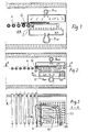
- Fig. 1 is a schematic cross section of furnace, in which there is a conveyor path made of rollers, R. At the end of conveyor path there is a ring mould, BR, immediately after the last roller. The glass G is moving over the ring mould.
- a blowing box SP furnished with nozzles, S and blower unit, Bsp.
- a glass G lifting stop means which includes air blowing box CP, the bottom side of which is a perforated plate or nozzles and blower unit Bcp. Both blowers blow hot air of the oven, as the subject section is a bending section.
- Fig. 2 shows the glass transfer phase, in which the rollers R and especially the last roller still transfers the glass over the ring mould.
- the glass support is achieved by air blowing.
- nozzles SU have been lifted above the chamber SP so that their top level is the same and just a little lower than the top level of the rollers.
- the highest point of the ring mould has to be below the roller level so that the glass will not hit the mould during the transfer.
- the unnecessary nozzles, SD are at low position and air is not blown through them.
- the blower Bsp has been adjusted so, that air flow through nozzles SU clearly can support the glass G.
- the blower Bcp causes quite small but sufficient air flow through the perforated plate towards the glass top surface so that it creates air film between the glass and perforated plate. Thus glass will never touch the perforated plate or tips of the nozzles. Rotation of rollers and especially the last roller keeps the glass moving so that it moves over the ring mould. The convey of glass during the last stage can be ensured by inclining counter surface CP down in direction of the glass travel or directing air jets in the direction of glass travel.
- the ring mould is furnished by stoppers, which stop the glass onto the correct location.
- the bottom side blowing is stopped so that the glass descends on to the ring mould BR.
- the lower side unit SP together with nozzles, can be lowered down by distance ⁇ H, so also by this movement the glass descends down onto the ring mould.
- At least the nozzles SU must be lowered down so that the glass can bend.
- the whole unit SP is lowered or both, nozzles SU and unit Sp are lowered.
- Fig. 3 describes situation of Fig. 2 seen from above, just half of the oven is pictured.
- Nozzles SU are open and blow air onto the glass.
- Nozzles SD are at lower position and are not supposed to blow air when used in connection of this ring mould.
- FIG. 4 A special detail is shown in Fig. 4, in which a powerful air jet is blown over the last roller R so that it presses the glass against the roller so that the last rollers more securely move the glass as long as the edge of the glass passes the roller.
- the distance ACF between the glass G and perforated plate of glass lifting stop means CP describes the thickness of air film between the said parts.
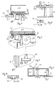
- Fig. 5 shows another arrangement for lifting and descending the nozzles, in which nozzle rows include bars L1 and L2.
- the nozzles can be turned into the position so that bars fitted onto the nozzles hit slots and the nozzles lift up together with bars or they have been turned into position, in which they do not lift up with the bars.
- a separate template located under the lower blowing box Sp can be used to lift up the nozzles.
- the lift able template lifts up via lifting bars only those nozzles, which are in the same position with the template.
- Template can be used to move the nozzles in up-or down position.
- the nozzles can also be numbered and equipped with actuators for the lifting purposes.
- Figures 6 and 7 show arrangement, in which inside the ring mould BR there is one or more support rollers CR, which support the glass and which have been equipped with rotation arrangements.
- the roller CR can be used to secure the travel of the glass up to the stoppers.
- the roller CR descends together with blower unit for the duration of bending.
- Fig. 8 shows another glass stopping arrangement, in which a pipe Sp can be pushed from top side chamber CP so, that its lower end comes down at least to the level, where the glass travels.
- This kind of stopper can be side guide or end stopper, against which glass hits.
- nozzles SN At the lower end of the stopper pipe Sp there are nozzles SN, from which air jets exit towards the glass and try to stop complete contact.
- the air can enter into the pipe Sp through holes SAF.
- Fig 8 shows a horizontally movable guide or stopper SS, which also includes air jets SN from its guiding or stopping surfaces towards the edge of the glass.
- Fig. 9 shows cross section of sliding arrangement, in which a groove, for example dovetail, fits the parts one to another thus allowing adjustment of the location of stopper or guide. The adjustment can be performed from outside of the oven by actuators, which include scale showing its position. Air jets soften the stopping of the glass or enable frictionless guiding of the glass.
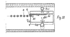
- Fig. 10 achieves supporting blowing effect onto the glass G without nozzle arrangement by use of blowing box BC under the glass.
- the air flow from blower Bsp is directed onto underside of the glass and supporting effect on the glass is created immediately after the glass leaves the rollers R and enters into the area of the mould BR.
- This arrangement is advantageous, because the nozzles are not needed at all. Only the ring mould BR has to be changed when the glass type changes.
Landscapes
- Chemical & Material Sciences (AREA)
- Engineering & Computer Science (AREA)
- Materials Engineering (AREA)
- Organic Chemistry (AREA)
- Re-Forming, After-Treatment, Cutting And Transporting Of Glass Products (AREA)
- Glass Compositions (AREA)
- Joining Of Glass To Other Materials (AREA)
Claims (10)
- Eine Methode der Biegung und des Härtens einer Glasscheibe, wo die Glasscheibe (G) zuerst in einem Ofen auf Biegetemperatur geheizt und auf Übertragungsmittel, wie rotierenden Rollen (R) bewegt wird, und wenn die Glasscheibe die Biegetemperatur erreicht hat, wird sie zu einer Biegeabteilung übertragen, wo die Glasscheibe (G) auf einem spezialen Biegering (BR) gebogen werden kann und, die genante Übertragung der Glasscheibe auf den Biegering (BR) mit auf ihr gerichteter Übertragungskraft geschieht, gekennzeichnet dadurch, dass wenn die Glasscheibe die Lage der Biegering (BR) erreicht hat, wird das Stützen der Glasscheibe (G) mit Rollen von unten zum Stützen mit Luftströmung, auf die Unterfläche der Glasscheibe gerichtet, wobei die horizontale Höhenstufe der Glasscheibe mit Sperranordnung (CP) des Steigens einer Flächenförmigen Glasscheibe oberhalb der Glasscheibe in der Lage des Biegerings (BR) instand halten wird, und Luft wird durch die Sperranordnung des Steigens geblasen, sodass sich eine Lufthaut zwischen der Glasscheibe und der Sperranordnung des Steigens der Glasscheibe bildet, weil genanntes blasen das Steigen der Glasscheibe hindert und vermeidet und Berührung der Glasscheibe mit den Sperranordnung vermeidet wird.
- Eine Methode gemäss Anspruch 1 gekennzeichnet dadurch, dass Luft auf die Unterseite der Glasscheibe aufgetragen wird, mit, verschiedenen Düsen (SU), die auf gleiche Stufe angeordnet worden sind.
- Eine Methode gemäss Anspruch 1 gekennzeichnet dadurch, dass die Düsen (SU) einzeln oder die ganze Düsenkammer in eine niedrige Lage herabgelassen werden können.
- Eine Methode gemäss Anspruch 1 gekennzeichnet dadurch, dass der Stützende Effekt die Glasscheibe (G) erreichen kann, indem man eine Kammer (BC) unter der Glasscheibe bildet, welche Kammer eine offene Fläche gegen die Glasscheiben hat, und durch Richten eines Luftstroms gegen die Glasscheibe von unten.
- Eine Methode gemäss Anspruch 1 gekennzeichnet dadurch, dass die, das Steigen der Glasscheibe stoppende Sperranordnung (CP), eine Lochplatte oder Düsenplatte ist, und Luft durch die Löcher geblasen wird, wobei der dynamische Effekt dieser Luftströmung wesentlich kleiner als der Effekt der Luftströmung, die von unten auf die untere Fläche der Glasscheibe gerichtet wird.
- Eine Methode gemäss Anspruch 1 gekennzeichnet dadurch, dass die Glasscheibe auf dem Biegering (BR) mit Hilfe der Kraft von der Rollen (R) übertragen wird,
- Eine Methode gemäss Anspruch 1 gekennzeichnet dadurch, dass die Glasscheibe auf den Biegering (BR) mit Hilfe eines, Rads (CR) unter der Glasscheibe auf den Gebiet des Biegerings übertragen wird.
- Eine Methode gemäss Anspruch 1 gekennzeichnet dadurch, dass zur Übertragung der Glasscheibe mit Rollen (R), Wasserstrahlen auf die Oberfläche der Glasscheibe gerichtet werden, um an die Rollen die Glasscheibe nach unten zu drücken, und zwar um den Übertragungseffekt zu verbessern.
- Eine Methode gemäss Anspruch 1 gekennzeichnet dadurch, dass das Gelangen und Sperren der Glasscheibe an die Rollen mit mechanischen Sperren (Sp), (Ss)gesteuert werden, mit Hilfe welchen aus den Kontaktflächen Luft gegen die Glaskante geblasen wird.
- Ein Ofen für Biegen und Härten einer Glasscheibe (G), der Ofen bestehend aus einer Abteilung für Glasheizung, wo die Glasscheibe auf Biegetemperatur geheizt wird und aus, einer Biegeabteilung und Übertragungsmittel, wie Rollen (R) auf welchem die Glasscheibe bei Biegetemperatur in die Biegeabteilung übertragen wird, wo es einen Biegering (BR) gibt, auf dem die Glasscheibe bevor Härten biegen darf, gekennzeichnet dadurch, dass es, zur Übertragung der Glasscheibe auf den Biegering (BR), in die Ausrüstung an den Biegering unter dem Glas (BR) eine Luftblaseanordung gehört, mit dem die Glas ragenden Rollen ersetzt weden und, um die Höhenstufe während der Übertragung beizubehalten, enthält die Ausrüstung eine Sperranordnung (CP) auf der Glasscheibe an den Biegering (BR) und die Sperranordnung enthält auch eine Luftblaseanordung (Bcp) mit einem Lochplatte oder ein Satz Düsen in Flächenform, damit sich eine Lufthaut zwischen Glasscheibe (G) und Sperranordnung bildet.
Applications Claiming Priority (3)
| Application Number | Priority Date | Filing Date | Title |
|---|---|---|---|
| FI20020632 | 2002-04-03 | ||
| FI20020632A FI115045B (fi) | 2002-04-03 | 2002-04-03 | Menetelmä ja laitteisto lasin taivutuskarkaisemiseksi |
| PCT/FI2003/000252 WO2003082754A1 (en) | 2002-04-03 | 2003-04-02 | Method and equipment for bending and tempering of glass |
Publications (2)
| Publication Number | Publication Date |
|---|---|
| EP1494978A1 EP1494978A1 (de) | 2005-01-12 |
| EP1494978B1 true EP1494978B1 (de) | 2006-09-13 |
Family
ID=8563685
Family Applications (1)
| Application Number | Title | Priority Date | Filing Date |
|---|---|---|---|
| EP03720603A Expired - Lifetime EP1494978B1 (de) | 2002-04-03 | 2003-04-02 | Verfahren und vorrichtung zum biegen und vorspannen von glasscheiben |
Country Status (8)
| Country | Link |
|---|---|
| US (1) | US20050223745A1 (de) |
| EP (1) | EP1494978B1 (de) |
| CN (1) | CN100591634C (de) |
| AT (1) | ATE339394T1 (de) |
| AU (1) | AU2003224186A1 (de) |
| DE (1) | DE60308347T2 (de) |
| FI (1) | FI115045B (de) |
| WO (1) | WO2003082754A1 (de) |
Families Citing this family (3)
| Publication number | Priority date | Publication date | Assignee | Title |
|---|---|---|---|---|
| PL3538498T3 (pl) * | 2016-11-11 | 2023-06-26 | Pilkington Group Limited | Sposób kształtowania tafli szkła i wykorzystywana w ten sposób linia kształtowania szkła |
| CN107188400A (zh) * | 2017-05-22 | 2017-09-22 | 成都扬中新能源科技有限公司 | 应用于电热膜元件的预热方法 |
| CN117228933B (zh) * | 2023-08-25 | 2025-03-25 | 咸宁南玻光电玻璃有限公司 | 辊下密封系统及浮法玻璃生产的调节方法 |
Family Cites Families (12)
| Publication number | Priority date | Publication date | Assignee | Title |
|---|---|---|---|---|
| US3338695A (en) * | 1962-09-14 | 1967-08-29 | Libbey Owens Ford Glass Co | Method and apparatus for press bending and tempering glass sheets |
| US3665730A (en) * | 1970-06-11 | 1972-05-30 | Frederick D Linzer | Apparatus for simultaneously supporting, cooling and shaping glass sheet and the like |
| US4282026A (en) * | 1978-01-25 | 1981-08-04 | Mcmaster Harold | Apparatus for bending and tempering glass |
| US4204854A (en) * | 1978-05-01 | 1980-05-27 | Mcmaster Harold | Apparatus and method for bending glass sheets |
| CA1120726A (en) * | 1978-05-01 | 1982-03-30 | Harold A. Mcmaster | Apparatus and method for bending glass |
| FR2597855A1 (fr) * | 1986-04-29 | 1987-10-30 | Saint Gobain Vitrage | Transfert de plaques de verre en vue de leur bombage |
| US5246477A (en) * | 1990-02-08 | 1993-09-21 | Wsp Ingenieurgesellschaft Fur Waermetechnik, Stroemungstechnik Und Prozesstechnik Mit Beschraenkter Haftung | Apparatus for the arching of glass sheets heated to the softening temperature |
| FR2691454B1 (fr) * | 1992-05-21 | 1994-07-08 | Saint Gobain Vitrage Int | Procede et dispositif d'obtention de feuilles de verre bombees. |
| US5320329A (en) * | 1993-02-16 | 1994-06-14 | Surface Combustion, Inc. | Pressure pad for stably floating thin strip |
| JP3587212B2 (ja) * | 1993-10-28 | 2004-11-10 | 旭硝子株式会社 | 加熱炉の熱量調整装置 |
| FI96845C (fi) * | 1994-10-25 | 1996-09-10 | Risto Nikander | Menetelmä ja laitteisto lasilevyn taivutuskarkaisussa |
| US6505483B1 (en) * | 2000-02-25 | 2003-01-14 | Surface Combustion, Inc. | Glass transportation system |
-
2002
- 2002-04-03 FI FI20020632A patent/FI115045B/fi not_active IP Right Cessation
-
2003
- 2003-04-02 EP EP03720603A patent/EP1494978B1/de not_active Expired - Lifetime
- 2003-04-02 AU AU2003224186A patent/AU2003224186A1/en not_active Abandoned
- 2003-04-02 CN CN03809546A patent/CN100591634C/zh not_active Expired - Fee Related
- 2003-04-02 DE DE60308347T patent/DE60308347T2/de not_active Expired - Fee Related
- 2003-04-02 US US10/509,939 patent/US20050223745A1/en not_active Abandoned
- 2003-04-02 AT AT03720603T patent/ATE339394T1/de not_active IP Right Cessation
- 2003-04-02 WO PCT/FI2003/000252 patent/WO2003082754A1/en not_active Ceased
Also Published As
| Publication number | Publication date |
|---|---|
| FI20020632A7 (fi) | 2003-10-04 |
| WO2003082754A1 (en) | 2003-10-09 |
| AU2003224186A1 (en) | 2003-10-13 |
| CN1649798A (zh) | 2005-08-03 |
| ATE339394T1 (de) | 2006-10-15 |
| EP1494978A1 (de) | 2005-01-12 |
| US20050223745A1 (en) | 2005-10-13 |
| CN100591634C (zh) | 2010-02-24 |
| FI20020632A0 (fi) | 2002-04-03 |
| FI115045B (fi) | 2005-02-28 |
| DE60308347T2 (de) | 2007-04-26 |
| DE60308347D1 (de) | 2006-10-26 |
Similar Documents
| Publication | Publication Date | Title |
|---|---|---|
| US4662925A (en) | Horizontal press bending of heat softened glass sheets | |
| EP0228597B1 (de) | Pendelstützrahmen für Vacuum-Entnahmeeinrichtung | |
| EP1484290B1 (de) | Verfahren zum biegeformen von glasplatten und vorrichtung | |
| FI79517B (fi) | Behandlingssystem foer glasskiva, vilket innefattar en oevre oeverfoeringsanordning. | |
| US4666492A (en) | Method and apparatus for shaping glass sheets | |
| CN107531545B (zh) | 玻璃片的弯曲 | |
| US4767437A (en) | Horizontal press bending using a splitting vacuum/pressure pickup | |
| CA1241197A (en) | Shaping glass sheets to complicated shapes | |
| EP0229337B1 (de) | Scheibenpositionierungssystem | |
| EP0788466B1 (de) | Verfahren und vorrichtung zum biegen und härten einer glasscheibe | |
| CA1152327A (en) | Method and apparatus for shaping glass sheets using deformable vacuum mold | |
| MXPA06002140A (es) | Molde de superficie flexible y metodo de uso. | |
| US4432782A (en) | Support for hot glass sheets of non-rectangular outline prior to bending | |
| US4767434A (en) | Horizontal press bending pickup and delivery system | |
| KR100268140B1 (ko) | 성형 스테이션에서 글래스 시트를 지지 및 운송하기 위한 장치 및 방법 | |
| FI88909B (fi) | Foerfarande och anordning foer boejning och/eller haerdning av glas | |
| US20050223745A1 (en) | Method and equipment for bending and tempering of glass | |
| US4840657A (en) | Process and apparatus for bending glass plates | |
| JPS61295244A (ja) | ガラス板成形装置 | |
| JP2003335533A (ja) | ガラス板の曲げ成形方法および装置 | |
| EP1240112B1 (de) | Verfahren und vorrichtung zum biegen von glass | |
| KR950031949A (ko) | 유리판 벤딩 방법 및 장치 | |
| JPH05170468A (ja) | 板状材の曲げ成形装置 |
Legal Events
| Date | Code | Title | Description |
|---|---|---|---|
| PUAI | Public reference made under article 153(3) epc to a published international application that has entered the european phase |
Free format text: ORIGINAL CODE: 0009012 |
|
| 17P | Request for examination filed |
Effective date: 20041102 |
|
| AK | Designated contracting states |
Kind code of ref document: A1 Designated state(s): AT BE BG CH CY CZ DE DK EE ES FI FR GB GR HU IE IT LI LU MC NL PT RO SE SI SK TR |
|
| AX | Request for extension of the european patent |
Extension state: AL LT LV MK |
|
| GRAP | Despatch of communication of intention to grant a patent |
Free format text: ORIGINAL CODE: EPIDOSNIGR1 |
|
| RTI1 | Title (correction) |
Free format text: METHOD AND EQUIPMENT FOR BENDING AND TEMPERING OF GLASS SHEETS |
|
| GRAS | Grant fee paid |
Free format text: ORIGINAL CODE: EPIDOSNIGR3 |
|
| GRAA | (expected) grant |
Free format text: ORIGINAL CODE: 0009210 |
|
| AK | Designated contracting states |
Kind code of ref document: B1 Designated state(s): AT BE BG CH CY CZ DE DK EE ES FI FR GB GR HU IE IT LI LU MC NL PT RO SE SI SK TR |
|
| PG25 | Lapsed in a contracting state [announced via postgrant information from national office to epo] |
Ref country code: IT Free format text: LAPSE BECAUSE OF FAILURE TO SUBMIT A TRANSLATION OF THE DESCRIPTION OR TO PAY THE FEE WITHIN THE PRESCRIBED TIME-LIMIT;WARNING: LAPSES OF ITALIAN PATENTS WITH EFFECTIVE DATE BEFORE 2007 MAY HAVE OCCURRED AT ANY TIME BEFORE 2007. THE CORRECT EFFECTIVE DATE MAY BE DIFFERENT FROM THE ONE RECORDED. Effective date: 20060913 Ref country code: NL Free format text: LAPSE BECAUSE OF FAILURE TO SUBMIT A TRANSLATION OF THE DESCRIPTION OR TO PAY THE FEE WITHIN THE PRESCRIBED TIME-LIMIT Effective date: 20060913 Ref country code: BE Free format text: LAPSE BECAUSE OF FAILURE TO SUBMIT A TRANSLATION OF THE DESCRIPTION OR TO PAY THE FEE WITHIN THE PRESCRIBED TIME-LIMIT Effective date: 20060913 Ref country code: RO Free format text: LAPSE BECAUSE OF FAILURE TO SUBMIT A TRANSLATION OF THE DESCRIPTION OR TO PAY THE FEE WITHIN THE PRESCRIBED TIME-LIMIT Effective date: 20060913 Ref country code: SI Free format text: LAPSE BECAUSE OF FAILURE TO SUBMIT A TRANSLATION OF THE DESCRIPTION OR TO PAY THE FEE WITHIN THE PRESCRIBED TIME-LIMIT Effective date: 20060913 Ref country code: FI Free format text: LAPSE BECAUSE OF FAILURE TO SUBMIT A TRANSLATION OF THE DESCRIPTION OR TO PAY THE FEE WITHIN THE PRESCRIBED TIME-LIMIT Effective date: 20060913 Ref country code: AT Free format text: LAPSE BECAUSE OF FAILURE TO SUBMIT A TRANSLATION OF THE DESCRIPTION OR TO PAY THE FEE WITHIN THE PRESCRIBED TIME-LIMIT Effective date: 20060913 Ref country code: SK Free format text: LAPSE BECAUSE OF FAILURE TO SUBMIT A TRANSLATION OF THE DESCRIPTION OR TO PAY THE FEE WITHIN THE PRESCRIBED TIME-LIMIT Effective date: 20060913 Ref country code: CH Free format text: LAPSE BECAUSE OF FAILURE TO SUBMIT A TRANSLATION OF THE DESCRIPTION OR TO PAY THE FEE WITHIN THE PRESCRIBED TIME-LIMIT Effective date: 20060913 Ref country code: CZ Free format text: LAPSE BECAUSE OF FAILURE TO SUBMIT A TRANSLATION OF THE DESCRIPTION OR TO PAY THE FEE WITHIN THE PRESCRIBED TIME-LIMIT Effective date: 20060913 Ref country code: LI Free format text: LAPSE BECAUSE OF FAILURE TO SUBMIT A TRANSLATION OF THE DESCRIPTION OR TO PAY THE FEE WITHIN THE PRESCRIBED TIME-LIMIT Effective date: 20060913 |
|
| REG | Reference to a national code |
Ref country code: GB Ref legal event code: FG4D |
|
| REG | Reference to a national code |
Ref country code: CH Ref legal event code: EP |
|
| REG | Reference to a national code |
Ref country code: IE Ref legal event code: FG4D |
|
| REF | Corresponds to: |
Ref document number: 60308347 Country of ref document: DE Date of ref document: 20061026 Kind code of ref document: P |
|
| PG25 | Lapsed in a contracting state [announced via postgrant information from national office to epo] |
Ref country code: BG Free format text: LAPSE BECAUSE OF FAILURE TO SUBMIT A TRANSLATION OF THE DESCRIPTION OR TO PAY THE FEE WITHIN THE PRESCRIBED TIME-LIMIT Effective date: 20061213 Ref country code: DK Free format text: LAPSE BECAUSE OF FAILURE TO SUBMIT A TRANSLATION OF THE DESCRIPTION OR TO PAY THE FEE WITHIN THE PRESCRIBED TIME-LIMIT Effective date: 20061213 Ref country code: SE Free format text: LAPSE BECAUSE OF FAILURE TO SUBMIT A TRANSLATION OF THE DESCRIPTION OR TO PAY THE FEE WITHIN THE PRESCRIBED TIME-LIMIT Effective date: 20061213 |
|
| PG25 | Lapsed in a contracting state [announced via postgrant information from national office to epo] |
Ref country code: ES Free format text: LAPSE BECAUSE OF FAILURE TO SUBMIT A TRANSLATION OF THE DESCRIPTION OR TO PAY THE FEE WITHIN THE PRESCRIBED TIME-LIMIT Effective date: 20061224 |
|
| PG25 | Lapsed in a contracting state [announced via postgrant information from national office to epo] |
Ref country code: PT Free format text: LAPSE BECAUSE OF FAILURE TO SUBMIT A TRANSLATION OF THE DESCRIPTION OR TO PAY THE FEE WITHIN THE PRESCRIBED TIME-LIMIT Effective date: 20070226 |
|
| NLV1 | Nl: lapsed or annulled due to failure to fulfill the requirements of art. 29p and 29m of the patents act | ||
| REG | Reference to a national code |
Ref country code: CH Ref legal event code: PL |
|
| ET | Fr: translation filed | ||
| PLBE | No opposition filed within time limit |
Free format text: ORIGINAL CODE: 0009261 |
|
| STAA | Information on the status of an ep patent application or granted ep patent |
Free format text: STATUS: NO OPPOSITION FILED WITHIN TIME LIMIT |
|
| 26N | No opposition filed |
Effective date: 20070614 |
|
| PGFP | Annual fee paid to national office [announced via postgrant information from national office to epo] |
Ref country code: IT Payment date: 20070629 Year of fee payment: 5 |
|
| PG25 | Lapsed in a contracting state [announced via postgrant information from national office to epo] |
Ref country code: GR Free format text: LAPSE BECAUSE OF FAILURE TO SUBMIT A TRANSLATION OF THE DESCRIPTION OR TO PAY THE FEE WITHIN THE PRESCRIBED TIME-LIMIT Effective date: 20061214 |
|
| PG25 | Lapsed in a contracting state [announced via postgrant information from national office to epo] |
Ref country code: IE Free format text: LAPSE BECAUSE OF NON-PAYMENT OF DUE FEES Effective date: 20070402 |
|
| PG25 | Lapsed in a contracting state [announced via postgrant information from national office to epo] |
Ref country code: EE Free format text: LAPSE BECAUSE OF FAILURE TO SUBMIT A TRANSLATION OF THE DESCRIPTION OR TO PAY THE FEE WITHIN THE PRESCRIBED TIME-LIMIT Effective date: 20060913 |
|
| PG25 | Lapsed in a contracting state [announced via postgrant information from national office to epo] |
Ref country code: MC Free format text: LAPSE BECAUSE OF NON-PAYMENT OF DUE FEES Effective date: 20070430 |
|
| PGFP | Annual fee paid to national office [announced via postgrant information from national office to epo] |
Ref country code: GB Payment date: 20090302 Year of fee payment: 7 |
|
| PG25 | Lapsed in a contracting state [announced via postgrant information from national office to epo] |
Ref country code: LU Free format text: LAPSE BECAUSE OF NON-PAYMENT OF DUE FEES Effective date: 20070402 Ref country code: IT Free format text: LAPSE BECAUSE OF NON-PAYMENT OF DUE FEES Effective date: 20080402 Ref country code: CY Free format text: LAPSE BECAUSE OF FAILURE TO SUBMIT A TRANSLATION OF THE DESCRIPTION OR TO PAY THE FEE WITHIN THE PRESCRIBED TIME-LIMIT Effective date: 20060913 |
|
| PGFP | Annual fee paid to national office [announced via postgrant information from national office to epo] |
Ref country code: DE Payment date: 20090615 Year of fee payment: 7 |
|
| PG25 | Lapsed in a contracting state [announced via postgrant information from national office to epo] |
Ref country code: TR Free format text: LAPSE BECAUSE OF FAILURE TO SUBMIT A TRANSLATION OF THE DESCRIPTION OR TO PAY THE FEE WITHIN THE PRESCRIBED TIME-LIMIT Effective date: 20060913 Ref country code: HU Free format text: LAPSE BECAUSE OF FAILURE TO SUBMIT A TRANSLATION OF THE DESCRIPTION OR TO PAY THE FEE WITHIN THE PRESCRIBED TIME-LIMIT Effective date: 20070314 |
|
| GBPC | Gb: european patent ceased through non-payment of renewal fee |
Effective date: 20100402 |
|
| PGFP | Annual fee paid to national office [announced via postgrant information from national office to epo] |
Ref country code: FR Payment date: 20101110 Year of fee payment: 8 |
|
| PG25 | Lapsed in a contracting state [announced via postgrant information from national office to epo] |
Ref country code: DE Free format text: LAPSE BECAUSE OF NON-PAYMENT OF DUE FEES Effective date: 20101103 |
|
| PG25 | Lapsed in a contracting state [announced via postgrant information from national office to epo] |
Ref country code: GB Free format text: LAPSE BECAUSE OF NON-PAYMENT OF DUE FEES Effective date: 20100402 |
|
| REG | Reference to a national code |
Ref country code: FR Ref legal event code: ST Effective date: 20111230 |
|
| PG25 | Lapsed in a contracting state [announced via postgrant information from national office to epo] |
Ref country code: FR Free format text: LAPSE BECAUSE OF NON-PAYMENT OF DUE FEES Effective date: 20110502 |