EP1494934B1 - Synthetic bottle closure - Google Patents
Synthetic bottle closure Download PDFInfo
- Publication number
- EP1494934B1 EP1494934B1 EP03701357A EP03701357A EP1494934B1 EP 1494934 B1 EP1494934 B1 EP 1494934B1 EP 03701357 A EP03701357 A EP 03701357A EP 03701357 A EP03701357 A EP 03701357A EP 1494934 B1 EP1494934 B1 EP 1494934B1
- Authority
- EP
- European Patent Office
- Prior art keywords
- bottle
- closure
- mouth
- further characterized
- seal
- Prior art date
- Legal status (The legal status is an assumption and is not a legal conclusion. Google has not performed a legal analysis and makes no representation as to the accuracy of the status listed.)
- Expired - Lifetime
Links
- 239000000463 material Substances 0.000 claims description 24
- 230000000694 effects Effects 0.000 claims description 17
- 239000004033 plastic Substances 0.000 claims description 17
- 229920003023 plastic Polymers 0.000 claims description 17
- 238000007789 sealing Methods 0.000 claims description 15
- 239000007789 gas Substances 0.000 claims description 13
- 230000006835 compression Effects 0.000 claims description 11
- 238000007906 compression Methods 0.000 claims description 11
- 238000000605 extraction Methods 0.000 claims description 9
- 239000002184 metal Substances 0.000 claims description 9
- 229910052751 metal Inorganic materials 0.000 claims description 9
- 239000002775 capsule Substances 0.000 claims description 6
- 238000000034 method Methods 0.000 claims description 5
- 239000007788 liquid Substances 0.000 claims description 4
- QVGXLLKOCUKJST-UHFFFAOYSA-N atomic oxygen Chemical compound [O] QVGXLLKOCUKJST-UHFFFAOYSA-N 0.000 claims description 3
- 239000001301 oxygen Substances 0.000 claims description 3
- 229910052760 oxygen Inorganic materials 0.000 claims description 3
- 238000002347 injection Methods 0.000 claims 1
- 239000007924 injection Substances 0.000 claims 1
- 239000002991 molded plastic Substances 0.000 claims 1
- 239000003566 sealing material Substances 0.000 claims 1
- 239000007799 cork Substances 0.000 description 11
- 230000008901 benefit Effects 0.000 description 5
- 239000011248 coating agent Substances 0.000 description 4
- 238000000576 coating method Methods 0.000 description 4
- 239000011521 glass Substances 0.000 description 3
- 239000012858 resilient material Substances 0.000 description 3
- 239000004411 aluminium Substances 0.000 description 2
- 229910052782 aluminium Inorganic materials 0.000 description 2
- XAGFODPZIPBFFR-UHFFFAOYSA-N aluminium Chemical compound [Al] XAGFODPZIPBFFR-UHFFFAOYSA-N 0.000 description 2
- 208000015181 infectious disease Diseases 0.000 description 2
- 238000001746 injection moulding Methods 0.000 description 2
- 238000003780 insertion Methods 0.000 description 2
- 230000037431 insertion Effects 0.000 description 2
- 238000004519 manufacturing process Methods 0.000 description 2
- 238000011160 research Methods 0.000 description 2
- 238000003860 storage Methods 0.000 description 2
- 229920001328 Polyvinylidene chloride Polymers 0.000 description 1
- 235000009754 Vitis X bourquina Nutrition 0.000 description 1
- 235000012333 Vitis X labruscana Nutrition 0.000 description 1
- 235000014787 Vitis vinifera Nutrition 0.000 description 1
- 240000006365 Vitis vinifera Species 0.000 description 1
- 239000005030 aluminium foil Substances 0.000 description 1
- 238000013459 approach Methods 0.000 description 1
- 230000004888 barrier function Effects 0.000 description 1
- 230000005540 biological transmission Effects 0.000 description 1
- 238000005336 cracking Methods 0.000 description 1
- 238000011161 development Methods 0.000 description 1
- 239000000428 dust Substances 0.000 description 1
- 238000002474 experimental method Methods 0.000 description 1
- 239000000796 flavoring agent Substances 0.000 description 1
- 235000019634 flavors Nutrition 0.000 description 1
- 239000006261 foam material Substances 0.000 description 1
- 239000011888 foil Substances 0.000 description 1
- 235000013305 food Nutrition 0.000 description 1
- 238000002372 labelling Methods 0.000 description 1
- 230000007774 longterm Effects 0.000 description 1
- 229930014626 natural product Natural products 0.000 description 1
- 230000003647 oxidation Effects 0.000 description 1
- 238000007254 oxidation reaction Methods 0.000 description 1
- 230000035699 permeability Effects 0.000 description 1
- 230000000704 physical effect Effects 0.000 description 1
- 239000005033 polyvinylidene chloride Substances 0.000 description 1
- 230000009467 reduction Effects 0.000 description 1
- 229920002994 synthetic fiber Polymers 0.000 description 1
- CLYZNABPUKUSDX-UHFFFAOYSA-N trichloromethoxybenzene Chemical class ClC(Cl)(Cl)OC1=CC=CC=C1 CLYZNABPUKUSDX-UHFFFAOYSA-N 0.000 description 1
Images


Classifications
-
- B—PERFORMING OPERATIONS; TRANSPORTING
- B65—CONVEYING; PACKING; STORING; HANDLING THIN OR FILAMENTARY MATERIAL
- B65D—CONTAINERS FOR STORAGE OR TRANSPORT OF ARTICLES OR MATERIALS, e.g. BAGS, BARRELS, BOTTLES, BOXES, CANS, CARTONS, CRATES, DRUMS, JARS, TANKS, HOPPERS, FORWARDING CONTAINERS; ACCESSORIES, CLOSURES, OR FITTINGS THEREFOR; PACKAGING ELEMENTS; PACKAGES
- B65D39/00—Closures arranged within necks or pouring openings or in discharge apertures, e.g. stoppers
- B65D39/0005—Closures arranged within necks or pouring openings or in discharge apertures, e.g. stoppers made in one piece
- B65D39/0023—Plastic cap-shaped hollow plugs
-
- B—PERFORMING OPERATIONS; TRANSPORTING
- B65—CONVEYING; PACKING; STORING; HANDLING THIN OR FILAMENTARY MATERIAL
- B65D—CONTAINERS FOR STORAGE OR TRANSPORT OF ARTICLES OR MATERIALS, e.g. BAGS, BARRELS, BOTTLES, BOXES, CANS, CARTONS, CRATES, DRUMS, JARS, TANKS, HOPPERS, FORWARDING CONTAINERS; ACCESSORIES, CLOSURES, OR FITTINGS THEREFOR; PACKAGING ELEMENTS; PACKAGES
- B65D39/00—Closures arranged within necks or pouring openings or in discharge apertures, e.g. stoppers
- B65D39/0052—Closures arranged within necks or pouring openings or in discharge apertures, e.g. stoppers made in more than one piece
- B65D39/007—Plastic cap-shaped hollow plugs
-
- B—PERFORMING OPERATIONS; TRANSPORTING
- B65—CONVEYING; PACKING; STORING; HANDLING THIN OR FILAMENTARY MATERIAL
- B65D—CONTAINERS FOR STORAGE OR TRANSPORT OF ARTICLES OR MATERIALS, e.g. BAGS, BARRELS, BOTTLES, BOXES, CANS, CARTONS, CRATES, DRUMS, JARS, TANKS, HOPPERS, FORWARDING CONTAINERS; ACCESSORIES, CLOSURES, OR FITTINGS THEREFOR; PACKAGING ELEMENTS; PACKAGES
- B65D51/00—Closures not otherwise provided for
- B65D51/18—Arrangements of closures with protective outer cap-like covers or of two or more co-operating closures
Definitions
- This invention relates to a closure particularly of a type appropriate for closing bottles.
- natural cork Despite being produced from an inherently variable natural product, natural cork has the advantageous characteristic of having an appropriate resiliency so that it can be used to tightly close a bottle top by being inserted inside the mouth in such a way that it will then effect substantial expansion against the inner surface of the bottle mouth to form a liquid and gas seal.
- This approach includes a metal cap which is rolled into a screw thread outside a bottle neck and is able to hold under compression therefore a gasket or seal between an underneath surface of the top of the cap and the top rim of the mouth of the bottle.
- a bottle closure according to the preamble of appended claim 1 is known through US-A- 4 342 400 .
- An object of this invention is to provide a bottle closure of the type defined in US-A-4 342 400 having an improved resistance of oxygen passage.
- the body is made from plastics material.
- the inwardly directed lip is attached to a remainder of the body by means which are adapted so that the lip can be manually torn from the remainder of the body whereby to remove the Interlocking effect.
- the inwardly directed lip is provided by a tear away strip.
- the inner portion of the body provides an outer surface which is provided by a thin wall such that there can be effected substantial resilience to maintain a sealing engagement with the inner surface of the mouth of the bottle thereby.
- the advantage is to provide the familiar "popping" sound and this Is achieved by ensuring that at least during some of the extraction of the closure, there will be caused a sufficient sealing so as to cause a temporary reduction In the pressure of gas above liquid within the bottle and therefore effect a sudden release of this when the inner portion of the closure breaks clear from a sealing engagement within the mouth of the bottle.
- the bottle is of glass.
- the bottle closure is first characterised
- the body Is comprised of at least two parts which are assembled together with a seal held between the two parts where one of the parts is comprising the portion of the body adaptably located within the mouth of the body.
- the two parts are joined by a metal means projecting mutually through the respective parts.
- the two parts are joined by at least one plastic finger extending through the seal.
- this can be said to reside in the method of closure of a bottle which includes the steps of inserting a closure according to any one of the above features into a bottle including forcing the inwardly directed lip to ride over and behind the edge of the integral collar so that this will, in this position, effect substantive compression of a seal between the body of the closure and an uppermost edge of the rim of the bottle.
- the body includes means adapted to receive a further member.
- such a further member can include a projecting portion extending into the inner portion of the body so as to be supported thereby and including a further part or parts providing visually attractive features.
- FIGS. 1 and 2 the bottle closure of another type than the present invention as illustrated In FIGS. 1 and 2 .
- closure 1 which is, in this case, shown as closing a mouth 2 of a bottle 3.
- the bottle is made of glass and has an external outwardly extending integral collar 4 which extends fully around an outside of the neck of the bottle and is of a constant shape and size at any location around the periphery.
- seal 5 held under compression against an uppermost rim 6 of the bottle mouth 2 and surface 7, which is adapted to engage with compression force the seal 5.
- This portion includes a bulbous section 9 which is provided by a thin wall section of plastics material given that the closure generally is made from plastics material, such that when the thin wall of the bulbous section 9 is compressed as when it passes through the narrower section 10 of the bottle 3, then it will Internally compress and effect sufficient compression to effect a sealing with the Inner sides of the bottle neck during an extraction process.
- a "popping" sound is achieved by having the position of the seal somewhat below the mouth prior to extraction so that there will be upon extraction an evacuation of the headspace within the bottle.
- the depth of the bulbous portion in this embodiment is approximately 25 millimeters.
- This sealing effect will also conventionally apply when the portion 8 is inserted within the mouth 2 but it will depend upon the tolerance of the inner surface 11 of the bottle mouth so that if this is a little larger, then as shown in the drawings, there might not be contact during storage although when it is extracted, there will be this sealing to effect a "popping" sound.
- the shape of the thin wall bulbous section 9 is shown, so as to be supported by a cylindrical part 12 and an arcuate portion, which together then defines a concave area 14.
- An outer surround 15 engages with interlocking fit by having an inwardly extending lip 16, the outwardly extending lowermost step 17 of the collar 4.
- a detachable strip shown at 18, which is secured to a remainder of the body of the closure 1 by a weakened portion at 19 which substantially surrounds, but not totally, the surround 15.
- An extended tab 20 provides for a first location and pull tab position which then assists in a consumer sufficiently removing this tear off tab portion so that there will be either negligible or no resistance to then subsequent removal by reason of any interlocking fit.
- Such a tearable strip shall be attached to the main body of the closure with sufficient strength so that it will be able to retain the seal 5 under compression over a substantial period of time.
- the body is intended to be manufactured by injection moulding from plastics material where the plastics material, being in contact with product within a bottle will be of a food grade character.
- a characteristic of this closure is that then there is provided a snap-on closure, which then provides a very substantive sealing effect while also providing a "popping" sound when being removed.
- the functional features of the bottle shown at 30 including a mouth 31 and an Inner engaged surface 32, a compression seal 33 and a plastics body 34 are the same as in the first embodiment.
- step 35 which firstly is adapted to act with Inwardly extending protrudence 36 and inwardly extending step 37.
- the cap 40 can be made in any decorative form and support any labeling and is such that when the closure 34 is to be accessed for removal, a first step is to lift the cap 40 to a position as is shown In FIG. 4 from FIG. 3 .
- cap in this case, is shown with a level top, this can include extended tops or any decorative finish appropriate to the application but also to enable quick recognition of a particular brand where the extension may be in the form of a particularly well-recognized logo.
- This cap conventionally would also be manufactured from plastics material by Injection moulding.
- the difference here is that there is an Inwardly projecting part 50 which is integrally moulded as part of the total body 51 where there is also an outer surround 52 which is intended to be located on top of the bottle 53 by engagement of an Inwardly directly step 54 to hold the body 51 in such a closing position.
- a substantially non permeable sheet 61 which is held by friction between the downwardly projecting wall 50 where there is also a lowermost coating surface 62 and an uppermost foam material providing additional resiliency at 63.
- the body 70 is assembled from previously separable parts and there is an inwardly projecting part 71, a top 72 and an outwardly extending surrounding part 73.
- This outwardly surrounding part 73 also includes a tear away portion 74 which Includes sufficient part of the inwardly directed step at 75 so that when the tear away part is torn away, this will allow at least reasonable removal of the body 70 from the closing position as shown.
- the bottle 76 has its upper most mouth defined by the tops at 77 but in this case, there is a substantially resilient wad 78 which extends fully from side 79 to side 80 and has In front of it the sheet 81 which is made from an Impermeable metal In this case aluminium, and there Is an underneath plastics coating, In this case PVDC, on this at 82.
- an Impermeable metal In this case aluminium, and there Is an underneath plastics coating, In this case PVDC, on this at 82.
- a staple 83 which is passed through a transverse top part 84 of the downwardly projecting part 71 and the staple has its ends outwardly turned at 85.
- the downwardly projecting part 71 includes a lowermost bulbous part 86, which allows for a resilient bearing surface.
- This embodiment therefore again as with others combines both the possibility of location of the cap simply with a snap on fit and by having the necessity of a tear away strip to allow removal, therefore provides a snap-on tamper evident (SOTE) or a snap-on pilfer proof (SOPP) closure, which together provides effective sealing to a level which is similar to that provided by such closures as the roll-on tamper evident (ROTE) or the roil-on pilfer proof (ROPP) saew-cap closures, such as the "Stelvin" closure.
- SOTE snap-on tamper evident
- SOPP snap-on pilfer proof
- the seal in this case is effected by having a continuous sheet at 90 which being circular is welded at its periphery shown at 91 to a further annular sheet 92.
- This join 91 is such that this forms a gas resistant join and in this case the centrally projecting portion at 93 is co-moulded so that there is a soft resilient part at 95 and a harder part 94.
- this closure which Is generally shown at 96, includes a body 97, which includes an Inwardly directed step at 98 so as to support the downwardly projecting part 93 and at the same time hold together the metal sheets with respect to the top rim 99 of the bottle top 100.
- This embodiment further includes the other features described in the other embodiments which is to say a tear away strip such as at 101 which allows for subsequent removal of the body 97 from inter engagement with the outwardly directed step 102 of the bottle top 100.
- figure 9 which has a further sealing arrangement.
- the body 110 is adhering to a further integrally moulded part 111, which has supported therewith a downwardly projecting portion 112, which includes a lowermost bulbous portion 113, which extends into the bottle, as is the case with all of the other Instances.
- capsules are conventionally used in the wine industry although not exclusively and maybe of lead, aluminium or more recently extruded sheet plastics material. Where these are used in conjunction with the tear away strip it is of advantage that access to this can either be visually seen or can be available through an aperture through the capsule.
- a capsule should be able to be constrained beneath the closure so that for instance, if a plastics material were used for the capsule, a shrink wrap effect could be used. Alternatively, with metal foil, this could be rolled into the more compact location around a bottleneck.
Description
- This invention relates to a closure particularly of a type appropriate for closing bottles.
- The problem to which this invention relates will be illustrated by reference to bottles of a type used to conventionally store wine but it is not intended that, at least in its broadest sense, the invention should be restricted to only this application.
"It can be argued that closing the bottle remains one of the greatest technical issues facing the wine industry. The winemaker can control many aspects of wine production to create a wine suitable for the marketplace, and yet there can be an unpredictable incidence of problems once the wine is bottled, due in large part to the properties of the closure used".
Peter Godden & Leigh Francis, The Australian Wine Research Institute, June 2001, Australian Journal of Grape and Wine Research, . - It is currently known how to use the material natural cork to close the top of a wine bottle.
- Despite being produced from an inherently variable natural product, natural cork has the advantageous characteristic of having an appropriate resiliency so that it can be used to tightly close a bottle top by being inserted inside the mouth in such a way that it will then effect substantial expansion against the inner surface of the bottle mouth to form a liquid and gas seal.
- However, a very serious problem exists which is that natural cork is vulnerable to infection such as that caused by trichloroanisoles (TCA) and if an infected cork is used the infection has the probability of affecting the wine and, in more serious cases, seriously tainting the wine.
- Estimates of as many as one in ten bottles of wine closed by cork might be affected in this way.
- There are additional problems caused by the inconsistencies in the physical properties of natural cork, which can cause random bottle oxidation, seepage and leakage, breakage or cracking during insertion, excessive dust and inconsistent application of surface coating materials. Other problems are regularly encountered, such as crumbling and breaking over time, which becomes obvious at extraction.
- The general inconsistency of cork as a closure has driven the development of alternative closures that are manufactured from materials other than natural cork.
- Synthetic plugs and metallic screw caps have been developed as alternative closures, but these have not gained the same acceptance as natural cork.
- Two general types of alternative closures illustrate the attempts and current difficulties being experienced, in terms of performance and public acceptance.
- One attempt has been the manufacture of cylindrical plugs moulded or extruded from synthetic materials that are inserted and extracted in the same manner as traditional cork.
- Significant difficulties forming an acceptable seal with foamed plastic may arise from its physical characteristics resulting in problems with flavor scalping, gas transmission and high extraction forces.
- This leads to the further difficulty then that conventional extraction might be excessively difficult in some cases for a consumer or, in other cases, the closure would not be sufficient to maintain an adequate seal over a longer period to maintain the integrity of the wine inside the bottle.
- Another attempt is the metallic Roll On Pilfer Proof (ROPP) or Roll On Tamper Evident (ROTE) screw cap closure, also referred to under the Trade Mark "Stelvin".
- This approach includes a metal cap which is rolled into a screw thread outside a bottle neck and is able to hold under compression therefore a gasket or seal between an underneath surface of the top of the cap and the top rim of the mouth of the bottle.
- This "Stelvin" type closure has been found to provide In the opinion of many the best long term seal to maintain the Integrity of the product within the bottle.
- There is however a problem with the public acceptance of this type of closure.
- A bottle closure according to the preamble of appended
claim 1 is known throughUS-A- 4 342 400 . - An object of this invention is to provide a bottle closure of the type defined in
US-A-4 342 400 having an improved resistance of oxygen passage. - This object is obtained by providing a bottle closure according to appended
claim 1. - In preference, the body is made from plastics material.
- In preference, the inwardly directed lip is attached to a remainder of the body by means which are adapted so that the lip can be manually torn from the remainder of the body whereby to remove the Interlocking effect.
- In preference, the inwardly directed lip is provided by a tear away strip.
- In preference, the inner portion of the body provides an outer surface which is provided by a thin wall such that there can be effected substantial resilience to maintain a sealing engagement with the inner surface of the mouth of the bottle thereby.
- One of the difficulties with bottles, especially of the type used for storage of wine, is that the outside dimensions are able to be defined by the mould in which the glass is formed but the Inner surface Is not able to be closely gauged.
- In practice, this means that an inner part of the mouth just below the rim can be within a reasonably close tolerance of size but below this, there is a much greater range for possible sizes, which are generally specifically indeterminate.
- In accordance with this invention, the advantage is to provide the familiar "popping" sound and this Is achieved by ensuring that at least during some of the extraction of the closure, there will be caused a sufficient sealing so as to cause a temporary reduction In the pressure of gas above liquid within the bottle and therefore effect a sudden release of this when the inner portion of the closure breaks clear from a sealing engagement within the mouth of the bottle.
- In a further alternative form of the invention, this resides in the combination of a closure according to any of the preceding features In combination with a bottle of the type described.
- In preference, the bottle is of glass.
- In preference, the bottle closure is first characterised In that the body Is comprised of at least two parts which are assembled together with a seal held between the two parts where one of the parts is comprising the portion of the body adaptably located within the mouth of the body.
- In preference, in one case, the two parts are joined by a metal means projecting mutually through the respective parts.
- In a further preferred arrangement, the two parts are joined by at least one plastic finger extending through the seal.
- These and other features can be additionally discerned from the following description and claims appended to this specification.
- In a further alternative form of the invention, this can be said to reside In the method of closure of a bottle which includes the steps of inserting a closure according to any one of the above features into a bottle including forcing the inwardly directed lip to ride over and behind the edge of the integral collar so that this will, in this position, effect substantive compression of a seal between the body of the closure and an uppermost edge of the rim of the bottle.
- This then provides for a snap-on feature where the closure can be placed In position on a bottle by simply pushing the closure with sufficient force over the mouth to an extent that there will be then the interlocking effect. By having significant "give" provided by a thickness of substantial resilient material, the position of the closure can in fact be passed the mere interlocking fit position to ensure that it will In every occasion in a practical application provide an Interlocking effect, but the depth of resilient material will ensure sufficient pull back while maintaining sufficient closure pressure with respect to the rim of the mouth of the bottle.
- In trials conducted thus far such a depth of resilient material is twice that of the depth which is used in a conventional "Stelvin" closure. A "Stelvin" closure is positioned and secured on to a bottle having an external screw thread Into which it is rolled.
- In preference, the body includes means adapted to receive a further member.
- In preference, such a further member can include a projecting portion extending into the inner portion of the body so as to be supported thereby and including a further part or parts providing visually attractive features.
- For a better understanding of this invention it will now be described in relation to a preferred embodiment which shall be described with the assistance of drawings wherein:
-
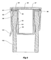
FIG. 1 is a cross-sectional view of a closure according to the preamble of appendedclaim 1 but not within the scope of the present invention when in position on the top of a bottle; -
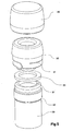
FIG. 2 is an external perspective view as an exploded view of the closure according toFig 1 together with a seal and underneath a representation of the top of the bottle; -
FIG. 3 is another bottle closure according to the preamble of appendedclaim 1 but not within the scope of the present invention where the cross-sectional view, in this case, is again of the closure when in position on the top of a bottle and holding a seal under pressure with the addition, however, of an external cap; -
FIG. 4 is the same view as inFIG. 3 except, in this case, the cap is lifted relative to a closure; -
FIG. 5 is an external perspective view of the elements as inFig 3 exploded, together with a representation of the top of a bottle at the bottom; -
FiG. 6 is a cross sectional view of a first embodiment of the invention as positioned in a sealing position on the top of the bottle with an additional sealing member held between the two walls providing an inwardly projecting portion; -
FIG. 7 is a cross sectional view of a second embodiment also in a closing position on the top of the bottle; -
FIG. 8 is a cross sectional view of a third embodiment also again shown in a closing position on the top of the bottle; -
FIG. 9 is a cross sectional view of a fourth embodiment. - Now referring to the drawings in details and, In particular, the bottle closure of another type than the present invention as illustrated In
FIGS. 1 and2 . - In this case there is a
closure 1, which is, in this case, shown as closing amouth 2 of abottle 3. - The bottle is made of glass and has an external outwardly extending
integral collar 4 which extends fully around an outside of the neck of the bottle and is of a constant shape and size at any location around the periphery. - This is a conventional feature of a number of existing bottles but is in distinction of a screw thread shape, which is the requirement for a "Stelvin" type closure.
- There is a
seal 5 held under compression against anuppermost rim 6 of thebottle mouth 2 andsurface 7, which is adapted to engage with compression force theseal 5. - There is a
portion 8,which is located within the mouth of thebottle 3. - This portion includes a
bulbous section 9 which is provided by a thin wall section of plastics material given that the closure generally is made from plastics material, such that when the thin wall of thebulbous section 9 is compressed as when it passes through thenarrower section 10 of thebottle 3, then it will Internally compress and effect sufficient compression to effect a sealing with the Inner sides of the bottle neck during an extraction process. A "popping" sound is achieved by having the position of the seal somewhat below the mouth prior to extraction so that there will be upon extraction an evacuation of the headspace within the bottle. The depth of the bulbous portion in this embodiment is approximately 25 millimeters. - This sealing effect will also conventionally apply when the
portion 8 is inserted within themouth 2 but it will depend upon the tolerance of theinner surface 11 of the bottle mouth so that if this is a little larger, then as shown in the drawings, there might not be contact during storage although when it is extracted, there will be this sealing to effect a "popping" sound. - The shape of the thin wall
bulbous section 9 is shown, so as to be supported by acylindrical part 12 and an arcuate portion, which together then defines aconcave area 14. - An
outer surround 15 engages with interlocking fit by having an inwardly extendinglip 16, the outwardly extendinglowermost step 17 of thecollar 4. - In this way, by insertion of the
closure 1 over the bottle mouth, this will be inserted to the extent that there is caused this interlocking fit and the tolerance of theseal 5 is such that this will be caused to effect the seal by reason of this extent of compression. - For removal of the closure from a bottle, there is provided a detachable strip shown at 18, which is secured to a remainder of the body of the
closure 1 by a weakened portion at 19 which substantially surrounds, but not totally, thesurround 15. - An
extended tab 20 provides for a first location and pull tab position which then assists in a consumer sufficiently removing this tear off tab portion so that there will be either negligible or no resistance to then subsequent removal by reason of any interlocking fit. - Such a tearable strip shall be attached to the main body of the closure with sufficient strength so that it will be able to retain the
seal 5 under compression over a substantial period of time. - However, it will be sufficiently tearable so that even a relatively weak adult may be able to adequately grasp the pull off tear tag and pull this away to release the closure from an interlocking fit.
- There are techniques known to provide such a characteristic and with experiment, this can be achieved with this particular example.
- The body is intended to be manufactured by injection moulding from plastics material where the plastics material, being in contact with product within a bottle will be of a food grade character.
- A characteristic of this closure is that then there is provided a snap-on closure, which then provides a very substantive sealing effect while also providing a "popping" sound when being removed.
- in relation to the closure of
Fig 3-5 , the purpose for this is to provide a cap that will cover the closure but which can be lifted to expose the tear away tab. - Accordingly, the functional features of the bottle shown at 30 including a
mouth 31 and an Inner engagedsurface 32, acompression seal 33 and aplastics body 34 are the same as in the first embodiment. - The difference, however, is that there is a further outstanding step at 35 which firstly is adapted to act with Inwardly extending
protrudence 36 and inwardly extendingstep 37. - There is further an inward projection at 38, which fills the
cavity 39, which is the same cavity as shown In the first embodiment. - The advantage of this arrangement now is that the
cap 40 can be made in any decorative form and support any labeling and is such that when theclosure 34 is to be accessed for removal, a first step is to lift thecap 40 to a position as is shown InFIG. 4 fromFIG. 3 . - This then exposes the tear away tab and
strip 41, which is effectively interengaging with thestep 42 to provide an interlocking fit and hold down the compression seal. - While the cap, in this case, is shown with a level top, this can include extended tops or any decorative finish appropriate to the application but also to enable quick recognition of a particular brand where the extension may be in the form of a particularly well-recognized logo.
- This cap conventionally would also be manufactured from plastics material by Injection moulding.
- Now referring to the first embodiment, the difference here is that there is an
Inwardly projecting part 50 which is integrally moulded as part of thetotal body 51 where there is also anouter surround 52 which is intended to be located on top of thebottle 53 by engagement of an Inwardly directly step 54 to hold thebody 51 in such a closing position. - One of the features of this arrangement is that there is additional resiliency within an
annular wad 55 which holds a material, in this case analuminium foil 56 with anouter coating 57 of appropriate plastics material against the uppermost rim of the mouth of thebottle 53. - However, this would ordinarily therefore leave access to gas within the
space 59 to allow possible permeation of the body of the plastics material at 60. - In order to ensure that the closure provides an additional seal against the gas passage such as for instance oxygen, there is inserted in this case then a substantially non
permeable sheet 61 which is held by friction between the downwardly projectingwall 50 where there is also alowermost coating surface 62 and an uppermost foam material providing additional resiliency at 63. - This still leaves some possible permeability through the
thin wall 50 through the vertical passage for gas through this wall although this would be no where near as permeable as the otherwise open area of the top of the body at 60. - Accordingly, there is advantage in a further arrangement, which is shown In the second embodiment,
figure 7 . - In this case, the
body 70 is assembled from previously separable parts and there is an inwardly projectingpart 71, a top 72 and an outwardly extendingsurrounding part 73. - This outwardly surrounding
part 73 also includes a tear awayportion 74 which Includes sufficient part of the inwardly directed step at 75 so that when the tear away part is torn away, this will allow at least reasonable removal of thebody 70 from the closing position as shown. - In this case then the
bottle 76 has its upper most mouth defined by the tops at 77 but in this case, there is a substantiallyresilient wad 78 which extends fully fromside 79 toside 80 and has In front of it thesheet 81 which is made from an Impermeable metal In this case aluminium, and there Is an underneath plastics coating, In this case PVDC, on this at 82. - The problem faced here however Is that all of these members need to be able to be joined together In a way that will not therefore substantively prejudice the sealing quality of the
metal sheet 81, but at the same time be able to be Incorporated economically. - In this case, there is provided a
staple 83, which is passed through a transversetop part 84 of the downwardly projectingpart 71 and the staple has its ends outwardly turned at 85. - This then ensures that all of the components are held together and where the staple passes through the metal of the
gas barrier material 81, this would be expected to be a very tight fit and as such allow for only very minimal gas passage thereby. - As with the other cases, the downwardly projecting
part 71 includes a lowermostbulbous part 86, which allows for a resilient bearing surface. - This embodiment therefore again as with others combines both the possibility of location of the cap simply with a snap on fit and by having the necessity of a tear away strip to allow removal, therefore provides a snap-on tamper evident (SOTE) or a snap-on pilfer proof (SOPP) closure, which together provides effective sealing to a level which is similar to that provided by such closures as the roll-on tamper evident (ROTE) or the roil-on pilfer proof (ROPP) saew-cap closures, such as the "Stelvin" closure.
- Now referring to the third embodiment as shown in
figure 8 , the seal in this case is effected by having a continuous sheet at 90 which being circular is welded at its periphery shown at 91 to a furtherannular sheet 92. - This join 91 is such that this forms a gas resistant join and in this case the centrally projecting portion at 93 is co-moulded so that there is a soft resilient part at 95 and a
harder part 94. - Otherwise, this closure, which Is generally shown at 96, includes a
body 97, which includes an Inwardly directed step at 98 so as to support the downwardly projectingpart 93 and at the same time hold together the metal sheets with respect to thetop rim 99 of thebottle top 100. - This embodiment further includes the other features described in the other embodiments which is to say a tear away strip such as at 101 which allows for subsequent removal of the
body 97 from inter engagement with the outwardly directedstep 102 of thebottle top 100. - Now referring to the fourth embodiment, as shown in
figure 9 , which has a further sealing arrangement. - In this case, the
body 110 is adhering to a further integrally mouldedpart 111, which has supported therewith a downwardly projectingportion 112, which includes a lowermostbulbous portion 113, which extends into the bottle, as is the case with all of the other Instances. - The advantage of this extension is that it does assist in providing a somewhat similar extraction of any air or gas within the top of the bottle so as it is released, there is a "popping" sound similar to that provided when a cork is pulled out.
- In this case, there is a gas resistant sheet at 115 where the plastics material of this
part 111 passes throughaperture 116 in one instance and 117 In the other. - This again then has a resilient upper surface material at 118 which therefore allows firstly for the cap when pushed onto the top of the
bottle 119 to be pushed past an interlocking position with the Inwardly directedstep 120 interlocking with the outwardly directed step of thebottle 119, namely 121, where after the resiliency of thematerial 118 will then re-assert a sealing pressure and maintain this sealing effect so as to resist a build up of pressure in the vacuity (headspace) between the closure and the wine. - Throughout this specification there has now been described both a simple apparatus and a more complex apparatus In various embodiments, which in each case provides for a centrally projected part which projects substantially Into the top of the bottle.
- One of the features of the arrangement described is that in each case they are appropriate to be used in conjunction with a capsule. Such capsules are conventionally used in the wine industry although not exclusively and maybe of lead, aluminium or more recently extruded sheet plastics material. Where these are used in conjunction with the tear away strip it is of advantage that access to this can either be visually seen or can be available through an aperture through the capsule.
- In consideration of the slightly wider shape provided by the outer surround in this invention, a capsule should be able to be constrained beneath the closure so that for instance, if a plastics material were used for the capsule, a shrink wrap effect could be used. Alternatively, with metal foil, this could be rolled into the more compact location around a bottleneck.
- An application for these closures is predominantly for materials such as wine where there is value in the celebratory aspect of the material and its access.
Claims (21)
- A bottle closure where the bottle (53) is of a type having a mouth (2) to be closed, the closure having a body (51) having an outer surround (52) adapted to engage, with an interlocking fit, an outwardly extending integral cottar of the neck of the bottle, a seal (57) adapted to be held under compression by the body against an uppermost rim (58) of the bottle mouth, and a portion (50) of the body adapted to be located within the mouth of the bottle and, at least during extraction, to effect a seal with an inner surface of the mouth of the bottle, the interlocking fit being effected by an inwardly directed lip adapted to engage a lower edge of an integral collar of the bottle, the seal being comprised of at least in part a material providing substantial resistance to the passage of oxygen there through, characterized in that the seal (57, 61) is of a form and positioned as a part of the closure such that it extends substantially across the mouth of the bottle when the closure is in a closure position in respect of a bottle so as to provide thereby at least substantial resistance of gas passage there past or there through.
- A bottle closure according to claim 1 further characterized in that the body is comprised of at least two parts (71-73) which are assembled together with the seal held between the two parts where one of the parts is comprising the portion of the body adapted to be located within the mouth of the bottle.
- A bottle closure as in claim 2 further characterized in that the body is an assembly where the portion (71) of the body adapted to be located within the mouth of the bottle is attached to a portion (72) of the body by connecting means (83).
- A bottle closure as in claim 2 further characterized in that the two parts (71-73) are joined by a metal means (83) projecting mutually through the respective parts.
- A bottle closure as in any one of the preceding claims 2 or 3 further characterized in that the two parts are joined by at least one finger of plastics material extending through the seal.
- A bottle closure as in claim 1 further characterized in that the Inwardly directed lip is attached to a remainder of the body such that the lip can be manually separated from the remainder of the body whereby to reduce the interlocking effect to allow for subsequent removal of the closure from a closure position in relation to a bottle.
- A bottle closure as in preceding claim 6 further characterized in that the inwardly directed lip is provided by a tear away strip.
- A bottle closure in any one of the preceding claims characterized in that it creates a liquid seal upon reinsertion of said closure in the bottle mouth of said bottle.
- A bottle closure as in any one of the preceding claims further characterized in that the inner portion of the body provides an outer surface which is provided by a thin wall such that there can be effected substantial resilience to maintain a closure, to afford, upon being withdrawn, a sealing engagement with the inner surface of the mouth of the bottle thereby.
- A bottle closure as in preceding claim 2 further characterized in that the two parts (71-73) are joined by a metal staple (83).
- A bottle closure as in claim 1 further characterized in that the closure has the body providing an outer surround and a projecting portion of the body adapted to be located projecting substantially into the mouth of the bottle moulded as integral one with the other.
- A bottle closure as in any one of the preceding claims further characterized in that the portion adapted to be located within the mouth of a bottle is of a shape where there is a bulbous end provided by a thin wall of plastics material.
- A bottle closure as in preceding claim 12, further characterized in that there is further included a gas resistant sealing material extending between a wall defining an upper end of the portion adapted to be located within the mouth of a bottle.
- A bottle closure as in any one of the preceding claims further characterized in that the portion adapted to be located within the mouth of a bottle is of a shape and length such that when extracted from a selected bottle with a selected quantity of liquid in the bottle that it can be expected to provide a popping sound.
- A bottle closure as in any one of the preceding claims further characterized in that the body is made from injection moulded plastics material.
- A bottle closure as in any one of the preceding claims further characterized in that there is included a further member including a projecting portion extending into an inner portion of the body so as to be supported thereby and including a further part or parts providing visually attractive features.
- A combination of a bottle and a closure according to any of the preceding claims when in a closing position with respect to the mouth of the bottle.
- The combination of a bottle and a closure according to claim 17 further characterised in that said closure covered by a capsule.
- A method of closure of a bottle which includes the steps of inserting a closure according to any one of the above claims 1-16, into a bottle Including forcing the inwardly directed lip to ride over and behind the edge of the Integral collar and being arranged so that this will, in this position, effect substantive compression of a seal between the body of the closure and an uppermost edge of the rim of the bottle.
- A method as in preceding claim 19 further characterized in that the body includes means adapted to receive a further member.
- method as in preceding claim 20 further characterized in that such a further member includes a projecting portion extending Into an Inner portion of the body so as to be supported thereby and including a further part or parts providing visually attractive features.
Applications Claiming Priority (3)
| Application Number | Priority Date | Filing Date | Title |
|---|---|---|---|
| AU2002000532 | 2002-02-15 | ||
| AUPS0532A AUPS053202A0 (en) | 2002-02-15 | 2002-02-15 | Closure |
| PCT/AU2003/000189 WO2003068622A1 (en) | 2002-02-15 | 2003-02-17 | Synthetic bottle closure |
Publications (3)
| Publication Number | Publication Date |
|---|---|
| EP1494934A1 EP1494934A1 (en) | 2005-01-12 |
| EP1494934A4 EP1494934A4 (en) | 2005-05-11 |
| EP1494934B1 true EP1494934B1 (en) | 2008-07-16 |
Family
ID=3834132
Family Applications (1)
| Application Number | Title | Priority Date | Filing Date |
|---|---|---|---|
| EP03701357A Expired - Lifetime EP1494934B1 (en) | 2002-02-15 | 2003-02-17 | Synthetic bottle closure |
Country Status (13)
| Country | Link |
|---|---|
| US (2) | US20050284839A1 (en) |
| EP (1) | EP1494934B1 (en) |
| CN (1) | CN100349784C (en) |
| AR (1) | AR038558A1 (en) |
| AT (1) | ATE401253T1 (en) |
| AU (1) | AUPS053202A0 (en) |
| CA (1) | CA2479390A1 (en) |
| DE (1) | DE60322201D1 (en) |
| ES (1) | ES2310648T3 (en) |
| NZ (1) | NZ535327A (en) |
| PT (1) | PT1494934E (en) |
| WO (1) | WO2003068622A1 (en) |
| ZA (1) | ZA200407402B (en) |
Families Citing this family (21)
| Publication number | Priority date | Publication date | Assignee | Title |
|---|---|---|---|---|
| US20090032488A1 (en) * | 2007-07-30 | 2009-02-05 | Owens-Illinois Closure Inc. | Ceremonial plug closure and package |
| CN101607615A (en) * | 2008-06-20 | 2009-12-23 | 栓乐多瓶塞有限公司 | Air pressure type corking cover |
| EP2408571B1 (en) * | 2009-03-17 | 2015-09-16 | Boehringer Ingelheim International GmbH | Reservoir and atomizer |
| USD678768S1 (en) | 2011-06-16 | 2013-03-26 | AGAM Innovations Ltd. | Sealable pourer |
| SG190764A1 (en) * | 2010-10-08 | 2013-07-31 | Or Agassi | A sealable pourer |
| US9714123B2 (en) | 2010-10-08 | 2017-07-25 | AGAM Innovations Ltd. | Dispensing closure |
| US8944297B2 (en) | 2010-10-08 | 2015-02-03 | AGAM Innovations Ltd. | Sealable pourer |
| WO2013004855A1 (en) * | 2011-07-06 | 2013-01-10 | Termometros Y Exclusivas, S.L. | Silicone stopper for cavabottles and the like |
| EP2592015A1 (en) | 2011-11-09 | 2013-05-15 | Carlsberg Breweries A/S | Beverage bottle with a re-sealable closure having a cap and a collar |
| AU2013217001A1 (en) * | 2012-02-07 | 2014-08-28 | Plastipak Packaging, Inc. | Container seal closure and assembly |
| US10407222B2 (en) * | 2012-02-16 | 2019-09-10 | David O. Allen | Container and closure assembly |
| FR2996543B1 (en) | 2012-10-05 | 2015-05-29 | Qualipac Sa | METHOD FOR ASSEMBLING A PACKING DEVICE |
| USD738213S1 (en) | 2014-02-18 | 2015-09-08 | AGAM Innovations Ltd. | Pourer |
| USD792766S1 (en) | 2014-05-15 | 2017-07-25 | AGAM Innovations Ltd. | Pourer |
| ES2795777T3 (en) | 2015-03-05 | 2020-11-24 | Aptargroup Inc | Annex and cover for the same |
| CN111315660A (en) | 2017-11-09 | 2020-06-19 | 唯万盛美国有限责任公司 | Method for producing a closure for a product-retaining container |
| CN111315564B (en) * | 2017-11-09 | 2023-04-04 | 唯万盛美国有限责任公司 | Method for producing a closure for a product-retaining container |
| RU191176U1 (en) * | 2018-10-20 | 2019-07-29 | Анастасия Ринатовна Насибуллина | Sealing gasket |
| WO2020237007A1 (en) | 2019-05-23 | 2020-11-26 | Ecolab Usa Inc. | Dispensing system |
| EP4120134A1 (en) * | 2021-07-15 | 2023-01-18 | Les Bouchages Delage | Method for manufacturing a bottle cap including an rfid tag and plug |
| CN115180297B (en) * | 2022-09-13 | 2022-12-06 | 烟台市永盛密封科技有限公司 | Combined aluminum foil easy to seal |
Family Cites Families (46)
| Publication number | Priority date | Publication date | Assignee | Title |
|---|---|---|---|---|
| US371771A (en) * | 1887-10-18 | Chaeles von dee linden | ||
| US1112875A (en) * | 1913-10-31 | 1914-10-06 | Patrick John Whelan | Cork extractor and fastener. |
| US1747760A (en) * | 1927-09-19 | 1930-02-18 | James U Duffy | Bottle cap and cork |
| US2666542A (en) * | 1948-05-24 | 1954-01-19 | Charles S Price | Adhesive metal foil, bottle cap thereof, and method |
| US2940629A (en) * | 1957-05-04 | 1960-06-14 | Cros Modesto | Container sealing system |
| US3128896A (en) * | 1961-02-20 | 1964-04-14 | Robert F Schnier | Bottle closure |
| US3245569A (en) * | 1964-08-17 | 1966-04-12 | Essich Helmut | Bottle stopper arrangement |
| US3831798A (en) * | 1972-07-18 | 1974-08-27 | Dorn Co V | Container sealing lid |
| IT1000576B (en) * | 1974-01-08 | 1976-04-10 | Fiscem Spa | CLOSURE FOR PART CONTAINERS FOR BOTTLES AND BOTTLES |
| DE2414667A1 (en) * | 1974-03-27 | 1975-10-09 | Hans Voelker | CAPS FOR BOTTLES, IN PARTICULAR WINE AND CHAMPAGNE BOTTLES |
| US3940005A (en) * | 1974-04-11 | 1976-02-24 | A.C.I. Operations Pty. Limited | Safety closure means for pressurized bottles and other like containers |
| FR2271134A1 (en) * | 1974-05-17 | 1975-12-12 | Bouchage Mecanique | Pilfer proof closure for bottle with plain neck - has non-drip pourer and stopper in bottle neck and foil cover with tear off strip |
| US3946891A (en) * | 1975-04-07 | 1976-03-30 | Picoy Anthony R | Safety cap for pressurized bottles |
| US4109816A (en) * | 1976-11-01 | 1978-08-29 | Three Sisters Ranch Enterprise | Plastic cap for bottle |
| US4166552A (en) * | 1977-11-16 | 1979-09-04 | Three Sisters Ranch Enterprises | Plastic cap and container construction |
| US4342400A (en) * | 1980-09-10 | 1982-08-03 | Precision Plastic Products Corp. | Tamper indicating closure and pressurized container |
| US4363416A (en) * | 1981-07-15 | 1982-12-14 | Apm, Inc. | Wine cork |
| GB8427911D0 (en) * | 1984-11-05 | 1984-12-12 | Evans T G | Screw-topped containers |
| US4650083A (en) * | 1985-06-06 | 1987-03-17 | William Lembeck | Safety closure for use in conjunction with bottling of champagne and other sparkling wines |
| US4804099A (en) * | 1987-10-28 | 1989-02-14 | Chuan Chang C | Bottle closure system |
| DE68903023T2 (en) * | 1988-04-18 | 1995-10-19 | Capsulit Srl | Closure for disposable bottles and the like, containing a container with a bottom that can be pierced. |
| US4809871A (en) * | 1988-05-02 | 1989-03-07 | Angelchik Jean P | Closure for sealing an aperture |
| US4889251A (en) * | 1988-07-28 | 1989-12-26 | Hojnoski David E | Cork stopper for bottles of wine |
| US4896782A (en) * | 1989-02-13 | 1990-01-30 | Sunbeam Plastics Corporation | Closure with insert for enhanced sealing |
| DE3930519A1 (en) * | 1989-09-13 | 1991-03-21 | Bayer Ag | CONTAINER WITH SCREW CAP |
| DE3940461A1 (en) * | 1989-12-07 | 1991-06-13 | Pfefferkorn & Co | Plastic stopper for e.g. wine bottles - consist of e.g. foam body in two halves joined together by horizontal gas barrier of e.g. foil coated each side with polyethylene |
| DE4016592C1 (en) * | 1990-01-22 | 1991-05-23 | Knopf, Karl Horst, 5650 Solingen, De | |
| US5109997A (en) * | 1991-06-21 | 1992-05-05 | Phillips Edwin D | Expandable stopper |
| WO1993012980A1 (en) * | 1991-12-30 | 1993-07-08 | Finke Stephan J | Methods and combinations for sealing corked bottles |
| US5261547A (en) * | 1991-12-30 | 1993-11-16 | Finke Stephan J | Methods and combinations for sealing corked bottles |
| DE9390048U1 (en) * | 1992-03-06 | 1993-12-16 | Herrmann Ernst | Closure with guarantee device |
| US5626251A (en) * | 1993-05-07 | 1997-05-06 | Ropak Corporation | Container lid |
| CA2193075C (en) * | 1994-06-16 | 2003-09-23 | David E. Hojnoski | Cork stopper for bottles of wine |
| US5662233A (en) * | 1995-04-12 | 1997-09-02 | Innovative Molding, Inc. | Wine bottle closure |
| FR2744100B1 (en) * | 1996-01-26 | 1998-03-13 | Astra Plastique | PLUG FOR LOCKING ONTO THE NECK OF A CONTAINER |
| AUPO538097A0 (en) * | 1997-02-28 | 1997-03-27 | Rosemount Estates Pty Ltd | Cork transition die |
| IT1292677B1 (en) * | 1997-02-28 | 1999-02-11 | Bormioli Metalplast Spa | PACKAGING TO KEEP THE PRODUCTS SEPARATE BEFORE USE. |
| US5868264A (en) * | 1997-09-18 | 1999-02-09 | Fleming Packaging Corporation | Formed and decorated seal |
| FR2795392B1 (en) * | 1999-06-25 | 2001-08-31 | Lorraine Capsules Metall | CAPPING DEVICE FOR SEALING A BOTTLE CONTAINING A GAS WINE |
| US6168036B1 (en) * | 1999-10-01 | 2001-01-02 | Hsi-Hsiung Teng | Corkscrew-free bottle stopper |
| US6536618B1 (en) * | 2000-10-31 | 2003-03-25 | Hsu-Rong Hwang | Bottle plug |
| US20030057173A1 (en) * | 2001-03-08 | 2003-03-27 | Wagner David C. | Flange screw closure and bottle having internal threads |
| US6719160B2 (en) * | 2001-09-28 | 2004-04-13 | Sunlot Bottle Stopper Co., Ltd. | Bottle stopper |
| US7426999B2 (en) * | 2002-10-15 | 2008-09-23 | Leendersten Howard V | Bottle closure |
| US6772892B2 (en) * | 2002-11-19 | 2004-08-10 | E. & J. Gallo Winery | Reusable closure system for bottle-type containers |
| US20050035081A1 (en) * | 2003-08-12 | 2005-02-17 | Fitch Russell M. | Tamper resistant beverage bottle |
-
2002
- 2002-02-15 AU AUPS0532A patent/AUPS053202A0/en not_active Abandoned
-
2003
- 2003-02-17 ES ES03701357T patent/ES2310648T3/en not_active Expired - Lifetime
- 2003-02-17 PT PT03701357T patent/PT1494934E/en unknown
- 2003-02-17 CA CA002479390A patent/CA2479390A1/en not_active Abandoned
- 2003-02-17 NZ NZ535327A patent/NZ535327A/en not_active IP Right Cessation
- 2003-02-17 US US10/507,626 patent/US20050284839A1/en not_active Abandoned
- 2003-02-17 CN CNB03808354XA patent/CN100349784C/en not_active Expired - Fee Related
- 2003-02-17 AT AT03701357T patent/ATE401253T1/en not_active IP Right Cessation
- 2003-02-17 EP EP03701357A patent/EP1494934B1/en not_active Expired - Lifetime
- 2003-02-17 DE DE60322201T patent/DE60322201D1/en not_active Expired - Lifetime
- 2003-02-17 WO PCT/AU2003/000189 patent/WO2003068622A1/en active IP Right Grant
- 2003-02-18 AR ARP030100521A patent/AR038558A1/en active IP Right Grant
-
2006
- 2006-04-26 ZA ZA200407402A patent/ZA200407402B/en unknown
-
2010
- 2010-10-12 US US12/902,835 patent/US9555933B2/en not_active Expired - Fee Related
Also Published As
| Publication number | Publication date |
|---|---|
| EP1494934A1 (en) | 2005-01-12 |
| US9555933B2 (en) | 2017-01-31 |
| ES2310648T3 (en) | 2009-01-16 |
| ZA200407402B (en) | 2006-06-28 |
| US20110024383A1 (en) | 2011-02-03 |
| DE60322201D1 (en) | 2008-08-28 |
| CN1646387A (en) | 2005-07-27 |
| EP1494934A4 (en) | 2005-05-11 |
| AUPS053202A0 (en) | 2002-03-07 |
| CA2479390A1 (en) | 2003-08-21 |
| WO2003068622A1 (en) | 2003-08-21 |
| PT1494934E (en) | 2008-10-24 |
| US20050284839A1 (en) | 2005-12-29 |
| ATE401253T1 (en) | 2008-08-15 |
| AR038558A1 (en) | 2005-01-19 |
| CN100349784C (en) | 2007-11-21 |
| NZ535327A (en) | 2004-12-24 |
Similar Documents
| Publication | Publication Date | Title |
|---|---|---|
| US9555933B2 (en) | Synthetic bottle closure | |
| US11891208B2 (en) | Apparatus to seal a metallic container | |
| AU660216B2 (en) | Cork | |
| US9868564B2 (en) | Metal container | |
| CN101528381B (en) | Method for producing such a metal closure with separate disc and ring from a single closure blank | |
| US20100012615A1 (en) | Bottle Closure with Two Interlocking Parts One Fitting Over the Other | |
| US3622028A (en) | Closure construction | |
| US4506797A (en) | Wine bottle cover | |
| US4369889A (en) | Tamperproof closure | |
| US3292807A (en) | Tamper-proof closure | |
| US20050056612A1 (en) | Systems, devices and methods for opening a bottle sealed with a stopper and for sealing a bottle | |
| US20090101661A1 (en) | Can container | |
| US20040031770A1 (en) | Systems, devices and methods for opening a bottle sealed with a stopper and for sealing a bottle | |
| US20040232102A1 (en) | Systems, devices and methods for opening a bottle sealed with a stopper and for sealing a bottle | |
| JPS6121354A (en) | Combination of vessel having explosion-proof characteristic and vessel cover | |
| AU2003203053B2 (en) | Synthetic bottle closure | |
| US6772892B2 (en) | Reusable closure system for bottle-type containers | |
| WO2006026803A1 (en) | An improved closure, a method of forming thereof and a method of sealing and/or closing a bottle | |
| AU626656B2 (en) | Plastic closure and method of manufacture | |
| AU2003247398A1 (en) | Systems, devices and methods for opening a bottle sealed with a stopper and for sealing a bottle | |
| WO2004058586A1 (en) | Bottle closure | |
| JPH04115147U (en) | sealed cap | |
| JP2004331190A (en) | Container lid having inner pressure releasing characteristic | |
| JP4374240B2 (en) | Products containing container lids and carbon dioxide beverages using the same |
Legal Events
| Date | Code | Title | Description |
|---|---|---|---|
| PUAI | Public reference made under article 153(3) epc to a published international application that has entered the european phase |
Free format text: ORIGINAL CODE: 0009012 |
|
| 17P | Request for examination filed |
Effective date: 20040915 |
|
| AK | Designated contracting states |
Kind code of ref document: A1 Designated state(s): AT BE BG CH CY CZ DE DK EE ES FI FR GB GR HU IE IT LI LU MC NL PT SE SI SK TR |
|
| AX | Request for extension of the european patent |
Extension state: AL LT LV MK RO |
|
| A4 | Supplementary search report drawn up and despatched |
Effective date: 20050330 |
|
| 17Q | First examination report despatched |
Effective date: 20060323 |
|
| 17Q | First examination report despatched |
Effective date: 20060323 |
|
| GRAP | Despatch of communication of intention to grant a patent |
Free format text: ORIGINAL CODE: EPIDOSNIGR1 |
|
| GRAS | Grant fee paid |
Free format text: ORIGINAL CODE: EPIDOSNIGR3 |
|
| GRAA | (expected) grant |
Free format text: ORIGINAL CODE: 0009210 |
|
| AK | Designated contracting states |
Kind code of ref document: B1 Designated state(s): AT BE BG CH CY CZ DE DK EE ES FI FR GB GR HU IE IT LI LU MC NL PT SE SI SK TR |
|
| REG | Reference to a national code |
Ref country code: GB Ref legal event code: FG4D |
|
| REG | Reference to a national code |
Ref country code: CH Ref legal event code: EP |
|
| REF | Corresponds to: |
Ref document number: 60322201 Country of ref document: DE Date of ref document: 20080828 Kind code of ref document: P |
|
| REG | Reference to a national code |
Ref country code: IE Ref legal event code: FG4D |
|
| REG | Reference to a national code |
Ref country code: PT Ref legal event code: SC4A Free format text: AVAILABILITY OF NATIONAL TRANSLATION Effective date: 20081014 |
|
| NLV1 | Nl: lapsed or annulled due to failure to fulfill the requirements of art. 29p and 29m of the patents act | ||
| REG | Reference to a national code |
Ref country code: ES Ref legal event code: FG2A Ref document number: 2310648 Country of ref document: ES Kind code of ref document: T3 |
|
| PG25 | Lapsed in a contracting state [announced via postgrant information from national office to epo] |
Ref country code: NL Free format text: LAPSE BECAUSE OF FAILURE TO SUBMIT A TRANSLATION OF THE DESCRIPTION OR TO PAY THE FEE WITHIN THE PRESCRIBED TIME-LIMIT Effective date: 20080716 |
|
| PG25 | Lapsed in a contracting state [announced via postgrant information from national office to epo] |
Ref country code: SI Free format text: LAPSE BECAUSE OF FAILURE TO SUBMIT A TRANSLATION OF THE DESCRIPTION OR TO PAY THE FEE WITHIN THE PRESCRIBED TIME-LIMIT Effective date: 20080716 Ref country code: FI Free format text: LAPSE BECAUSE OF FAILURE TO SUBMIT A TRANSLATION OF THE DESCRIPTION OR TO PAY THE FEE WITHIN THE PRESCRIBED TIME-LIMIT Effective date: 20080716 Ref country code: AT Free format text: LAPSE BECAUSE OF FAILURE TO SUBMIT A TRANSLATION OF THE DESCRIPTION OR TO PAY THE FEE WITHIN THE PRESCRIBED TIME-LIMIT Effective date: 20080716 Ref country code: BG Free format text: LAPSE BECAUSE OF FAILURE TO SUBMIT A TRANSLATION OF THE DESCRIPTION OR TO PAY THE FEE WITHIN THE PRESCRIBED TIME-LIMIT Effective date: 20081016 |
|
| PG25 | Lapsed in a contracting state [announced via postgrant information from national office to epo] |
Ref country code: BE Free format text: LAPSE BECAUSE OF FAILURE TO SUBMIT A TRANSLATION OF THE DESCRIPTION OR TO PAY THE FEE WITHIN THE PRESCRIBED TIME-LIMIT Effective date: 20080716 |
|
| PG25 | Lapsed in a contracting state [announced via postgrant information from national office to epo] |
Ref country code: EE Free format text: LAPSE BECAUSE OF FAILURE TO SUBMIT A TRANSLATION OF THE DESCRIPTION OR TO PAY THE FEE WITHIN THE PRESCRIBED TIME-LIMIT Effective date: 20080716 Ref country code: DK Free format text: LAPSE BECAUSE OF FAILURE TO SUBMIT A TRANSLATION OF THE DESCRIPTION OR TO PAY THE FEE WITHIN THE PRESCRIBED TIME-LIMIT Effective date: 20080716 |
|
| PLBE | No opposition filed within time limit |
Free format text: ORIGINAL CODE: 0009261 |
|
| STAA | Information on the status of an ep patent application or granted ep patent |
Free format text: STATUS: NO OPPOSITION FILED WITHIN TIME LIMIT |
|
| PG25 | Lapsed in a contracting state [announced via postgrant information from national office to epo] |
Ref country code: CZ Free format text: LAPSE BECAUSE OF FAILURE TO SUBMIT A TRANSLATION OF THE DESCRIPTION OR TO PAY THE FEE WITHIN THE PRESCRIBED TIME-LIMIT Effective date: 20080716 Ref country code: SK Free format text: LAPSE BECAUSE OF FAILURE TO SUBMIT A TRANSLATION OF THE DESCRIPTION OR TO PAY THE FEE WITHIN THE PRESCRIBED TIME-LIMIT Effective date: 20080716 |
|
| 26N | No opposition filed |
Effective date: 20090417 |
|
| PG25 | Lapsed in a contracting state [announced via postgrant information from national office to epo] |
Ref country code: MC Free format text: LAPSE BECAUSE OF NON-PAYMENT OF DUE FEES Effective date: 20090228 |
|
| REG | Reference to a national code |
Ref country code: CH Ref legal event code: PL |
|
| PG25 | Lapsed in a contracting state [announced via postgrant information from national office to epo] |
Ref country code: LI Free format text: LAPSE BECAUSE OF NON-PAYMENT OF DUE FEES Effective date: 20090228 Ref country code: CH Free format text: LAPSE BECAUSE OF NON-PAYMENT OF DUE FEES Effective date: 20090228 |
|
| REG | Reference to a national code |
Ref country code: IE Ref legal event code: MM4A |
|
| PG25 | Lapsed in a contracting state [announced via postgrant information from national office to epo] |
Ref country code: SE Free format text: LAPSE BECAUSE OF FAILURE TO SUBMIT A TRANSLATION OF THE DESCRIPTION OR TO PAY THE FEE WITHIN THE PRESCRIBED TIME-LIMIT Effective date: 20081016 Ref country code: IE Free format text: LAPSE BECAUSE OF NON-PAYMENT OF DUE FEES Effective date: 20090217 |
|
| PG25 | Lapsed in a contracting state [announced via postgrant information from national office to epo] |
Ref country code: GR Free format text: LAPSE BECAUSE OF FAILURE TO SUBMIT A TRANSLATION OF THE DESCRIPTION OR TO PAY THE FEE WITHIN THE PRESCRIBED TIME-LIMIT Effective date: 20081017 |
|
| PG25 | Lapsed in a contracting state [announced via postgrant information from national office to epo] |
Ref country code: LU Free format text: LAPSE BECAUSE OF NON-PAYMENT OF DUE FEES Effective date: 20090217 |
|
| PG25 | Lapsed in a contracting state [announced via postgrant information from national office to epo] |
Ref country code: HU Free format text: LAPSE BECAUSE OF FAILURE TO SUBMIT A TRANSLATION OF THE DESCRIPTION OR TO PAY THE FEE WITHIN THE PRESCRIBED TIME-LIMIT Effective date: 20090117 |
|
| PG25 | Lapsed in a contracting state [announced via postgrant information from national office to epo] |
Ref country code: TR Free format text: LAPSE BECAUSE OF FAILURE TO SUBMIT A TRANSLATION OF THE DESCRIPTION OR TO PAY THE FEE WITHIN THE PRESCRIBED TIME-LIMIT Effective date: 20080716 |
|
| PG25 | Lapsed in a contracting state [announced via postgrant information from national office to epo] |
Ref country code: CY Free format text: LAPSE BECAUSE OF FAILURE TO SUBMIT A TRANSLATION OF THE DESCRIPTION OR TO PAY THE FEE WITHIN THE PRESCRIBED TIME-LIMIT Effective date: 20080716 |
|
| REG | Reference to a national code |
Ref country code: PT Ref legal event code: PC4A Owner name: SCHOLLE INDUSTRIES PTY LTD, AU Effective date: 20120516 Ref country code: PT Ref legal event code: PC4A Owner name: SCHOLLE CORPORATION, US Effective date: 20120516 |
|
| REG | Reference to a national code |
Ref country code: GB Ref legal event code: 732E Free format text: REGISTERED BETWEEN 20120524 AND 20120530 |
|
| REG | Reference to a national code |
Ref country code: DE Ref legal event code: R081 Ref document number: 60322201 Country of ref document: DE Owner name: SCHOLLE CORP., IRVINE, US Free format text: FORMER OWNER: ZORK PTY. LTD., ADELAIDE, SOUTH AUSTRALIA, AU Effective date: 20120516 Ref country code: DE Ref legal event code: R082 Ref document number: 60322201 Country of ref document: DE Representative=s name: MANITZ, FINSTERWALD & PARTNER GBR, DE Effective date: 20120516 Ref country code: DE Ref legal event code: R081 Ref document number: 60322201 Country of ref document: DE Owner name: SCHOLLE CORP., US Free format text: FORMER OWNER: ZORK PTY. LTD., ADELAIDE, AU Effective date: 20120516 Ref country code: DE Ref legal event code: R082 Ref document number: 60322201 Country of ref document: DE Representative=s name: MANITZ FINSTERWALD PATENTANWAELTE PARTMBB, DE Effective date: 20120516 |
|
| REG | Reference to a national code |
Ref country code: FR Ref legal event code: TP Owner name: SCHOLLE CORPORATION, US Effective date: 20120717 |
|
| REG | Reference to a national code |
Ref country code: GB Ref legal event code: 732E Free format text: REGISTERED BETWEEN 20120802 AND 20120808 |
|
| REG | Reference to a national code |
Ref country code: GB Ref legal event code: 732E Free format text: REGISTERED BETWEEN 20120809 AND 20120815 |
|
| REG | Reference to a national code |
Ref country code: ES Ref legal event code: PC2A Owner name: SCHOLLE CORPORATION Effective date: 20131125 |
|
| PGFP | Annual fee paid to national office [announced via postgrant information from national office to epo] |
Ref country code: PT Payment date: 20150217 Year of fee payment: 13 Ref country code: ES Payment date: 20150113 Year of fee payment: 13 |
|
| REG | Reference to a national code |
Ref country code: FR Ref legal event code: PLFP Year of fee payment: 14 |
|
| PG25 | Lapsed in a contracting state [announced via postgrant information from national office to epo] |
Ref country code: PT Free format text: LAPSE BECAUSE OF NON-PAYMENT OF DUE FEES Effective date: 20160817 |
|
| REG | Reference to a national code |
Ref country code: FR Ref legal event code: PLFP Year of fee payment: 15 |
|
| PG25 | Lapsed in a contracting state [announced via postgrant information from national office to epo] |
Ref country code: ES Free format text: LAPSE BECAUSE OF NON-PAYMENT OF DUE FEES Effective date: 20160218 |
|
| REG | Reference to a national code |
Ref country code: FR Ref legal event code: PLFP Year of fee payment: 16 |
|
| PGFP | Annual fee paid to national office [announced via postgrant information from national office to epo] |
Ref country code: GB Payment date: 20180125 Year of fee payment: 16 Ref country code: DE Payment date: 20180207 Year of fee payment: 16 |
|
| PGFP | Annual fee paid to national office [announced via postgrant information from national office to epo] |
Ref country code: FR Payment date: 20180118 Year of fee payment: 16 Ref country code: IT Payment date: 20180228 Year of fee payment: 16 |
|
| REG | Reference to a national code |
Ref country code: DE Ref legal event code: R119 Ref document number: 60322201 Country of ref document: DE |
|
| GBPC | Gb: european patent ceased through non-payment of renewal fee |
Effective date: 20190217 |
|
| PG25 | Lapsed in a contracting state [announced via postgrant information from national office to epo] |
Ref country code: DE Free format text: LAPSE BECAUSE OF NON-PAYMENT OF DUE FEES Effective date: 20190903 Ref country code: GB Free format text: LAPSE BECAUSE OF NON-PAYMENT OF DUE FEES Effective date: 20190217 |
|
| PG25 | Lapsed in a contracting state [announced via postgrant information from national office to epo] |
Ref country code: IT Free format text: LAPSE BECAUSE OF NON-PAYMENT OF DUE FEES Effective date: 20190217 Ref country code: FR Free format text: LAPSE BECAUSE OF NON-PAYMENT OF DUE FEES Effective date: 20190228 |