EP1494592B1 - Devices and methods for tissue retraction - Google Patents
Devices and methods for tissue retraction Download PDFInfo
- Publication number
- EP1494592B1 EP1494592B1 EP03746580A EP03746580A EP1494592B1 EP 1494592 B1 EP1494592 B1 EP 1494592B1 EP 03746580 A EP03746580 A EP 03746580A EP 03746580 A EP03746580 A EP 03746580A EP 1494592 B1 EP1494592 B1 EP 1494592B1
- Authority
- EP
- European Patent Office
- Prior art keywords
- retractor
- portions
- working channel
- collar
- proximal end
- Prior art date
- Legal status (The legal status is an assumption and is not a legal conclusion. Google has not performed a legal analysis and makes no representation as to the accuracy of the status listed.)
- Expired - Lifetime
Links
Images


Classifications
-
- A—HUMAN NECESSITIES
- A61—MEDICAL OR VETERINARY SCIENCE; HYGIENE
- A61B—DIAGNOSIS; SURGERY; IDENTIFICATION
- A61B17/00—Surgical instruments, devices or methods, e.g. tourniquets
- A61B17/02—Surgical instruments, devices or methods, e.g. tourniquets for holding wounds open; Tractors
- A61B17/0293—Surgical instruments, devices or methods, e.g. tourniquets for holding wounds open; Tractors with ring member to support retractor elements
-
- A—HUMAN NECESSITIES
- A61—MEDICAL OR VETERINARY SCIENCE; HYGIENE
- A61B—DIAGNOSIS; SURGERY; IDENTIFICATION
- A61B17/00—Surgical instruments, devices or methods, e.g. tourniquets
- A61B17/34—Trocars; Puncturing needles
-
- A—HUMAN NECESSITIES
- A61—MEDICAL OR VETERINARY SCIENCE; HYGIENE
- A61B—DIAGNOSIS; SURGERY; IDENTIFICATION
- A61B1/00—Instruments for performing medical examinations of the interior of cavities or tubes of the body by visual or photographical inspection, e.g. endoscopes; Illuminating arrangements therefor
- A61B1/32—Devices for opening or enlarging the visual field, e.g. of a tube of the body
-
- A—HUMAN NECESSITIES
- A61—MEDICAL OR VETERINARY SCIENCE; HYGIENE
- A61B—DIAGNOSIS; SURGERY; IDENTIFICATION
- A61B17/00—Surgical instruments, devices or methods, e.g. tourniquets
- A61B17/02—Surgical instruments, devices or methods, e.g. tourniquets for holding wounds open; Tractors
-
- A—HUMAN NECESSITIES
- A61—MEDICAL OR VETERINARY SCIENCE; HYGIENE
- A61B—DIAGNOSIS; SURGERY; IDENTIFICATION
- A61B17/00—Surgical instruments, devices or methods, e.g. tourniquets
- A61B17/34—Trocars; Puncturing needles
- A61B17/3417—Details of tips or shafts, e.g. grooves, expandable, bendable; Multiple coaxial sliding cannulas, e.g. for dilating
- A61B17/3421—Cannulas
- A61B17/3439—Cannulas with means for changing the inner diameter of the cannula, e.g. expandable
-
- A—HUMAN NECESSITIES
- A61—MEDICAL OR VETERINARY SCIENCE; HYGIENE
- A61B—DIAGNOSIS; SURGERY; IDENTIFICATION
- A61B17/00—Surgical instruments, devices or methods, e.g. tourniquets
- A61B17/02—Surgical instruments, devices or methods, e.g. tourniquets for holding wounds open; Tractors
- A61B17/0206—Surgical instruments, devices or methods, e.g. tourniquets for holding wounds open; Tractors with antagonistic arms as supports for retractor elements
-
- A—HUMAN NECESSITIES
- A61—MEDICAL OR VETERINARY SCIENCE; HYGIENE
- A61B—DIAGNOSIS; SURGERY; IDENTIFICATION
- A61B17/00—Surgical instruments, devices or methods, e.g. tourniquets
- A61B17/00234—Surgical instruments, devices or methods, e.g. tourniquets for minimally invasive surgery
- A61B2017/00238—Type of minimally invasive operation
- A61B2017/00261—Discectomy
-
- A—HUMAN NECESSITIES
- A61—MEDICAL OR VETERINARY SCIENCE; HYGIENE
- A61B—DIAGNOSIS; SURGERY; IDENTIFICATION
- A61B17/00—Surgical instruments, devices or methods, e.g. tourniquets
- A61B17/28—Surgical forceps
- A61B17/2812—Surgical forceps with a single pivotal connection
- A61B17/2833—Locking means
- A61B2017/2837—Locking means with a locking ratchet
Definitions
- first edge 51a of second body 43 is adjacent first edge 32a of first body 23, and second edge 51b of body 43 is adjacent second edge 32b of first body 23.
- First edge 32a resides at least partially in grooved portion 54a
- second edge 32b resides at least partially in grooved portion 52b.
- First edge 32a contacts engagement surface 52a along grooved portion 54a to maintain retractor 20 in its expanded configuration.
- second edge 32b contacts engagement surface 52b in grooved portion 54b to maintain retractor 20 in its expanded configuration.
- the flexible first portion 22 tends to return toward its unexpanded configuration, thus first and second edges 32a, 32b frictionally engage the engagement surfaces extending along each of the grooved portions 54a, 54b. This locks first portion 22 with respect to second portion 42 in the expanded configuration, resisting collapse of the working channel by pressure of the surrounding tissue on first and second portions 22, 42 and facilitating manipulation of retractor 20 in the tissue without collapse of the working channel.
- first and second portion 22, 42 in the expanded configuration are also contemplated.
- second portion 42 can be provided with a ridge or protrusion at each of its opposite edges, and first portion 44 can engage the ridge or protrusion.
- working channel 50 is not completely enclosed.
- the contact surfaces 74a', 74b' and 74c' are located at differing distances from pin 75' to allow the surgeon to select the desired amount of expansion for retractor 20.
- Foot 74' is rotated about pin 75' to select the desired contact surface by orienting the desired contact surface away from contact surface 76a of foot 76.
- contact surface 74a' is selected to provide minimum expansion since it is located closest to pin 75'.
- contact surface 74b' is selected to provide maximum expansion since it is located furthest away from pin 75'.
- Fig. 13a contact surface 74a' is selected to provide minimum expansion since it is located closest to pin 75'.
- contact surface 74b' is selected to provide maximum expansion since it is located furthest away from pin 75'.
- each of the contact surfaces 74a', 74b' and 74c' can correspond to a particular retractor length.
- the depth which expansion instrument 60' extends into the retractor is the same no matter the length of the retractor.
- the first and second portions of a shorter retractor will be separated a greater amount at the depth of feet 74', 76 than will a longer retractor.
- contact surface 74a' can be selected for a longer length retractor
- contact surface 74b' can be selected for a shorter length retractor
- contact surface 74c' can be selected for an intermediate length retractor.
- FIGs. 15a-15c another embodiment expandable retractor 120 is shown with a ratchet and pawl type mechanism at the proximal ends of first portion 122 and second portion 142.
- the ratchet and pawl mechanism maintains retractor 120 in its expanded configuration.
- the provision of a grooved portion and engagement surface is not precluded.
- Collar 328 includes a first contact surface 335a below first extension 358a of collar 348, and a second contact surface 335b below second extension 358b of collar 348.
- Collar 348 includes a first lateral extension 356a that provides a contact surface below first extension 334a of collar 328, and an opposite second lateral extension that provides a contact surface below second extension 334b of collar 328.
Landscapes
- Health & Medical Sciences (AREA)
- Life Sciences & Earth Sciences (AREA)
- Surgery (AREA)
- Molecular Biology (AREA)
- General Health & Medical Sciences (AREA)
- Biomedical Technology (AREA)
- Heart & Thoracic Surgery (AREA)
- Medical Informatics (AREA)
- Nuclear Medicine, Radiotherapy & Molecular Imaging (AREA)
- Animal Behavior & Ethology (AREA)
- Engineering & Computer Science (AREA)
- Public Health (AREA)
- Veterinary Medicine (AREA)
- Pathology (AREA)
- Physics & Mathematics (AREA)
- Biophysics (AREA)
- Optics & Photonics (AREA)
- Radiology & Medical Imaging (AREA)
- Surgical Instruments (AREA)
Abstract
Description
- The present invention relates to devices and instruments for performing percutaneous surgeries.
- Traditional surgical procedures for pathologies located deep within the body can cause significant trauma to the intervening tissues. These open procedures often require a long incision, extensive muscle stripping, prolonged retraction of tissues, denervation and devascularization of tissue. These surgeries can require operating room time of several hours and several weeks of post-operative recovery time due to the use of general anesthesia and the destruction of tissue during the surgical procedure. In some cases, these invasive procedures lead to permanent scarring and pain that can be more severe than the pain leading to the surgical intervention.
- The development of percutaneous procedures has yielded a major improvement in reducing recovery time and post-operative pain because minimal muscle and tissue dissection is required and the procedures can be performed under local anesthesia. For example, minimally invasive surgical techniques are desirable for spinal and neurosurgical applications because of the need for access to locations deep within the body and the danger of damage to vital intervening tissues. While developments in minimally invasive surgery are steps in the right direction, there remains a need for further development in minimally invasive surgical devices and techniques.
-
DE-A-4115548 discloses a retractor for percutaneous surgery comprising first and second semi-cylindrical valves movable from a position where they together define a cylindrical channel to a position with the distal ends separated to define a tapering channel with open sides.US2001/0049498 discloses a flexible sheet retractor blade movable from a positiion where it defines a cylinder to a position where it defines a proximally tapering conical working channel. Either of these documents could be considered to represent the closest prior art. - The present invention is directed to devices as defined in claim 1 for performing surgery in a patient. One specific application concerns devices for percutaneous, minimally invasive spinal surgery. A further specific application includes percutaneous tissue retraction to provide access to the surgical location in the patient. Another specific application includes surgery performed through the percutaneously retracted tissue under direct vision at any location in the body.
- The invention provides the solutions defined in the independent claims.
-
-
Fig. 1 is a perspective view looking toward one side of a retractor in an unexpanded configuration. -
Fig. 2 is a perspective view looking toward the bottom of the retractor ofFig. 1 . -
Fig. 3 is a perspective looking toward the other side of the retractor ofFig. 1 with the retractor in an expanded configuration. -
Fig. 4 is a perspective view looking toward the bottom of the expanded retractor ofFig. 3 . -
Fig. 5 is a side view of the retractor shown inFig. 1 inserted through an incision in a patient with the retractor in an unexpanded configuration. -
Fig. 6 is the retractor ofFig. 5 in an expanded configuration and with viewing instruments diagrammatically shown. -
Fig. 7 is a perspective view looking toward the bottom of the expanded retractor ofFig. 3 . -
Fig. 8 is a top plan view of the expanded retractor ofFig. 3 . -
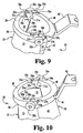
Fig. 9 is a perspective view of the upper portion of the unexpanded retractor ofFig 1 . -
Fig. 10 is a perspective view of the upper portion of the expanded retractor ofFig. 3 . -
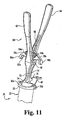
Fig. 11 is a perspective view of the upper portion of the unexpanded retractor ofFig. 1 with an expansion instrument positioned adjacent thereto. -
Fig. 12 is a perspective view of the retractor ofFig. 3 with the expansion instrument ofFig. 11 positioned therein to move the retractor to its expanded configuration. -
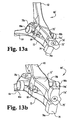
Figs. 13a-13dc illustrate another embodiment expansion instrument having an adjustable foot. -
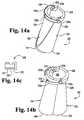
Figs. 14a-14c illustrate another embodiment expandable retractor and a coupling member comprising a portion thereof. -
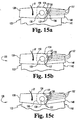
Figs. 15a-15c illustrate the proximal end of yet another embodiment expandable retractor. -
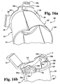
Figs. 16a-16b illustrate another embodiment expandable retractor. - For the purposes of promoting an understanding of the principles of the invention, reference will now be made to the embodiments illustrated in the drawings and specific language will be used to describe the same. It will nevertheless be understood that this is given by way of example only and that no limitation of the scope of the invention is thereby intended. The scope of the invention is defined by the claims.
- The present invention provides instruments for performing percutaneous surgery, including spinal surgeries that include one or more techniques such as laminotomy, laminectomy, foramenotomy, facetectomy, discectomy, interbody fusion, spinal nucleus or disc replacement, and implant insertion, for example. The surgery is performed through a working channel or passageway provided by a retractor. Viewing of the surgical site at the working end of the retractor can be accomplished with optics mounted on the retractor, positioned over the retractor, and/or through a viewing system such as lateral fluoroscopy. The retractor is expandable in situ to increase the size of the working channel to facilitate access to the working space at the distal end of the retractor while minimizing trauma to tissue surrounding the retractor. The retractor can be used with any surgical approach to the spine, including anterior, posterior, posterior mid-line, lateral, postero-lateral, and/or antero-lateral approaches, and in other regions besides the spine.
- In
Figs. 1-2 there is illustrated aretractor 20 that includes afirst portion 22 coupled to asecond portion 42.First portion 22 has adistal end 24 and an oppositeproximal end 26.Second portion 42 has adistal end 44 and an oppositeproximal end 46. In the illustrated embodiment,first portion 22 is pivotally coupled tosecond portion 42 atproximal ends channel 50 is formed byfirst portion 22 andsecond portion 42. Workingchannel 50 extends between and opens atdistal ends proximal ends Retractor 20 is movable to an expanded configuration, as shown inFigs. 3-4 , by pivotingfirst portion 22 andsecond portion 42 relative to one another aboutproximal ends second portion 42 to be moved away from one another to expandretractor 20 and increase the size of workingchannel 50 between its distal and proximal ends. -
Retractor 20 is insertable through skin and tissue of a patient to provide workingchannel 50 to the surgical site. It is contemplated thatretractor 20 is inserted through the skin and tissue in an unexpanded configuration, such as shown inFigs. 1-2 . After insertion into the patient,retractor 20 is expanded through the skin and tissue to an expanded configuration that increases the size of workingchannel 50 fromproximal ends distal ends -
First portion 22 includes asemi-cylindrical body 23 extending betweendistal end 24 andproximal end 26. Acollar 28 extends aboutproximal end 26, and forms alip 28a extending about the outer surface ofbody 23.Second portion 42 includes asemi-cylindrical body 43 extending betweendistal end 44 andproximal end 46. Acollar 48 extends aboutproximal end 46 ofsecond portion 42, and defines a lip 48a extending about the outer surface ofbody 43. Afirst coupling member 30a pivotally couples a first side offirst portion 22 tosecond portion 42 at theirproximal ends second coupling member 30b oppositefirst coupling member 30a pivotally couples the other side offirst portion 22 tosecond portion 42 at theirproximal ends retractor 20. - In the illustrated embodiment, first and
second coupling members collars first portion 22 tosecond portion 42. Other coupling arrangements are also contemplated at proximal ends 26, 46 of first andsecond portions proximal end 26 offirst portion 22 may be hingedly attached toproximal end 46 ofsecond portion 42 with one or more hinges at each side ofretractor 20. In another embodiment, at least the proximal ends offirst portion 22 andsecond portion 42 are formed of a single piece of material and a resilient hinge couplesfirst portion 22 tosecond portion 42 at their proximal ends 26, 46. Other embodiments contemplate a slotted arrangement extending around the proximal end of one of the retractor portions and one or more pins from the other retractor portion received in the slotted arrangement. - A
bracket 40 extends from and is integrally formed with or attached tocollar 48 ofsecond portion 42.Bracket 40 can also be provided oncollar 28 in lieu of or in addition tobracket 40 oncollar 48.Bracket 40 extends away from workingchannel 50 and is connectable to one end of a flexible or articulatable arm 41 (Fig. 6 .) The opposite end of arm 41 (not shown) can be mounted on the surgical table or other support device.Arm 41 supports retractor 20 in the patient yet allows percutaneous manipulation and repositioning ofretractor 20. -
Body 23 offirst portion 22 extends around at least a portion ofbody 43 ofsecond portion 42.Body 23 has a perimeter length alongdistal end 24 which is greater than the perimeter length ofbody 23 atproximal end 26.Body 43 ofsecond portion 42 includes a perimeter length alongdistal end 44 which is the same or can be about the same as the perimeter length ofbody 43 adjacentproximal end 46.Body 23 offirst portion 22 can be flexible enough to extend aroundsecond portion 42 in form fitting relationship whenretractor 20 is the unexpanded configuration ofFigs. 1 and 2 to minimize the profile ofretractor 20.Body 23 flexes outwardly and rides along the outer surface ofbody 43 ofsecond portion 42 asfirst portion 22 andsecond portion 42 are pivoted relative to one another to the expanded configuration ofretractor 20. - In one specific embodiment,
first portion 22 andsecond portion 42 are each made from surgical grade stainless steel. Other materials are also contemplated forbodies body 23 can be provided with a cross-sectional thickness t1 that provides the desired flexibility, yet is sufficiently rigid to maintain retraction of the skin and tissue.Body 43 ofsecond portion 42 can be provided with a thickness t2 that can be the same or greater than thickness t1 offirst portion 22. The reduced thickness ofbody 23 provides it greater flexibility to flex inwardly and outwardly expand aroundbody 43 ofsecond portion 42. Thickness t2 providessecond portion 43 with greater rigidity to resist bending or bowing under the forces exerted on it bybody 23 during and after movement ofretractor 20 to its expanded configuration. - In the unexpanded configuration, working
channel 50 has a generally circular cross-section alongretractor 20, as best shown inFig. 2 . Workingchannel 50 has a first width D1 between the opposite edges ofsecond portion 42 positioned infirst portion 22. A second width D2 is defined between the mid-portions offirst body 23 andsecond body 43 in the direction of expansion offirst portion 22 relative tosecond portion 42. In the illustrated embodiment, first and second widths D1 and D2 are substantially the same since unexpanded workingchannel 50 has a generally circular cross-section. In the expanded configuration, as shown inFig. 4 , the portion of the expanded workingchannel 50 extending along the opposite edges ofsecond body 43 maintains first width D1. However,first body 23 is flexed outwardly relative tosecond body 43, and defines a third width D3 between the sides offirst body 23 that is greater than first width D1. In the expanded configuration of workingchannel 50,first body 23 and second body'43 define a fourth width D4 in the direction of expansion offirst portion 22 relative tosecond portion 42 that is greater than second width D2. It is further contemplated that width D4 can be greater than widths D1 and D3. - Various configurations for working
channel 50 are contemplated. In the unexpanded configuration, workingchannel 50 can have a cylindrical shape with, for example, a circular, oval, elliptical, or polygonal cross-section. In the expanded configuration, workingchannel 50 can have a frusto-conical shape with, for example a cross-section that is figure-eight or snowman shaped, oval, elliptical, circular or polygonal. In at least the direction of expansion, the size of the cross-section of workingchannel 50 decreases from distal end to the proximal end ofretractor 20. - In one specific application for spinal surgery, it is contemplated that, after insertion of
retractor 20,first portion 22 andsecond portion 42 are expanded predominantly in one direction to retract muscle and tissue along pathway P. For example,retractor 20 can be primarily or predominantly expandable in the direction of the spinal column axis. Since the muscle tissue adjacent the spine has a fiber orientation that extends generally in the direction of the spinal column axis, the expansion ofretractor 20 separates the muscle tissue along the fibers, thus minimizing their separation and the resultant tearing and trauma to the muscle tissue is minimized. It is also contemplated in othertechniques employing retractor 20 that workingchannel 50 expands primarily in a direction other than along the spinal column axis or in areas other than spine. Embodiments ofretractor 20 are also contemplated in which workingchannel 50 is circular or polygonal in cross-suction and expands substantially the same amount in all directions. - Referring now to
Figs. 5-6 , positioning ofretractor 20 through the skin S and tissue T of the patient will be described. An incision is made in skin S adjacent the location of a patient's anatomy to be accessed. For example, in spinal surgery, the incision can be made at a vertebral level at a location that provides access to the disc space between adjacent vertebrae or to one or more vertebra through a desired approach. Prior to insertion ofretractor 20, skin S and tissue T can be sequentially dilated via guidewires and/or one or more dilators of increasing size to form a pathway P through skin S and tissue T to the surgical site in the patient. In such procedures,retractor 20 is positioned over the last inserted dilator in pathway P forretractor 20. Workingchannel 50 throughretractor 20 provides access to a working space WS at the distal end ofretractor 20 when the guidewires and dilators, if used, are removed therefrom. - For the entire surgery or for certain procedures, it may be desired by the surgeon to increase the size of working
channel 50 to facilitate access working space WS below the distal end ofretractor 20, or to even provide a greater working space WS.Retractor 20 can be pivoted from its unexpanded, insertion configuration to an expanded configuration as shown inFig. 6 . In the expanded configuration,first portion 22 andsecond portion 42 are pivoted away from one another about first andsecond coupling members first portion 22 andsecond portion 42. The size of working space WS can be increased while minimizing trauma to the tissue and skin along pathway P. - Working
channel 50 has a tapered configuration that reduces in size from the distal end ofretractor 20 adjacent working space WS through skin S to the proximal end ofretractor 20. The tapered working channel provides the surgeon greater access and increased visualization of working space WS. The tapered workingchannel 50 also allows greater angulation of instruments placed through workingchannel 50, more selection in positioning of instruments within workingchannel 50, and the ability to position instruments adjacent the inner wall surfaces of the expanded first andsecond portions - Viewing instruments can be positioned in or adjacent to working
channel 50 to facilitate surgeon viewing of working space WS and the operative site. For example, anendoscopic viewing element 90 can be mounted on the proximal end ofretractor 20 such that its scope portion 92 extends along workingchannel 50. Amicroscopic viewing element 95 can also be positioned over the proximal end ofretractor 20 for viewing working space WS and the surgical site. Other imaging techniques, such as lateral fluoroscopy, can be used alone or in combination with the endoscopic and microscopic viewing elements. - It is further contemplated that other instruments can be mounted on the proximal end of
retractor 20, such as nerve root retractors, tissue retractors, irrigation and/or aspiration instruments, illumination instruments and the like for use in surgical procedures throughretractor 20 in the working space. - Referring now to
Fig. 7 , further details regarding the engagement offirst portion 22 andsecond portion 42 whenretractor 20 is in the expanded configuration will be provided.First body 23 offirst portion 22 includes a first edge 32a extending betweendistal end 24 andproximal end 26.First body 23 offirst portion 22 includes an oppositesecond edge 32b extending betweendistal end 24 andproximal end 26.Second portion 42 includes afirst edge 51 a extending along one side ofsecond body 43 and an oppositesecond edge 51b extending along the opposite side ofsecond body 43.First edge 51a includes agrooved portion 54a extending fromdistal end 44 along at least a portion of the length offirst edge 51a. An engagement surface 52a extends along groovedportion 54a. Similarly,second edge 51b includes groovedportion 54b extending fromdistal end 44 along at least a portion of the length ofsecond edge 51b. Anengagement surface 52b extends along groovedportion 54b. - With
retractor 20 in its expanded configuration,first edge 51a ofsecond body 43 is adjacent first edge 32a offirst body 23, andsecond edge 51b ofbody 43 is adjacentsecond edge 32b offirst body 23. First edge 32a resides at least partially ingrooved portion 54a, andsecond edge 32b resides at least partially ingrooved portion 52b. First edge 32a contacts engagement surface 52a alonggrooved portion 54a to maintainretractor 20 in its expanded configuration. Similarly,second edge 32bcontacts engagement surface 52b ingrooved portion 54b to maintainretractor 20 in its expanded configuration. The flexiblefirst portion 22 tends to return toward its unexpanded configuration, thus first andsecond edges 32a, 32b frictionally engage the engagement surfaces extending along each of thegrooved portions first portion 22 with respect tosecond portion 42 in the expanded configuration, resisting collapse of the working channel by pressure of the surrounding tissue on first andsecond portions retractor 20 in the tissue without collapse of the working channel. - Other means for locking first and
second portion second portion 42 can be provided with a ridge or protrusion at each of its opposite edges, andfirst portion 44 can engage the ridge or protrusion. - By maintaining a closed configuration for the working channel between
first portion 22 andsecond portion 42 in the expanded configuration, migration of tissue into workingchannel 50 is prevented by the walls of first andsecond portions channel 50 is not completely enclosed. - Referring now to
Figs. 8-10 , further details regarding proximal ends 26, 46 of first andsecond portions Collar 28 includes arecess 33a formed adjacent first edge 32a on one side offirst portion 22, and asecond recess 33b oppositefirst recess 33a on the other side offirst portion 22.Recess 33a includes anengagement surface 35a along an inner side thereof, andsecond recess 33b includes anengagement surface 35b extending along an inner side thereof. Afirst extension 34a extends along the outside offirst recess 33a, and asecond recess 34b extends along the outside ofsecond recess 33b.First extension 34a andsecond extension 34b extend beyond the adjacent first edge 32a andsecond edge 32b, respectively, ofbody 23 offirst portion 22. -
Second portion 42 includes afirst recess 55a along one side ofsecond portion 42, and asecond recess 55b along another side ofsecond portion 42.First recess 55a includes anengagement surface 56a, andsecond recess 55b includes anengagement surface 56b. Afirst extension 58a extends along the inner side offirst recess 55a, and asecond extension 58b extends along the inner side ofsecond recess 55b.First extension 58a includes anengagement surface 59a, andsecond extension 55b also includes a similarly situated engagement surface.First extension 58a resides withinfirst recess 33a adjacentfirst extension 34a offirst portion 22, andsecond extension 58b resides withinsecond recess 33b adjacentsecond extension 34b offirst portion 22.First coupling member 30a includes a pin extending throughpassage 31 a offirst extension 34a offirst portion 22 and pivotally couplesfirst extension 58a ofsecond portion 42 thereto.Second coupling member 30b includes a pin extending throughpassage 31b ofsecond extension 34b offirst portion 22 and pivotally couplessecond extension 58b ofsecond portion 42 thereto. - With
retractor 20 in its unexpanded configuration as shown inFig. 9 , a gap is formed betweenengagement surfaces first portion 22 andengagement surfaces extensions second portion 42. Asretractor 20 is moved to its expanded configuration as shown inFig. 10 ,engagement surfaces contact engagement surfaces first portion 22. Also,engagement surfaces 37a, 37b ofextensions first portion 22contact engagement surfaces second portion 42. The contact between the engagement surfaces of the recesses and extensions limit the pivotal movement offirst portion 22 relative tosecond portion 42.First portion 22 can include arelieved portion 39a belowfirst engagement surface 59a and a similar relief undersecond engagement surface 35b. The reliefs allow some flexing ofengagement surfaces engagement surfaces 59a, 59b ofextensions engagement surfaces - Referring now to
Figs. 11-12 there is shownretractor 20 with anexpansion instrument 60.Expansion instrument 60 includes afirst handle 62 pivotally coupled to asecond handle 64 withpin 66. Aleaf spring 68 can extend betweenfirst handle 62 andsecond handle 64 to bias handles 62, 64 in a closed position as shown inFig. 11 . Extending distally from the pivotal connection offirst handle 62 andsecond handle 64 are firstdistal portion 70 and seconddistal portion 72, respectively.Distal portion 70 includes afoot 74 at a distal end thereof, anddistal portion 72 includes afoot 76 at a distal-end thereof.Feet first portion 22 andsecond portion 42, respectively whenexpansion instrument 60 is inserted in workingchannel 50 ofretractor 20. -
Expansion instrument 60 includes afirst arm 78a and asecond arm 78b abovepin 66.First arm 78a is pivotally coupled to first andsecond handles coupler 84a, andsecond arm 78b is pivotally coupled to first andsecond handles coupler 84b. First andsecond arms feet First arm 78a includes anengagement member 80a having areceptacle 82a positionable over the head offirst coupling member 30a.Second arm 78b includes anengagement member 80b having a receptacle positionable over the head ofsecond coupling member 30b. - As shown in
Fig. 12 ,expansion instrument 60 is mountable onretractor 20 by pivotingfirst arm 78a so thatfirst coupling member 30a is captured inreceptacle 82a ofengagement member 80a, andsecond coupling member 30b is captured in receptacle 82b ofengagement member 80b. The engagement ofexpansion instrument 60 toretractor 20 ensures thatexpansion instrument 60 is not inserted too far into workingchannel 50 before and during insertion, and allows the application a steady and uniform expansion force withoutexpansion instrument 60 slipping relative toretractor 20. Withexpansion instrument 60 mounted onretractor 20, handles 62, 64 are pressed toward one another in order to movefeet first portion 22,second portion 42 and into contact with adjacentfirst portion 22 andsecond portion 42.Feet first portion 22 andsecond portion 42 to pivot first andsecond portions retractor 20 to its expanded configuration.Retractor 20 can be locked in the expanded configuration by engagement ofedges 32a, 32b offirst portion 22 with the respective engagement surfaces ofsecond portion 42. - To collapse
retractor 20 to its unexpanded configuration,expansion instrument 60 is rotated 90 degrees so thefeet first portion 22 in the direction of the pivot axis offirst portion 22 andsecond portion 42. The expansion offirst portion 22 in this direction disengages or unlocksedges 32a, 32b fromengagement surfaces 52a, 52b ofsecond portion 42 and allowsfirst portion 22 andsecond portion 42 to pivot relative to one another tounexpand retractor 20.Retractor 20 can then be withdrawn from the tissue in its unexpanded condition, minimizing pressure on the adjacent tissue asretractor 20 is withdrawn. - Referring now to
Figs. 13a-13d , there is shown anotherembodiment expansion instrument 60'. Except as otherwise provided,expansion instrument 60' can be similar toexpansion instrument 60 discussed above, and like elements betweenexpansion instruments Expansion instrument 60' includes a movable foot 74' coupled to distal portion 70'. In the illustrated embodiment, foot 74' is rotatable about pin 75' relative to distal portion 70' in order to position selected ones of the retractor portion contact surfaces 74a', 74b' or 74c' adjacent one of theretractor portions - The contact surfaces 74a', 74b' and 74c' are located at differing distances from pin 75' to allow the surgeon to select the desired amount of expansion for
retractor 20. Foot 74' is rotated about pin 75' to select the desired contact surface by orienting the desired contact surface away fromcontact surface 76a offoot 76. For example, as shown inFig. 13a , contact surface 74a' is selected to provide minimum expansion since it is located closest to pin 75'. InFig. 13b contact surface 74b' is selected to provide maximum expansion since it is located furthest away from pin 75'. InFig. 13c contact surface 74c' is selected to provide intermediate expansion since it has a distance from pin 75' that is between the distances of contact surface 74a' and contact surface 74b'.Fig. 13d showsexpansion instrument 60' mounted onretractor 20 withcontact surface 74c' offoot 74 in contact withsecond portion 42 andcontact surface 76a offoot 76 in contact withfirst portion 22 ofretractor 20. - It is further contemplated that the amount of expansion provided by each of the contact surfaces 74a', 74b' and 74c' can correspond to a particular retractor length. For example, with
expansion instrument 60' mounted on the retractor, the depth whichexpansion instrument 60' extends into the retractor is the same no matter the length of the retractor. Thus, to provide the same size opening at the distal end of the retractor, the first and second portions of a shorter retractor will be separated a greater amount at the depth offeet 74', 76 than will a longer retractor. Accordingly, contact surface 74a' can be selected for a longer length retractor, contact surface 74b' can be selected for a shorter length retractor, andcontact surface 74c' can be selected for an intermediate length retractor. - Of course,
expansion instruments feet 74, 74' contactfirst portion 22 andfoot 76 contactssecond portion 42. It is further contemplated thatexpansion instruments - It is contemplated that for spinal surgery
various retractors 20 can be provided in a kit with lengths ranging from 20 millimeters to 100 millimeters in increments of 10 or 20 millimeters. It is further contemplated thatretractor 20 can be provided in a kit with various diameters, such as 14, 16, 18, 20, 21 or 25 millimeters in its unexpanded configuration. It should be understood, however, that the present invention contemplates thatretractor 20 can have other lengths and diameters and can be provided in a kit with different increments. The appropriate length forretractor 20 will depend on the depth of the desired surgical location below the skin S of the patient, the anatomical location of the surgery, and the patient's anatomy. These factors in retractor selection can be evaluated through pre-operative planning prior to surgery by x-rays or other known imaging technique, and can be adjusted during the surgical procedure if necessary since retractors of differing lengths and diameters can be made available. - In
Figs. 14a-14b , there is shown another embodimentexpandable retractor 220. InFig. 14a ,retractor 220 is in its unexpanded configuration and inFig. 14b retractor 220 is in its expanded configuration.Retractor 220 is similar in many respects to retractor 20 discussed above.Retractor 220 includes afirst portion 222 having adistal end 224, aproximal end 226, and acollar 228 atproximal end 226.Retractor 220 further includes asecond portion 242 having adistal end 244, aproximal end 246, and acollar 248 atproximal end 246.First coupling member 230a andsecond coupling member 230b pivotally couplefirst portion 222 tosecond portion 242. Afirst lever arm 232a is connected with and extends fromfirst coupling member 230a aroundcollar 248, and asecond lever arm 232b is connected with and extends fromsecond coupling member 230b aroundcollar 248. - In the unexpanded configuration,
lever arms adjacent collar 248, andcoupling members collar 228 as shown inFig. 14a . Couplingmembers Fig. 13c , have a first keyedportion 237 configured to engage slottedhole 234 ofcollar 248. Thecylindrical portions 239 ofcoupling members collar 228 offirst portion 222. This allowsfirst portion 222 to be pivoted relative tosecond portion 242 aboutcoupling members - When
first portion 222 is pivoted relative tosecond portion 242 to the expanded configuration, the slotted portions of slottedhole 234 and the slotted hole throughcollar 228 are aligned. Couplingmembers portion 235 ofcoupling members collar 228, while the first keyedportion 237 remains engaged in slottedhole 234 ofcollar 248, thus fixingfirst portion 222 relative tosecond portion 242.Lever arms collar 248 whenfirst portion 222 is locked relative tosecond portion 242. To move retractor 220 to the unexpanded configuration,lever arms collar 248 to movecoupling members portions 235 out of engagement with the slotted holes incollar 228 offirst portion 222.First portion 222 can then pivot towardsecond portion 242 to collapseretractor 220 for withdrawal from the patient. - In this embodiment, rather than providing an engagement surface along the opposite edges of
second portion 242, the keyed engagement ofcoupling members second portions - Other means for maintaining first and second portions of the retractor in an expanded configuration are also contemplated. For example, in
Figs. 15a-15c another embodimentexpandable retractor 120 is shown with a ratchet and pawl type mechanism at the proximal ends offirst portion 122 andsecond portion 142. In this embodiment, rather than providing a grooved portion and engagement surface along the opposite edges ofsecond portion 142, the ratchet and pawl mechanism maintainsretractor 120 in its expanded configuration. However, the provision of a grooved portion and engagement surface is not precluded. -
First portion 122 includes acollar 128 at its proximal end.Collar 128 includes anextension 134 extending from each side thereof, it being understood that only one side is shown inFigs. 15a-15c . Similarly,second portion 142 includes anextension 158 extending from each side thereof that is positionable alongsideextension 134 offirst portion 122, it being understood that only one side is shown inFigs. 15a-15c . Apin 130pivotally couples extensions Extension 134 includes a number ofteeth 137 formed at the end thereof that are engageable withends 156 ofpawls 157 extending aroundcollar 148.Pawls 157 are biased into engagement withteeth 137 and moveable relative tocollar 148 for disengagement ofends 156 withteeth 137. - When in the unexpanded configuration (not shown)
teeth 156 are not engaged by any of thepawls 157. InFig. 15a ,retractor 120 is expanded by pivotingfirst portion 122 in the direction of arrow R relative tosecond portion 142 so thatlower pawl 157 is biased into engagement withlower tooth 137. InFig. 15b ,first portion 122 is further pivoted in the direction of arrow R relative tosecond portion 142 to expandretractor 120 with theend 156 ofmiddle pawl 157 in engagement with themiddle tooth 137. InFig. 15c first portion 122 is further pivoted in the direction of arrow R relative tosecond portion 142 to expandretractor 120 with theend 156 ofupper pawl 157 in engagement with theupper tooth 137. It is contemplated thatteeth 137 andpawls 157 can be spaced so thatretractor 120 is expanded incrementally. In one specific embodiment, the teeth 136 andpawls 157 are spaced so thatfirst portion 122 is pivoted in 5 degree increments relative tosecond portion 142, ranging from 0 degrees to 15 degrees. Other increments are also contemplated. -
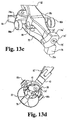
Figs. 16a-16b illustrate anotherembodiment retractor 320 that is similar toretractor 20 but includes another proximal end configuration. InFig. 16b ,retractor 320 is in its unexpanded configuration and inFig. 16a retractor 320 is in its expanded configuration.Retractor 320 includes afirst portion 322 having adistal end 324, aproximal end 326, and acollar 328 atproximal end 326.Retractor 320 further includes asecond portion 342 having adistal end 344, aproximal end 346, and acollar 348 atproximal end 346.First coupling member 330a andsecond coupling member 330b pivotally couplefirst portion 322 tosecond portion 342 about a pivotaxis A. Collars collars retractor 20, reducing the retractor length. Viewing instruments and other instruments can be positioned in, over, and/or attached toretractor 320 as discussed above with respect toretractor 20. -
Collar 328 includes afirst extension 334a extending along one side thereof and abovecollar 328, and asecond extensions 334b extending along the other side thereof and abovecollar 328.First extension 334a andsecond extension 334b are offset laterally with respect tocollar 328 to form recesses for receiving respective ones of theextensions collar 348 therealong so thatextensions retractor 320.Extensions collar 348. Aligned holes are provided throughadjacent extensions adjacent extensions coupling members collars first portion 322 andsecond portion 342 are expandable through their respective proximal ends tocoupling members -
Collar 328 includes a first contact surface 335a belowfirst extension 358a ofcollar 348, and a second contact surface 335b belowsecond extension 358b ofcollar 348.Collar 348 includes a firstlateral extension 356a that provides a contact surface belowfirst extension 334a ofcollar 328, and an opposite second lateral extension that provides a contact surface belowsecond extension 334b ofcollar 328. Withretractor 320 in its unexpanded configuration as shown inFig. 16b , a gap is formed between the adjacent extensions and engagement surfaces ofcollars retractor 320 is expanded sufficiently,extensions collar 348, andextensions collar 328, preventing over-expansion ofretractor 320. - While the invention has been illustrated and described in detail in the drawings and foregoing description, the same is to be considered as illustrative and not restrictive in character, it being understood that only the preferred embodiment has been shown and described and that all changes and modifications that come with the scope of the invention as defined by the claims are desired to be protected. For example, certain embodiments-contemplate that the first and second portions of the retractor are not provided with proximal end collars. Other embodiments contemplate the first and second portions are not pivotally coupled to one another, but rather to intermediate members extending between the first and second portions along each side of the retractor.
Claims (23)
- A retractor for percutaneous surgery in a patient, comprising:a first portion (22) having a proximal end (26) and a distal end (24);a second portion (42) having a proximal end (46) coupled to said proximal end of said first portion, said second portion having a distal end (44) and forming with said first portion a working channel (50), said working channel having a length between said distal ends and said proximal ends of said first and second portions and a size between said first portion and said second portion along said length, wherein:said first and second portions are positionable in an unexpanded configuration with said distal ends of said first and second portions in the patient and said proximal ends of said first and second portions outside the patient; and said first and second portions are moveable to an expanded configuration wherein said working channel tapers in size from said distal ends in the patient to said proximal ends outside the patient and said second portion includes a part-cylindrical body (43) and said first portion includes a flexible part-cylindrical body (23) positioned about said part-cylindrical body of said second portion.
- The retractor of claim 1, further comprising an endoscopic viewing instrument (90) extending through said working channel.
- The retractor of claim 1, further comprising a microscopic viewing instrument (95) over said working channel.
- The retractor of claim 1, wherein said body of said first portion has a perimeter length between opposite edges of said second portion (42), said perimeter length being greater at said distal end of said first portion than at said proximal end of said first portion.
- The retractor of claim 1, wherein said body of said second portion further includes an engagement surface extending along at least a portion of each of opposite edges thereof.
- The retractor of claim 5, wherein opposite edges of said first portion engage adjacent ones of said engagement surfaces of said second portion when in said expanded configuration.
- The retractor of claim 1, wherein said first portion includes a collar (28) at said proximal end thereof and said second portion includes a collar (48) at said proximal end thereof.
- The retractor of claim 7, wherein said first portion and said second portion are pivotally coupled to one another at said collars.
- The retractor of claim 8, wherein:said collar of said first portion includes first and second extension (34a, 34b) extending therefrom on opposite sides of said first portion; andsaid collar of said second portion includes first and second recesses (55a, 55b) therein on opposite sides of said second portion, said first and second extensions positionable in respective ones of said first and second recesses.
- The retractor of claim 9, wherein said collar of said second portion includes first and second extensions (58a, 58b) extending along said first and second recesses of said second collar, said first and second extensions of said first portion are each pivotally coupled to an adjacent one of said first and second extensions of said second portion in respective ones of said first and second recesses of said second portion.
- The retractor of claim 10, wherein said collar of said first portion includes first and second recesses (33a, 33b) therein adjacent respective ones of said first and second extensions of said first portion, said first and second extension of said second portion are positionable in respective ones of said first and second recesses of said first portion.
- The retractor of claim 11, wherein:said first and second extensions of said first portion each contact an engagement surface (56a, 56b) in each of said first and second recesses of said second portion in said expanded configuration; andsaid first and second extensions of said second portion each contact an engagement surface (35a, 35b) in each of said first and second recesses of said first portion in said expanded configuration.
- The retractor of claim 1, wherein said working channel has a figure eight shape along said length in said expanded configuration.
- The retractor of claim 13, wherein in said unexpanded configuration said working channel has a generally circular cross-section along said length and in said expanded configuration said working channel has a dimension in said second portion transverse to a primary expansion direction of said first and second portions that is less than a dimension of said working channel in said first portion transverse to said primary expansion direction.
- The retractor of claim 1, wherein one of said first and second portions includes a bracket (40) extending from said proximal end thereof that is engageable to a flexible arm (41).
- The retractor of claim 1, wherein said first portion and said second portion extend completely about said working channel from said proximal ends of said first and second portions to said distal ends of said first and second portions.
- The retractor of claim 1, further comprising a ratchet and pawl mechanism at said proximal ends of said first and second portions to maintain said first and second portions in an expanded configuration.
- The retractor of claim 1, further comprising:a pair of coupling members (30a, 30b) engaging said first portion to said second portion;a lever arm extending from respective ones of each of said pair of coupling members; andsaid coupling members each have a first position wherein said first portion is pivotal relative to said second portion and are moveable to a second position wherein said coupling members fix said first portion relative to said second portion, said lever arms being moveable to move said coupling members from said second position to said first position.
- The retractor of claim 1, wherein said first portion is pivotally coupled to said second portion about a pivot axis located proximally of said proximal ends of said first and second portions.
- A kit for use in percutaneous surgery, comprising:a retractor as claimed in any preceding claim; andan expansion instrument (60) positionable in said working channel and engageable with said first portion and said second portion to move said first and second portions to said expanded configuration, said expansion instrument mountable on said proximal end of said retractor.
- The kit of claim 20, wherein said expansion instrument includes a pair of arms pivotally extending therefrom, said arms each including a mounting member engageable with a corresponding one of first and second coupling members on said retractor to mount said expansion instrument on said proximal end of said retractor.
- The kit of claim 20, wherein said expansion instrument includes a pair of proximal handles (62, 64) pivotally coupled to one another and a pair of distal feet (74, 76) extending from a respective one of said pair of handles, each of said distal feet engageable with a respective one of said first and second portions.
- The kit of claim 22, wherein at least one of said distal feet is adjustable to select a desired amount of expansion.
Priority Applications (2)
| Application Number | Priority Date | Filing Date | Title |
|---|---|---|---|
| EP10180674.3A EP2258276A3 (en) | 2002-04-05 | 2003-04-02 | Devices for percutaneous tissue retraction |
| EP08164466.8A EP1994889B1 (en) | 2002-04-05 | 2003-04-02 | Devices for percutaneous tissue retraction |
Applications Claiming Priority (3)
| Application Number | Priority Date | Filing Date | Title |
|---|---|---|---|
| US117440 | 2002-04-05 | ||
| US10/117,440 US7261688B2 (en) | 2002-04-05 | 2002-04-05 | Devices and methods for percutaneous tissue retraction and surgery |
| PCT/US2003/010090 WO2003086202A2 (en) | 2002-04-05 | 2003-04-02 | Devices and methods for tissue retraction |
Related Child Applications (2)
| Application Number | Title | Priority Date | Filing Date |
|---|---|---|---|
| EP08164466.8A Division EP1994889B1 (en) | 2002-04-05 | 2003-04-02 | Devices for percutaneous tissue retraction |
| EP10180674.3A Division EP2258276A3 (en) | 2002-04-05 | 2003-04-02 | Devices for percutaneous tissue retraction |
Publications (2)
| Publication Number | Publication Date |
|---|---|
| EP1494592A2 EP1494592A2 (en) | 2005-01-12 |
| EP1494592B1 true EP1494592B1 (en) | 2008-09-17 |
Family
ID=28674201
Family Applications (3)
| Application Number | Title | Priority Date | Filing Date |
|---|---|---|---|
| EP03746580A Expired - Lifetime EP1494592B1 (en) | 2002-04-05 | 2003-04-02 | Devices and methods for tissue retraction |
| EP08164466.8A Expired - Lifetime EP1994889B1 (en) | 2002-04-05 | 2003-04-02 | Devices for percutaneous tissue retraction |
| EP10180674.3A Withdrawn EP2258276A3 (en) | 2002-04-05 | 2003-04-02 | Devices for percutaneous tissue retraction |
Family Applications After (2)
| Application Number | Title | Priority Date | Filing Date |
|---|---|---|---|
| EP08164466.8A Expired - Lifetime EP1994889B1 (en) | 2002-04-05 | 2003-04-02 | Devices for percutaneous tissue retraction |
| EP10180674.3A Withdrawn EP2258276A3 (en) | 2002-04-05 | 2003-04-02 | Devices for percutaneous tissue retraction |
Country Status (10)
| Country | Link |
|---|---|
| US (6) | US7261688B2 (en) |
| EP (3) | EP1494592B1 (en) |
| JP (1) | JP4336204B2 (en) |
| KR (1) | KR101190948B1 (en) |
| CN (1) | CN100396245C (en) |
| AT (1) | ATE408376T1 (en) |
| AU (1) | AU2003262144B2 (en) |
| CA (1) | CA2481180A1 (en) |
| DE (1) | DE60323617D1 (en) |
| WO (1) | WO2003086202A2 (en) |
Families Citing this family (247)
| Publication number | Priority date | Publication date | Assignee | Title |
|---|---|---|---|---|
| US7682370B2 (en) * | 1998-08-20 | 2010-03-23 | Zimmer Spine, Inc. | Surgical tool for use in expanding a cannula |
| US7799036B2 (en) * | 1998-08-20 | 2010-09-21 | Zimmer Spine, Inc. | Method and apparatus for securing vertebrae |
| US6187000B1 (en) | 1998-08-20 | 2001-02-13 | Endius Incorporated | Cannula for receiving surgical instruments |
| JP2003524452A (en) | 1998-12-23 | 2003-08-19 | ヌバシブ, インコーポレイテッド | Nerve monitoring cannula system |
| KR20020077346A (en) | 1999-11-24 | 2002-10-11 | 너바시브 인코퍼레이티드 | Electromyography system |
| US7985247B2 (en) | 2000-08-01 | 2011-07-26 | Zimmer Spine, Inc. | Methods and apparatuses for treating the spine through an access device |
| US7056321B2 (en) | 2000-08-01 | 2006-06-06 | Endius, Incorporated | Method of securing vertebrae |
| EP1418851B1 (en) | 2001-03-01 | 2012-05-09 | Warsaw Orthopedic, Inc. | Dynamic lordotic guard with movable extensions for creating an implantation space posteriorly in the lumbar spine and method for use thereof |
| US6896680B2 (en) | 2001-03-01 | 2005-05-24 | Gary K. Michelson | Arcuate dynamic lordotic guard with movable extensions for creating an implantation space posteriorly in the lumbar spine |
| US7144393B2 (en) * | 2001-05-15 | 2006-12-05 | Dipoto Gene P | Structure for receiving surgical instruments |
| EP1417000B1 (en) | 2001-07-11 | 2018-07-11 | Nuvasive, Inc. | System for determining nerve proximity during surgery |
| JP2005503857A (en) | 2001-09-25 | 2005-02-10 | ヌバシブ, インコーポレイテッド | Systems and methods for performing surgical procedures and surgical diagnosis |
| JP3913506B2 (en) * | 2001-09-26 | 2007-05-09 | 三洋電機株式会社 | Disc recording or playback device with a tray that can be moved up and down |
| WO2003057051A1 (en) * | 2002-01-09 | 2003-07-17 | Synthes Ag Chur | Device for drilling or for inserting implants |
| US7261688B2 (en) * | 2002-04-05 | 2007-08-28 | Warsaw Orthopedic, Inc. | Devices and methods for percutaneous tissue retraction and surgery |
| EP1534201B1 (en) | 2002-06-05 | 2011-05-25 | Applied Medical Resources Corporation | Wound retractor |
| US7004947B2 (en) | 2002-06-24 | 2006-02-28 | Endius Incorporated | Surgical instrument for moving vertebrae |
| US7473222B2 (en) * | 2002-06-26 | 2009-01-06 | Warsaw Orthopedic, Inc. | Instruments and methods for minimally invasive tissue retraction and surgery |
| US7582058B1 (en) | 2002-06-26 | 2009-09-01 | Nuvasive, Inc. | Surgical access system and related methods |
| US6945933B2 (en) * | 2002-06-26 | 2005-09-20 | Sdgi Holdings, Inc. | Instruments and methods for minimally invasive tissue retraction and surgery |
| US9259144B2 (en) * | 2002-07-11 | 2016-02-16 | Nuvasive, Inc. | Surgical access system and related methods |
| US7306603B2 (en) | 2002-08-21 | 2007-12-11 | Innovative Spinal Technologies | Device and method for percutaneous placement of lumbar pedicle screws and connecting rods |
| US6648888B1 (en) * | 2002-09-06 | 2003-11-18 | Endius Incorporated | Surgical instrument for moving a vertebra |
| US8137284B2 (en) | 2002-10-08 | 2012-03-20 | Nuvasive, Inc. | Surgical access system and related methods |
| US7946982B2 (en) | 2002-10-25 | 2011-05-24 | K2M, Inc. | Minimal incision maximal access MIS spine instrumentation and method |
| US7887482B2 (en) * | 2002-10-25 | 2011-02-15 | K2M, Inc. | Minimal access lumbar diskectomy instrumentation and method |
| US6849064B2 (en) * | 2002-10-25 | 2005-02-01 | James S. Hamada | Minimal access lumbar diskectomy instrumentation and method |
| WO2004039235A2 (en) * | 2002-10-25 | 2004-05-13 | Endius Incorporated | Apparatus and methods for shielding body structures during surgery |
| US7850608B2 (en) | 2002-10-25 | 2010-12-14 | K2M, Inc. | Minimal incision maximal access MIS spine instrumentation and method |
| US7935054B2 (en) * | 2002-10-25 | 2011-05-03 | K2M, Inc. | Minimal access lumbar diskectomy instrumentation and method |
| US20060155170A1 (en) * | 2002-12-13 | 2006-07-13 | Synthes Spine Company, Lp | Guided retractor and methods of use |
| US7014608B2 (en) * | 2002-12-13 | 2006-03-21 | Synthes Spine Company, Lp | Guided retractor and methods of use |
| US20040116777A1 (en) * | 2002-12-13 | 2004-06-17 | Jeffrey Larson | Guided retractor and methods of use |
| US7691057B2 (en) | 2003-01-16 | 2010-04-06 | Nuvasive, Inc. | Surgical access system and related methods |
| US7819801B2 (en) | 2003-02-27 | 2010-10-26 | Nuvasive, Inc. | Surgical access system and related methods |
| US7645232B2 (en) | 2003-05-16 | 2010-01-12 | Zimmer Spine, Inc. | Access device for minimally invasive surgery |
| US7481766B2 (en) | 2003-08-14 | 2009-01-27 | Synthes (U.S.A.) | Multiple-blade retractor |
| DE602004018342D1 (en) * | 2003-08-26 | 2009-01-22 | Zimmer Spine Inc | ACCESS SYSTEMS FOR MINIMALLY INVASIVE SURGERY |
| US7226451B2 (en) * | 2003-08-26 | 2007-06-05 | Shluzas Alan E | Minimally invasive access device and method |
| JP4504376B2 (en) * | 2003-09-18 | 2010-07-14 | ハウメディカ・オステオニクス・コーポレイション | Surgical retractor with removable arm |
| US20050203513A1 (en) * | 2003-09-24 | 2005-09-15 | Tae-Ahn Jahng | Spinal stabilization device |
| US7763052B2 (en) | 2003-12-05 | 2010-07-27 | N Spine, Inc. | Method and apparatus for flexible fixation of a spine |
| US7815665B2 (en) | 2003-09-24 | 2010-10-19 | N Spine, Inc. | Adjustable spinal stabilization system |
| US20050065516A1 (en) | 2003-09-24 | 2005-03-24 | Tae-Ahn Jahng | Method and apparatus for flexible fixation of a spine |
| US8979900B2 (en) | 2003-09-24 | 2015-03-17 | DePuy Synthes Products, LLC | Spinal stabilization device |
| US7905840B2 (en) | 2003-10-17 | 2011-03-15 | Nuvasive, Inc. | Surgical access system and related methods |
| JP4463819B2 (en) | 2003-09-25 | 2010-05-19 | ヌヴァシヴ インコーポレイテッド | Surgical access system |
| US7655012B2 (en) | 2003-10-02 | 2010-02-02 | Zimmer Spine, Inc. | Methods and apparatuses for minimally invasive replacement of intervertebral discs |
| US20050090822A1 (en) * | 2003-10-24 | 2005-04-28 | Dipoto Gene | Methods and apparatus for stabilizing the spine through an access device |
| US20050090899A1 (en) * | 2003-10-24 | 2005-04-28 | Dipoto Gene | Methods and apparatuses for treating the spine through an access device |
| US7731737B2 (en) * | 2003-10-24 | 2010-06-08 | Zimmer Spine, Inc. | Methods and apparatuses for fixation of the spine through an access device |
| US8313430B1 (en) | 2006-01-11 | 2012-11-20 | Nuvasive, Inc. | Surgical access system and related methods |
| US7125211B2 (en) * | 2003-10-17 | 2006-10-24 | Racer Machinery International Inc. | Apparatus and method for damping vibration in a machine tool |
| US7144368B2 (en) * | 2003-11-26 | 2006-12-05 | Synthes Spine Company, Lp | Guided retractor and methods of use |
| US7527638B2 (en) * | 2003-12-16 | 2009-05-05 | Depuy Spine, Inc. | Methods and devices for minimally invasive spinal fixation element placement |
| US7666188B2 (en) | 2003-12-16 | 2010-02-23 | Depuy Spine, Inc. | Methods and devices for spinal fixation element placement |
| WO2005060837A2 (en) * | 2003-12-18 | 2005-07-07 | Depuy Spine, Inc. | Surgical retractor systems, illuminated cannulae, and methods of use |
| US7547318B2 (en) | 2004-03-19 | 2009-06-16 | Depuy Spine, Inc. | Spinal fixation element and methods |
| US7435219B2 (en) * | 2004-03-25 | 2008-10-14 | Depuy Spine, Inc. | Surgical retractor positioning device |
| US20050251192A1 (en) * | 2004-03-31 | 2005-11-10 | Shluzas Alan E | Access device having discrete visualization locations |
| US20050251196A1 (en) * | 2004-05-06 | 2005-11-10 | Endius Incorporated | Surgical tool for use in expanding a tubular structure |
| US7494489B2 (en) * | 2004-05-07 | 2009-02-24 | Jeffrey S. Roh | Systems and methods that facilitate minimally invasive spine surgery |
| US20060052812A1 (en) * | 2004-09-07 | 2006-03-09 | Michael Winer | Tool for preparing a surgical site for an access device |
| US7556600B2 (en) * | 2004-09-09 | 2009-07-07 | Zimmer Spine, Inc. | Surgical retraction apparatus and associated methods |
| US7666189B2 (en) * | 2004-09-29 | 2010-02-23 | Synthes Usa, Llc | Less invasive surgical system and methods |
| JP4355671B2 (en) * | 2004-10-04 | 2009-11-04 | 規方 田熊 | Gastrostomy tube reinsertion device |
| WO2006042241A2 (en) | 2004-10-08 | 2006-04-20 | Nuvasive, Inc. | Surgical access system and related methods |
| US8226690B2 (en) | 2005-07-22 | 2012-07-24 | The Board Of Trustees Of The Leland Stanford Junior University | Systems and methods for stabilization of bone structures |
| US8267969B2 (en) | 2004-10-20 | 2012-09-18 | Exactech, Inc. | Screw systems and methods for use in stabilization of bone structures |
| US9579121B2 (en) * | 2004-10-28 | 2017-02-28 | Nico Corporation | Holding arrangement for a surgical access system |
| US7594888B2 (en) * | 2004-10-29 | 2009-09-29 | Depuy Spine, Inc. | Expandable ports and methods for minimally invasive surgery |
| US8043212B1 (en) * | 2004-11-05 | 2011-10-25 | Zimmer Spine, Inc. | Methods for treating cervical vertebrae through an access device |
| US7648508B2 (en) * | 2004-11-30 | 2010-01-19 | Stryker Trauma S.A. | Bone plating implants, instruments and methods |
| AU2006204010B2 (en) * | 2005-01-07 | 2010-11-18 | Stryker European Operations Holdings Llc | Three-prong retractor with elastomeric sheath |
| KR101083889B1 (en) * | 2005-03-07 | 2011-11-15 | 헥터 오. 파체코 | System and methods for improved access to vertebral bodies for kyphoplasty, vertebroplasty, vertebral body biopsy or screw placement |
| US7374534B2 (en) * | 2005-03-09 | 2008-05-20 | Dalton Brian E | Retractor and method for percutaneous tissue retraction and surgery |
| US20060224044A1 (en) * | 2005-03-31 | 2006-10-05 | Depuy Spine, Inc. | Surgical retractors and methods of use |
| US8163261B2 (en) * | 2005-04-05 | 2012-04-24 | Voltaix, Llc | System and method for making Si2H6 and higher silanes |
| US8105236B2 (en) * | 2005-07-11 | 2012-01-31 | Kyphon Sarl | Surgical access device, system, and methods of use |
| US20070032703A1 (en) * | 2005-07-11 | 2007-02-08 | Sankaran Meera L | Radially expansive surgical instruments for tissue retraction and methods for using the same |
| US8523865B2 (en) | 2005-07-22 | 2013-09-03 | Exactech, Inc. | Tissue splitter |
| US8328851B2 (en) | 2005-07-28 | 2012-12-11 | Nuvasive, Inc. | Total disc replacement system and related methods |
| US7566302B2 (en) * | 2005-07-28 | 2009-07-28 | Synthes Usa, Llc | Expandable access device |
| EP1752106A1 (en) * | 2005-08-11 | 2007-02-14 | Cardio Life Research S.A. | Surgical retractor |
| US7909830B2 (en) | 2005-08-25 | 2011-03-22 | Synthes Usa, Llc | Methods of spinal fixation and instrumentation |
| US7846093B2 (en) | 2005-09-26 | 2010-12-07 | K2M, Inc. | Minimally invasive retractor and methods of use |
| WO2007038429A1 (en) | 2005-09-27 | 2007-04-05 | Endius, Inc. | Methods and apparatuses for stabilizing the spine through an access device |
| US7909760B2 (en) | 2005-10-14 | 2011-03-22 | Applied Medical Resources Corporation | Split hoop wound retractor with gel pad |
| US8480576B2 (en) | 2005-12-07 | 2013-07-09 | Faheem A. Sandhu | Access system for minimally invasive spinal surgery |
| US7758501B2 (en) | 2006-01-04 | 2010-07-20 | Depuy Spine, Inc. | Surgical reactors and methods of minimally invasive surgery |
| US7918792B2 (en) | 2006-01-04 | 2011-04-05 | Depuy Spine, Inc. | Surgical retractor for use with minimally invasive spinal stabilization systems and methods of minimally invasive surgery |
| US7981031B2 (en) | 2006-01-04 | 2011-07-19 | Depuy Spine, Inc. | Surgical access devices and methods of minimally invasive surgery |
| US7955257B2 (en) | 2006-01-05 | 2011-06-07 | Depuy Spine, Inc. | Non-rigid surgical retractor |
| US7985179B2 (en) | 2006-01-23 | 2011-07-26 | Pioneer Surgical Technology | Retraction apparatus and method of use |
| US20070233089A1 (en) * | 2006-02-17 | 2007-10-04 | Endius, Inc. | Systems and methods for reducing adjacent level disc disease |
| US8876687B2 (en) * | 2006-03-08 | 2014-11-04 | Zimmer Spine, Inc. | Surgical retractor and retractor assembly |
| US7407483B2 (en) | 2006-03-16 | 2008-08-05 | Perez-Cruet Mick J | Minimally invasive surgical access device |
| CN101489497B (en) | 2006-04-11 | 2011-01-26 | 新特斯有限责任公司 | Minimally invasive fixation system |
| US8696560B2 (en) * | 2006-05-02 | 2014-04-15 | K2M, Inc. | Minimally open retraction device |
| US8123751B2 (en) * | 2006-06-09 | 2012-02-28 | Zimmer Spine, Inc. | Methods and apparatus for access to and/or treatment of the spine |
| US7892174B2 (en) * | 2006-07-19 | 2011-02-22 | Zimmer Spine, Inc. | Surgical access system and method of using the same |
| US8262569B2 (en) * | 2006-07-19 | 2012-09-11 | Zimmer Spine, Inc. | Surgical access system and method of using the same |
| US7918857B2 (en) | 2006-09-26 | 2011-04-05 | Depuy Spine, Inc. | Minimally invasive bone anchor extensions |
| US8096996B2 (en) | 2007-03-20 | 2012-01-17 | Exactech, Inc. | Rod reducer |
| US7931589B2 (en) * | 2006-11-09 | 2011-04-26 | Ebi, Llc | Surgical retractor device and related methods |
| US20080132766A1 (en) * | 2006-12-05 | 2008-06-05 | Zimmer Spine, Inc. | Surgical Access System And Method Of Using Same |
| EP2101661B1 (en) * | 2006-12-26 | 2016-03-02 | Cook Medical Technologies LLC | Delivery system and sheath for endoluminal prosthesis |
| US8062217B2 (en) | 2007-01-26 | 2011-11-22 | Theken Spine, Llc | Surgical retractor with removable blades and method of use |
| US8152714B2 (en) * | 2007-02-09 | 2012-04-10 | Alphatec Spine, Inc. | Curviliner spinal access method and device |
| CA2720125A1 (en) * | 2007-03-30 | 2008-10-09 | Vertiflex, Inc. | Retractor |
| US7922656B2 (en) | 2007-04-04 | 2011-04-12 | Ethicon Endo-Surgery, Inc. | Hand assisted laparoscopic seal assembly with detachable attachment ring |
| WO2008131084A2 (en) | 2007-04-17 | 2008-10-30 | K2M, Inc. | Minimally open interbody access retraction device and surgical method |
| US8118738B2 (en) * | 2007-09-06 | 2012-02-21 | Daniel Larkin | Vaginal speculum including collapsible and expandable frame |
| US9636187B2 (en) * | 2007-11-21 | 2017-05-02 | Misonix Incorporated | Atomized-fluid shield for surgery and method of use |
| US8246538B2 (en) * | 2008-02-28 | 2012-08-21 | K2M, Inc. | Minimally invasive retractor with separable blades and methods of use |
| US8932210B2 (en) * | 2008-02-28 | 2015-01-13 | K2M, Inc. | Minimally invasive retraction device having detachable blades |
| US20090222044A1 (en) * | 2008-02-28 | 2009-09-03 | K2M, Inc. | Minimally Invasive Retractor Screw and Methods of Use |
| US20090221879A1 (en) * | 2008-02-28 | 2009-09-03 | K2M, Inc. | Minimally Invasive Retractor Having Separable Blades |
| US8747407B2 (en) * | 2008-02-28 | 2014-06-10 | K2M, Inc. | Minimally invasive retractor and methods of use |
| US8097026B2 (en) * | 2008-02-28 | 2012-01-17 | K2M, Inc. | Minimally invasive retraction device having removable blades |
| US8313528B1 (en) | 2008-03-27 | 2012-11-20 | Spinelogik, Inc. | Intervertebral fusion device and method of use |
| US8333804B1 (en) * | 2008-03-27 | 2012-12-18 | Spinelogik, Inc. | Intervertebral fusion device and method of use |
| US8262570B2 (en) * | 2008-05-30 | 2012-09-11 | Pioneer Surgical Technology, Inc. | Retraction apparatus and method of use |
| US8025640B2 (en) | 2008-06-27 | 2011-09-27 | Tyco Healthcare Group Lp | Pressurized surgical valve |
| US9610095B2 (en) | 2008-08-27 | 2017-04-04 | Spine View, Inc. | Retractor cannula system for accessing and visualizing spine and related methods |
| US8211012B2 (en) * | 2008-09-30 | 2012-07-03 | Aesculap Implant Systems, Llc | Tissue retractor system |
| US8075565B2 (en) | 2008-11-05 | 2011-12-13 | Warsaw Orthopedic, Inc. | Surgical instruments for delivering forces to bony structures |
| WO2010078029A1 (en) | 2008-12-17 | 2010-07-08 | Synthes Usa, Llc | Posterior spine dynamic stabilizer |
| US20100160947A1 (en) * | 2008-12-18 | 2010-06-24 | IMDS, Inc. | Systems and methods for dilation and dissection of tissues |
| US8992558B2 (en) | 2008-12-18 | 2015-03-31 | Osteomed, Llc | Lateral access system for the lumbar spine |
| WO2010075555A2 (en) | 2008-12-26 | 2010-07-01 | Scott Spann | Minimally-invasive retroperitoneal lateral approach for spinal surgery |
| US20110054484A1 (en) * | 2008-12-30 | 2011-03-03 | Mark Leonard Brandon | Minimally invasive endoscopic systems for placing intramedullary nails and methods therefor |
| US9675334B2 (en) | 2009-02-26 | 2017-06-13 | Bhdl Holdings, Llc | Surgical dilator, retractor and mounting pad |
| US8480704B2 (en) * | 2009-02-26 | 2013-07-09 | Bhdl Holdings, Llc | Surgical dilator, retractor and mounting pad |
| US10413287B2 (en) | 2009-02-26 | 2019-09-17 | Bhdl Holdings, Llc | Surgical dilator, retractor and mounting pad |
| US20100217090A1 (en) * | 2009-02-26 | 2010-08-26 | Heiges Bradley A | Retractor and mounting pad |
| DE102009014527A1 (en) * | 2009-03-13 | 2010-09-16 | Karl Storz Gmbh & Co. Kg | Device for splaying access instrument for minimal invasive engagement during laparoscopic surgery, has splaying element movable in one direction, where distal partial body sections laterally splay during movement of splaying element |
| US8303497B2 (en) | 2009-03-23 | 2012-11-06 | International Spinal Innovations, Llc | Minimally invasive surgical retractor with an expanded field of vision |
| US8900238B2 (en) * | 2009-03-27 | 2014-12-02 | Globus Medical, Inc. | Devices and methods for inserting a vertebral fixation member |
| WO2010114625A2 (en) | 2009-04-03 | 2010-10-07 | Hardenbrook Mitchell A | Surgical retractor system |
| US8409087B2 (en) * | 2009-04-13 | 2013-04-02 | Lanx, Inc. | Expandable retractor and methods incorporating the same |
| US9351845B1 (en) | 2009-04-16 | 2016-05-31 | Nuvasive, Inc. | Method and apparatus for performing spine surgery |
| US8287597B1 (en) | 2009-04-16 | 2012-10-16 | Nuvasive, Inc. | Method and apparatus for performing spine surgery |
| WO2010135537A2 (en) | 2009-05-20 | 2010-11-25 | Synthes Usa, Llc | Patient-mounted retraction |
| US20100305407A1 (en) * | 2009-06-02 | 2010-12-02 | Farley Daniel K | Malleable Port Retractor |
| US8152720B2 (en) * | 2009-08-05 | 2012-04-10 | Thomas Stuart Loftus | Retracto component system and method of using same |
| US7879009B1 (en) * | 2010-01-29 | 2011-02-01 | Warsaw Orthopedic, Inc. | Variable opening delivery system for intervertebral disc therapies |
| US8574155B2 (en) | 2010-02-12 | 2013-11-05 | Covidien Lp | Expandable surgical access port |
| SE534703C2 (en) * | 2010-02-12 | 2011-11-22 | Elos Medical Ab | Wound hook with attachment pin that has a plygonic cross-sectional area |
| US8777849B2 (en) | 2010-02-12 | 2014-07-15 | Covidien Lp | Expandable thoracic access port |
| US8579810B2 (en) * | 2010-02-12 | 2013-11-12 | Covidien Lp | Expandable thoracic access port |
| US8540628B2 (en) | 2010-02-12 | 2013-09-24 | Covidien Lp | Expandable thoracic access port |
| US9427324B1 (en) | 2010-02-22 | 2016-08-30 | Spinelogik, Inc. | Intervertebral fusion device and method of use |
| US8728162B2 (en) | 2010-04-15 | 2014-05-20 | Osteomed, Llc | Direct lateral spine system instruments, implants and associated methods |
| US8535318B2 (en) | 2010-04-23 | 2013-09-17 | DePuy Synthes Products, LLC | Minimally invasive instrument set, devices and related methods |
| US8672207B2 (en) * | 2010-07-30 | 2014-03-18 | Ethicon Endo-Surgery, Inc. | Transwall visualization arrangements and methods for surgical circular staplers |
| US8597180B2 (en) | 2010-08-12 | 2013-12-03 | Covidien Lp | Expandable thoracic access port |
| US8864658B2 (en) | 2010-08-12 | 2014-10-21 | Covidien Lp | Expandable surgical access port |
| US8961408B2 (en) | 2010-08-12 | 2015-02-24 | Covidien Lp | Expandable surgical access port |
| US9247955B2 (en) | 2010-08-12 | 2016-02-02 | Covidien Lp | Thoracic access port |
| WO2012040206A1 (en) | 2010-09-20 | 2012-03-29 | Synthes Usa, Llc | Spinal access retractor |
| WO2012050973A1 (en) * | 2010-09-29 | 2012-04-19 | Ams Research Corporation | Systems, tools, and methods for treatments of pelvic conditions |
| AU2011312111B2 (en) * | 2010-10-08 | 2015-04-23 | K2M, Inc. | Lateral access system and method of use |
| US9795771B2 (en) | 2010-10-19 | 2017-10-24 | Warsaw Orthopedic, Inc. | Expandable spinal access instruments and methods of use |
| US9155503B2 (en) | 2010-10-27 | 2015-10-13 | Cadwell Labs | Apparatus, system, and method for mapping the location of a nerve |
| US9211140B2 (en) | 2010-11-24 | 2015-12-15 | Kyphon Sarl | Dynamically expandable cannulae and systems and methods for performing percutaneous surgical procedures employing same |
| US8956284B2 (en) | 2011-01-20 | 2015-02-17 | K2M, Inc. | Minimally invasive retractor and posted screw |
| US10357239B2 (en) | 2011-03-08 | 2019-07-23 | Pioneer Surgical Technology, Inc. | Apparatus and method for enlarging an incision |
| US8702600B2 (en) | 2011-03-08 | 2014-04-22 | Pioneer Surgical Technology, Inc. | Apparatus and method for enlarging an incision |
| US9579095B2 (en) | 2011-03-08 | 2017-02-28 | Pioneer Surgical Technology, Inc. | Apparatus and method for enlarging an incision |
| US9119665B2 (en) | 2011-03-21 | 2015-09-01 | Covidien Lp | Thoracic access port including foldable anchor |
| US8790406B1 (en) | 2011-04-01 | 2014-07-29 | William D. Smith | Systems and methods for performing spine surgery |
| US20120259177A1 (en) * | 2011-04-05 | 2012-10-11 | Warsaw Orthopedic, Inc. | Overlapping Retractor Blade Assemblies |
| US9907582B1 (en) | 2011-04-25 | 2018-03-06 | Nuvasive, Inc. | Minimally invasive spinal fixation system and related methods |
| WO2012154845A1 (en) | 2011-05-10 | 2012-11-15 | Applied Medical Resources Corporation | Wound retractor |
| US9039610B2 (en) | 2011-05-19 | 2015-05-26 | Covidien Lp | Thoracic access port |
| EP2713915B1 (en) | 2011-05-27 | 2017-06-21 | Synthes GmbH | Minimally invasive spinal fixation system including vertebral alignment features |
| US8523767B2 (en) | 2011-06-16 | 2013-09-03 | Warsaw Orthopedic, Inc. | Add-on retractor element for retractor system |
| CN103987326B (en) | 2011-08-19 | 2016-06-08 | 诺威适有限公司 | Surgical retractor system and using method |
| US9198765B1 (en) | 2011-10-31 | 2015-12-01 | Nuvasive, Inc. | Expandable spinal fusion implants and related methods |
| CA2797624A1 (en) | 2011-12-07 | 2013-06-07 | Covidien Lp | Thoracic access assembly |
| US8821394B2 (en) | 2012-03-30 | 2014-09-02 | DePuy Synthes Products, LLC | Methods and devices for tissue retraction |
| CN102641143B (en) * | 2012-05-09 | 2014-09-10 | 青岛市市立医院 | Novel viewSite brain access system (VBAS) |
| US9084591B2 (en) | 2012-10-23 | 2015-07-21 | Neurostructures, Inc. | Retractor |
| US10646690B2 (en) * | 2012-11-20 | 2020-05-12 | University Of Massachusetts | Flexible surgical sheath and multi-part insertion cannula |
| US9295401B2 (en) | 2012-11-27 | 2016-03-29 | Cadwell Laboratories, Inc. | Neuromonitoring systems and methods |
| CN103126751B (en) * | 2013-01-31 | 2015-10-07 | 毛克亚 | The expansible channel system of novel high polymer material built-in fiber vertebral column minimally invasive |
| CN103126752B (en) * | 2013-01-31 | 2015-10-07 | 毛克亚 | The expansible channel system of novel high polymer material built-in LED light source vertebral column minimally invasive |
| CN103099646B (en) * | 2013-01-31 | 2016-06-08 | 毛克亚 | Novel high polymer material spine minimally-invasive expansible passage system |
| US9072501B2 (en) | 2013-03-15 | 2015-07-07 | Regents Of The University Of Minnesota | Micro-orifice surgical access system |
| US10098585B2 (en) | 2013-03-15 | 2018-10-16 | Cadwell Laboratories, Inc. | Neuromonitoring systems and methods |
| JP6388914B2 (en) | 2013-04-17 | 2018-09-12 | デピュイ・シンセス・プロダクツ・インコーポレイテッド | Extendable dilator |
| CN114983546A (en) * | 2013-05-13 | 2022-09-02 | 尼奥医疗公司 | Orthopedic implant kit |
| US9848864B2 (en) | 2014-05-27 | 2017-12-26 | Kyphon SÀRL | Adjustable cannula and methods of use |
| US10258228B2 (en) | 2014-08-08 | 2019-04-16 | K2M, Inc. | Retraction devices, systems, and methods for minimally invasive spinal surgery |
| ES2930777T3 (en) | 2014-08-15 | 2022-12-21 | Applied Med Resources | Natural orifice surgery system |
| US20160051136A1 (en) * | 2014-08-19 | 2016-02-25 | Kyphon Sarl | Retracting cannula with illumination and methods of use |
| US10456061B2 (en) | 2014-11-12 | 2019-10-29 | Nico Corporation | Holding arrangement for a surgical access system |
| US9949730B2 (en) | 2014-11-25 | 2018-04-24 | Applied Medical Resources Corporation | Circumferential wound retraction with support and guidance structures |
| EP3258872B1 (en) * | 2015-02-18 | 2023-04-26 | KB Medical SA | Systems for performing minimally invasive spinal surgery with a robotic surgical system using a percutaneous technique |
| US20160256191A1 (en) * | 2015-03-02 | 2016-09-08 | Warsaw Orthopedic, Inc. | Surgical cannula with channels for irrigation and suction |
| KR101703002B1 (en) * | 2015-03-10 | 2017-02-06 | 주식회사 메드릭스 | Folding blade type retractor for minimal invasive surgery |
| KR101662788B1 (en) * | 2015-03-10 | 2016-10-05 | 주식회사 메드릭스 | Variable diameter protector assembly for minimal invasive surgery |
| US10433793B1 (en) | 2015-03-27 | 2019-10-08 | Cadwell Laboratories, Inc. | Methods and systems for simultaneous review of brain activity and physical manifestations of users |
| EP3115024B1 (en) * | 2015-07-10 | 2020-04-29 | Coloplast A/S | A dilator for penile prosthetic implantation |
| US9724502B2 (en) * | 2015-07-10 | 2017-08-08 | Coloplast A/S | Dilator and method for penile prosthetic implantation |
| US10499894B2 (en) | 2015-08-12 | 2019-12-10 | K2M, Inc. | Orthopedic surgical system including surgical access systems, distraction systems, and methods of using same |
| US10149674B2 (en) | 2015-08-12 | 2018-12-11 | K2M, Inc. | Orthopedic surgical system including surgical access systems, distraction systems, and methods of using same |
| WO2017040275A1 (en) | 2015-08-28 | 2017-03-09 | Bhdl Holdings, Llc | Surgical dilator, retractor and mounting pad |
| CN113143355A (en) | 2015-09-04 | 2021-07-23 | 美多斯国际有限公司 | Multi-shield spinal access system |
| US11744447B2 (en) | 2015-09-04 | 2023-09-05 | Medos International | Surgical visualization systems and related methods |
| US11672562B2 (en) | 2015-09-04 | 2023-06-13 | Medos International Sarl | Multi-shield spinal access system |
| US11439380B2 (en) | 2015-09-04 | 2022-09-13 | Medos International Sarl | Surgical instrument connectors and related methods |
| US10987129B2 (en) | 2015-09-04 | 2021-04-27 | Medos International Sarl | Multi-shield spinal access system |
| ES2951168T3 (en) | 2015-10-07 | 2023-10-18 | Applied Med Resources | Multi-segment outer ring wound retractor |
| US10765450B2 (en) | 2016-03-15 | 2020-09-08 | Nico Corporation | Selectively lockable holding arrangement for a surgical access system |
| US10543057B2 (en) | 2016-03-15 | 2020-01-28 | Nico Corporation | Selectively lockable holding arrangement for a surgical access system |
| US11413066B2 (en) | 2016-03-15 | 2022-08-16 | Nico Corporation | Selectively lockable holding arrangement for a surgical access system |
| WO2018039228A1 (en) | 2016-08-23 | 2018-03-01 | Stryker European Holdings I, Llc | Instrumentation for the implantation of spinal implants |
| CN106236164B (en) * | 2016-09-14 | 2019-08-06 | 上海市东方医院 | Non- pneumoperitoneum surgical field of view establishes device |
| US11241297B2 (en) | 2016-12-12 | 2022-02-08 | Cadwell Laboratories, Inc. | System and method for high density electrode management |
| US9935395B1 (en) | 2017-01-23 | 2018-04-03 | Cadwell Laboratories, Inc. | Mass connection plate for electrical connectors |
| US10987128B2 (en) | 2017-03-22 | 2021-04-27 | Covidien Lp | Cannula assembly |
| US10716553B2 (en) | 2017-04-19 | 2020-07-21 | Pantheon Spinal, Llc | Spine surgery retractor system and related methods |
| WO2018231830A1 (en) | 2017-06-12 | 2018-12-20 | Bhdl Holdings, Llc | Surgical dilator, retractor and mounting pad |
| EP3443912B1 (en) | 2017-08-17 | 2022-08-24 | Stryker European Operations Holdings LLC | Expanders for rod retraction |
| CN108261174B (en) * | 2018-03-13 | 2024-06-07 | 南微医学科技股份有限公司 | Endoscope end cap |
| US11191532B2 (en) | 2018-03-30 | 2021-12-07 | Stryker European Operations Holdings Llc | Lateral access retractor and core insertion |
| US11517239B2 (en) | 2018-04-05 | 2022-12-06 | Cadwell Laboratories, Inc. | Systems and methods for processing and displaying electromyographic signals |
| US11596337B2 (en) | 2018-04-24 | 2023-03-07 | Cadwell Laboratories, Inc | Methods and systems for operating an intraoperative neurophysiological monitoring system in conjunction with electrocautery procedures |
| US11253182B2 (en) | 2018-05-04 | 2022-02-22 | Cadwell Laboratories, Inc. | Apparatus and method for polyphasic multi-output constant-current and constant-voltage neurophysiological stimulation |
| US11992339B2 (en) | 2018-05-04 | 2024-05-28 | Cadwell Laboratories, Inc. | Systems and methods for dynamic neurophysiological stimulation |
| US11443649B2 (en) | 2018-06-29 | 2022-09-13 | Cadwell Laboratories, Inc. | Neurophysiological monitoring training simulator |
| JP2021531111A (en) | 2018-07-19 | 2021-11-18 | ネプチューン メディカル インク. | Dynamic hardening medical composite structure |
| WO2020033811A2 (en) * | 2018-08-09 | 2020-02-13 | Providence Medical Technology, Inc. | Devices and methods for visualization of a spinal surgical site |
| US11185684B2 (en) | 2018-09-18 | 2021-11-30 | Cadwell Laboratories, Inc. | Minimally invasive two-dimensional grid electrode |
| US11413029B2 (en) | 2018-10-24 | 2022-08-16 | Stryker European Operations Holdings Llc | Anterior to psoas instrumentation |
| CN109350135A (en) * | 2018-10-29 | 2019-02-19 | 复旦大学附属华山医院 | Maincenter paralysis row is good for seven transposition of side neck with through the soft neural traction tube in tunnel |
| US11517245B2 (en) | 2018-10-30 | 2022-12-06 | Cadwell Laboratories, Inc. | Method and system for data synchronization |
| US11471087B2 (en) | 2018-11-09 | 2022-10-18 | Cadwell Laboratories, Inc. | Integrity verification system for testing high channel count neuromonitoring recording equipment |
| US11317841B2 (en) | 2018-11-14 | 2022-05-03 | Cadwell Laboratories, Inc. | Method and system for electrode verification |
| US11529107B2 (en) | 2018-11-27 | 2022-12-20 | Cadwell Laboratories, Inc. | Methods for automatic generation of EEG montages |
| US11128076B2 (en) | 2019-01-21 | 2021-09-21 | Cadwell Laboratories, Inc. | Connector receptacle |
| KR102276071B1 (en) * | 2019-06-13 | 2021-07-13 | 주식회사 솔고바이오메디칼 | Retractor for spinal surgery |
| US11564674B2 (en) | 2019-11-27 | 2023-01-31 | K2M, Inc. | Lateral access system and method of use |
| US11141191B2 (en) | 2020-01-15 | 2021-10-12 | Covidien Lp | Surgical access assembly |
| US11627952B2 (en) | 2020-06-29 | 2023-04-18 | Surgalign Spine Technologies, Inc. | Surgical retractor |
Family Cites Families (126)
| Publication number | Priority date | Publication date | Assignee | Title |
|---|---|---|---|---|
| US751475A (en) | 1904-02-09 | Speculum | ||
| US52014A (en) * | 1866-01-16 | Improvement in specula for uterine diseases | ||
| US6A (en) * | 1836-08-10 | Thomas blanghard | ||
| US1222478A (en) * | 1916-05-10 | 1917-04-10 | Philip A Sheaff | Speculum. |
| GB257179A (en) | 1924-10-09 | 1926-08-26 | Percy Gardner | Improvements in or relating to fabric cutting machines |
| US1796072A (en) | 1928-10-25 | 1931-03-10 | Walter K Baer | Speculum |
| DE618652C (en) | 1932-07-23 | 1935-09-13 | Schmid Rudolf | Abdominal wall holder |
| US2300040A (en) | 1940-05-31 | 1942-10-27 | Frank A Betts | Surgical speculum |
| US2320709A (en) | 1941-08-01 | 1943-06-01 | Nat Electric Instr Co Inc | Speculum |
| US2807259A (en) | 1955-02-24 | 1957-09-24 | Federico D C Guerriero | Vaginal speculum and surgical retractor |
| US3044461A (en) * | 1960-01-21 | 1962-07-17 | Murdock Barbara | Procto-sigmoidoscope |
| US3747592A (en) | 1970-06-30 | 1973-07-24 | M Santos | Multiply adjustable surgical retractor |
| US3789829A (en) | 1971-06-01 | 1974-02-05 | H Hasson | Vaginal radium applicator |
| US3752149A (en) | 1971-12-16 | 1973-08-14 | L Ungar | Vaginal speculum |
| US3807393A (en) * | 1972-03-01 | 1974-04-30 | Donald B Mc | Surgical retractor |
| US3788318A (en) * | 1972-06-12 | 1974-01-29 | S Kim | Expandable cannular, especially for medical purposes |
| US3841317A (en) | 1972-12-18 | 1974-10-15 | G Awais | Heat-insulating shield for speculum |
| US3890961A (en) | 1973-08-23 | 1975-06-24 | Welch Allyn Inc | Disposable vaginal speculum |
| DE2414369C3 (en) | 1974-03-26 | 1979-03-01 | Weller, Hannelore, 5500 Trier | Device for keeping the vagina open during medical examinations |
| US4156424A (en) | 1978-05-01 | 1979-05-29 | Burgin Kermit H | Locking adjustable speculum |
| NL7810273A (en) * | 1978-10-12 | 1980-04-15 | Lamaf Kunststoffen Bv | SPECULUM. |
| WO1983003189A1 (en) | 1982-03-16 | 1983-09-29 | Laserscope Inc | Surgical device for internal operations |
| US4545374A (en) * | 1982-09-03 | 1985-10-08 | Jacobson Robert E | Method and instruments for performing a percutaneous lumbar diskectomy |
| GB8424436D0 (en) * | 1984-09-27 | 1984-10-31 | Pratt Int Ltd Burnerd | Surgical appliance |
| GB8513702D0 (en) * | 1985-05-30 | 1985-07-03 | Gill S S | Expansible trocar |
| SU1459658A1 (en) * | 1986-04-24 | 1989-02-23 | Благовещенский государственный медицинский институт | Retractor |
| US4747394A (en) * | 1986-10-08 | 1988-05-31 | Watanabe Orthopedic Systems, Inc. | Spinal retractor |
| US4807600A (en) | 1986-10-15 | 1989-02-28 | Hayes Allen L | Speculum protector |
| US4817587A (en) * | 1987-08-31 | 1989-04-04 | Janese Woodrow W | Ring para-spinal retractor |
| US4862891A (en) | 1988-03-14 | 1989-09-05 | Canyon Medical Products | Device for sequential percutaneous dilation |
| US6120437A (en) * | 1988-07-22 | 2000-09-19 | Inbae Yoon | Methods for creating spaces at obstructed sites endoscopically and methods therefor |
| US4989587A (en) | 1989-04-26 | 1991-02-05 | Farley Daniel K | Sternal retractor |
| GB2240926A (en) * | 1990-02-14 | 1991-08-21 | Steven Streatfield Gill | An expansible cannula |
| US5197971A (en) * | 1990-03-02 | 1993-03-30 | Bonutti Peter M | Arthroscopic retractor and method of using the same |
| US5514153A (en) * | 1990-03-02 | 1996-05-07 | General Surgical Innovations, Inc. | Method of dissecting tissue layers |
| US5454365A (en) * | 1990-11-05 | 1995-10-03 | Bonutti; Peter M. | Mechanically expandable arthroscopic retractors |
| US5163949A (en) * | 1990-03-02 | 1992-11-17 | Bonutti Peter M | Fluid operated retractors |
| IT1239524B (en) | 1990-04-03 | 1993-11-05 | Giuseppe Amato | SURGICAL RETRACTOR IN PARTICULAR FOR CHOLECISTECTOMY |
| US5088472A (en) | 1990-04-04 | 1992-02-18 | Mehdi Fakhrai | Retractor |
| DE4115548C2 (en) | 1990-05-17 | 1996-11-21 | Storz Karl | Surgical forceps for use in laparoscopy |
| US5389080A (en) * | 1990-07-26 | 1995-02-14 | Yoon; Inbae | Endoscopic portal for use in endoscopic procedures and methods therefor |
| RU2019136C1 (en) | 1991-04-04 | 1994-09-15 | Клещева Рита Петровна | Retractor |
| US5158545A (en) * | 1991-05-02 | 1992-10-27 | Brigham And Women's Hospital | Diameter expansion cannula |
| JPH0813303B2 (en) | 1991-05-10 | 1996-02-14 | 株式会社ニッショー | Incision opening device |
| US5217451A (en) * | 1991-05-24 | 1993-06-08 | Dexide, Inc. | Gear activated trocar assembly |
| US5490819A (en) * | 1991-08-05 | 1996-02-13 | United States Surgical Corporation | Articulating endoscopic surgical apparatus |
| US5171279A (en) * | 1992-03-17 | 1992-12-15 | Danek Medical | Method for subcutaneous suprafascial pedicular internal fixation |
| AU3938493A (en) | 1992-04-08 | 1993-11-18 | Geza J. Jako | Percutaneous surgical endoscopy |
| US5312417A (en) * | 1992-07-29 | 1994-05-17 | Wilk Peter J | Laparoscopic cannula assembly and associated method |
| US5342384A (en) * | 1992-08-13 | 1994-08-30 | Brigham & Women's Hospital | Surgical dilator |
| US5377667A (en) | 1992-12-03 | 1995-01-03 | Michael T. Patton | Speculum for dilating a body cavity |
| US5674240A (en) * | 1993-02-04 | 1997-10-07 | Peter M. Bonutti | Expandable cannula |
| US5320611A (en) * | 1993-02-04 | 1994-06-14 | Peter M. Bonutti | Expandable cannula having longitudinal wire and method of use |
| US5961499A (en) * | 1993-02-04 | 1999-10-05 | Peter M. Bonutti | Expandable cannula |
| US5431676A (en) * | 1993-03-05 | 1995-07-11 | Innerdyne Medical, Inc. | Trocar system having expandable port |
| FR2702364A1 (en) | 1993-03-12 | 1994-09-16 | Cornier Edgard | Single-use protection which can be fitted to equipment for direct exploration of natural cavities |
| US5353784A (en) * | 1993-04-02 | 1994-10-11 | The Research Foundation Of Suny | Endoscopic device and method of use |
| US5339803A (en) * | 1993-04-13 | 1994-08-23 | Ilya Mayzels | Self-hinging disposable retractor instrument for endoscopic surgery |
| US5363841A (en) | 1993-07-02 | 1994-11-15 | Coker Wesley L | Retractor for spinal surgery |
| US5512038A (en) * | 1993-11-15 | 1996-04-30 | O'neal; Darrell D. | Spinal retractor apparatus having a curved blade |
| US5620458A (en) * | 1994-03-16 | 1997-04-15 | United States Surgical Corporation | Surgical instruments useful for endoscopic spinal procedures |
| US6162236A (en) * | 1994-07-11 | 2000-12-19 | Terumo Kabushiki Kaisha | Trocar needle and expandable trocar tube |
| US5503617A (en) | 1994-07-19 | 1996-04-02 | Jako; Geza J. | Retractor and method for direct access endoscopic surgery |
| US5681265A (en) | 1994-09-02 | 1997-10-28 | Yufu Seiki Co., Ltd. | Cylindrical anal retractor |
| US5795291A (en) | 1994-11-10 | 1998-08-18 | Koros; Tibor | Cervical retractor system |
| FR2728338A1 (en) * | 1994-12-19 | 1996-06-21 | Eurocopter France | METHOD AND DEVICE FOR SIMULTANEOUS IDENTIFICATION AND CORRECTION OF ERRORS DUE TO MAGNETIC DISTURBANCES AND POOR ALIGNMENTS IN MEASUREMENTS OF A MAGNETOMETER |
| US6027518A (en) * | 1995-05-30 | 2000-02-22 | Gaber; Benny | Seizing instrument |
| GB9518888D0 (en) * | 1995-09-15 | 1995-11-15 | Byrne Phillip O | Device and method for transcutaneous surgery |
| US5688223A (en) * | 1995-11-08 | 1997-11-18 | Minnesota Scientific, Inc. | Retractor support with adjustable retractor blades |
| US5707359A (en) * | 1995-11-14 | 1998-01-13 | Bufalini; Bruno | Expanding trocar assembly |
| US6004341A (en) | 1996-12-05 | 1999-12-21 | Loma Linda University Medical Center | Vascular wound closure device |
| US6287322B1 (en) | 1995-12-07 | 2001-09-11 | Loma Linda University Medical Center | Tissue opening locator and everter and method |
| JPH09168253A (en) * | 1995-12-13 | 1997-06-24 | Sankyo Seiki Mfg Co Ltd | Bearing structure of motor |
| US5846249A (en) * | 1996-02-07 | 1998-12-08 | Pinotage, Llc | Video gynecological examination apparatus |
| US6048309A (en) * | 1996-03-04 | 2000-04-11 | Heartport, Inc. | Soft tissue retractor and delivery device therefor |
| US20040176763A1 (en) * | 1996-03-22 | 2004-09-09 | Foley Kevin T. | Methods for percutaneous surgery |
| US7198598B2 (en) * | 1996-03-22 | 2007-04-03 | Warsaw Orthopedic, Inc. | Devices and methods for percutaneous surgery |
| US5792044A (en) * | 1996-03-22 | 1998-08-11 | Danek Medical, Inc. | Devices and methods for percutaneous surgery |
| US6309349B1 (en) | 1996-04-10 | 2001-10-30 | Endoscopic Technologies, Inc. | Surgical retractor and stabilizing device and method for use |
| US5788630A (en) | 1996-09-25 | 1998-08-04 | Genzyme Corporation | Rib retractor |
| US5785648A (en) | 1996-10-09 | 1998-07-28 | David Min, M.D., Inc. | Speculum |
| US6099547A (en) * | 1997-02-13 | 2000-08-08 | Scimed Life Systems, Inc. | Method and apparatus for minimally invasive pelvic surgery |
| US5976146A (en) * | 1997-07-11 | 1999-11-02 | Olympus Optical Co., Ltd. | Surgical operation system and method of securing working space for surgical operation in body |
| US6042540A (en) | 1997-08-18 | 2000-03-28 | Pacific Surgical Innovations, Inc. | Side-loading surgical retractor |
| US5993385A (en) | 1997-08-18 | 1999-11-30 | Johnston; Terry | Self-aligning side-loading surgical retractor |
| US5944658A (en) * | 1997-09-23 | 1999-08-31 | Koros; Tibor B. | Lumbar spinal fusion retractor and distractor system |
| US5967970A (en) * | 1997-09-26 | 1999-10-19 | Cowan; Michael A. | System and method for balloon-assisted retraction tube |
| RU2157656C2 (en) | 1997-12-03 | 2000-10-20 | Омская государственная медицинская академия | Method for observing visceral organs state |
| US5945933A (en) | 1998-01-27 | 1999-08-31 | Infit Ltd. | Adaptive packet compression apparatus and method |
| US5931777A (en) | 1998-03-11 | 1999-08-03 | Sava; Gerard A. | Tissue retractor and method for use |
| US5951466A (en) * | 1998-04-13 | 1999-09-14 | Viamedics, Llc | Self-seating surgical access device and method of gaining surgical access to a body cavity |
| US5899854A (en) * | 1998-04-20 | 1999-05-04 | University Of New Mexico | Speculum and method for inserting an elongated instrument into an animal's body |
| EP1073363B1 (en) | 1998-04-23 | 2004-10-06 | Boston Scientific Limited | Medical body access device |
| US6354995B1 (en) * | 1998-04-24 | 2002-03-12 | Moshe Hoftman | Rotational lateral expander device |
| US6024696A (en) * | 1998-04-24 | 2000-02-15 | Hoftman; Moshe | Side wall support speculum |
| US5928139A (en) | 1998-04-24 | 1999-07-27 | Koros; Tibor B. | Retractor with adjustable length blades and light pipe guides |
| US6096046A (en) * | 1998-06-24 | 2000-08-01 | Weiss; Sol | Surgical instrument |
| US6139493A (en) | 1998-07-08 | 2000-10-31 | Koros; Tibor B. | Retractor with adjustable length blades and light pipe guides |
| US5868668A (en) | 1998-07-15 | 1999-02-09 | Weiss; Sol | Surgical instrument |
| US6224545B1 (en) | 1998-07-24 | 2001-05-01 | Core Surgical, Inc. | Surgical retractor and method for use |
| US6652553B2 (en) * | 1998-08-20 | 2003-11-25 | Endius Incorporated | Surgical tool for use in expanding a cannula |
| US6187000B1 (en) * | 1998-08-20 | 2001-02-13 | Endius Incorporated | Cannula for receiving surgical instruments |
| FR2785518B3 (en) | 1998-11-10 | 2002-02-22 | Euros Sa | SPREADING DEVICE FOR PREVIOUSLY ACCESSING A PART OF THE RACHIS |
| US6280447B1 (en) * | 1998-12-23 | 2001-08-28 | Nuvasive, Inc. | Bony tissue resector |
| US6200322B1 (en) * | 1999-08-13 | 2001-03-13 | Sdgi Holdings, Inc. | Minimal exposure posterior spinal interbody instrumentation and technique |
| DE19954442A1 (en) | 1999-11-11 | 2001-06-13 | Storz Karl Gmbh & Co Kg | Expandable medical instrument, especially a laryngoscope |
| JP3505124B2 (en) | 2000-03-28 | 2004-03-08 | 東京電力株式会社 | Emergency power supply system and system for automatically detecting the presence or absence of failure of a single cell in a battery used in the system |
| FR2807313B1 (en) | 2000-04-07 | 2003-01-10 | Materiel Orthopedique En Abreg | ORTHOPEDIC SOFT TISSUE RETRACTOR ASSEMBLY, PARTICULARLY FOR RACHIS SURGERY |
| US6851430B2 (en) | 2000-05-01 | 2005-02-08 | Paul M. Tsou | Method and apparatus for endoscopic spinal surgery |
| RU2192177C2 (en) | 2000-06-16 | 2002-11-10 | Челябинская государственная медицинская академия | Expander-aspirator |
| US6371911B1 (en) * | 2000-08-10 | 2002-04-16 | Pilling Weck Incorporated | Surgical retractor |
| US6416467B1 (en) | 2000-09-15 | 2002-07-09 | Mcmillin Matthew | Vaginal speculum and method of using same |
| DE20016971U1 (en) | 2000-10-02 | 2000-12-21 | Aesculap AG & Co. KG, 78532 Tuttlingen | Device for creating percutaneous access |
| DE10048790A1 (en) | 2000-10-02 | 2002-04-25 | Aesculap Ag & Co Kg | Device for creating percutaneous access |
| US6666891B2 (en) * | 2000-11-13 | 2003-12-23 | Frank H. Boehm, Jr. | Device and method for lumbar interbody fusion |
| US6302842B1 (en) | 2001-01-11 | 2001-10-16 | Innovative Surgical Design Llc | Episiotomy retractor |
| TWI243320B (en) * | 2001-03-28 | 2005-11-11 | Ulead Systems Inc | Method for manipulating multiple multimedia objects |
| US6524320B2 (en) * | 2001-05-15 | 2003-02-25 | Endius Incorporated | Cannula for receiving surgical instruments |
| US7261688B2 (en) | 2002-04-05 | 2007-08-28 | Warsaw Orthopedic, Inc. | Devices and methods for percutaneous tissue retraction and surgery |
| US6712795B1 (en) | 2002-06-07 | 2004-03-30 | Lester Cohen | Surgical procedure and apparatus |
| US6945933B2 (en) | 2002-06-26 | 2005-09-20 | Sdgi Holdings, Inc. | Instruments and methods for minimally invasive tissue retraction and surgery |
| US7473222B2 (en) | 2002-06-26 | 2009-01-06 | Warsaw Orthopedic, Inc. | Instruments and methods for minimally invasive tissue retraction and surgery |
| US7645232B2 (en) * | 2003-05-16 | 2010-01-12 | Zimmer Spine, Inc. | Access device for minimally invasive surgery |
| US7468064B2 (en) * | 2003-08-21 | 2008-12-23 | Warsaw Orthopedic, Inc. | Systems and methods for positioning implants relative to bone anchors in surgical approaches to the spine |
| JP4504376B2 (en) * | 2003-09-18 | 2010-07-14 | ハウメディカ・オステオニクス・コーポレイション | Surgical retractor with removable arm |
| US7655012B2 (en) * | 2003-10-02 | 2010-02-02 | Zimmer Spine, Inc. | Methods and apparatuses for minimally invasive replacement of intervertebral discs |
-
2002
- 2002-04-05 US US10/117,440 patent/US7261688B2/en not_active Ceased
-
2003
- 2003-04-02 CN CNB038131242A patent/CN100396245C/en not_active Expired - Fee Related
- 2003-04-02 EP EP03746580A patent/EP1494592B1/en not_active Expired - Lifetime
- 2003-04-02 AU AU2003262144A patent/AU2003262144B2/en not_active Ceased
- 2003-04-02 EP EP08164466.8A patent/EP1994889B1/en not_active Expired - Lifetime
- 2003-04-02 CA CA002481180A patent/CA2481180A1/en not_active Abandoned
- 2003-04-02 DE DE60323617T patent/DE60323617D1/en not_active Expired - Lifetime
- 2003-04-02 WO PCT/US2003/010090 patent/WO2003086202A2/en active Application Filing
- 2003-04-02 AT AT03746580T patent/ATE408376T1/en not_active IP Right Cessation
- 2003-04-02 JP JP2003583230A patent/JP4336204B2/en not_active Expired - Fee Related
- 2003-04-02 EP EP10180674.3A patent/EP2258276A3/en not_active Withdrawn
- 2003-04-02 KR KR1020047015882A patent/KR101190948B1/en active IP Right Grant
-
2006
- 2006-12-14 US US11/639,517 patent/US7988624B2/en not_active Ceased
-
2007
- 2007-07-25 US US11/881,101 patent/US7981030B2/en not_active Ceased
-
2015
- 2015-06-19 US US14/744,745 patent/USRE46148E1/en not_active Expired - Fee Related
- 2015-06-19 US US14/744,710 patent/USRE46403E1/en not_active Expired - Lifetime
- 2015-06-19 US US14/744,770 patent/USRE46134E1/en not_active Expired - Fee Related
Also Published As
| Publication number | Publication date |
|---|---|
| ATE408376T1 (en) | 2008-10-15 |
| EP1994889A3 (en) | 2009-02-18 |
| KR101190948B1 (en) | 2012-10-12 |
| EP1494592A2 (en) | 2005-01-12 |
| CA2481180A1 (en) | 2003-10-23 |
| AU2003262144B2 (en) | 2006-12-14 |
| USRE46134E1 (en) | 2016-09-06 |
| EP1994889B1 (en) | 2017-02-22 |
| AU2003262144A1 (en) | 2003-10-27 |
| US20030191371A1 (en) | 2003-10-09 |
| DE60323617D1 (en) | 2008-10-30 |
| US7981030B2 (en) | 2011-07-19 |
| CN100396245C (en) | 2008-06-25 |
| USRE46403E1 (en) | 2017-05-16 |
| EP2258276A3 (en) | 2014-04-23 |
| JP2005521533A (en) | 2005-07-21 |
| EP1994889A2 (en) | 2008-11-26 |
| WO2003086202A2 (en) | 2003-10-23 |
| JP4336204B2 (en) | 2009-09-30 |
| US20070118023A1 (en) | 2007-05-24 |
| WO2003086202A3 (en) | 2004-04-15 |
| CN1735380A (en) | 2006-02-15 |
| KR20040102070A (en) | 2004-12-03 |
| USRE46148E1 (en) | 2016-09-20 |
| US7988624B2 (en) | 2011-08-02 |
| US20070270655A1 (en) | 2007-11-22 |
| US7261688B2 (en) | 2007-08-28 |
| EP2258276A2 (en) | 2010-12-08 |
Similar Documents
| Publication | Publication Date | Title |
|---|---|---|
| EP1494592B1 (en) | Devices and methods for tissue retraction | |
| US8523767B2 (en) | Add-on retractor element for retractor system | |
| US7513869B2 (en) | Instruments and methods for minimally invasive tissue retraction and surgery | |
| US7976463B2 (en) | Instruments and methods for minimally invasive tissue retraction and surgery | |
| US8226554B2 (en) | Retractor assemblies for surgery in a patient | |
| US8303496B2 (en) | Instruments and methods for selective tissue retraction through a retractor sleeve |
Legal Events
| Date | Code | Title | Description |
|---|---|---|---|
| PUAI | Public reference made under article 153(3) epc to a published international application that has entered the european phase |
Free format text: ORIGINAL CODE: 0009012 |
|
| 17P | Request for examination filed |
Effective date: 20041105 |
|
| AK | Designated contracting states |
Kind code of ref document: A2 Designated state(s): AT BE BG CH CY CZ DE DK EE ES FI FR GB GR HU IE IT LI LU MC NL PT RO SE SI SK TR |
|
| AX | Request for extension of the european patent |
Extension state: AL LT LV MK |
|
| RIN1 | Information on inventor provided before grant (corrected) |
Inventor name: FOLEY, KEVIN, T. Inventor name: ROEHM, THOMAS, E., III Inventor name: LIM, ROY, K. Inventor name: SMITH, MAURICE, M. |
|
| RAP1 | Party data changed (applicant data changed or rights of an application transferred) |
Owner name: WARSAW ORTHOPEDIC, INC. |
|
| 17Q | First examination report despatched |
Effective date: 20070926 |
|
| GRAP | Despatch of communication of intention to grant a patent |
Free format text: ORIGINAL CODE: EPIDOSNIGR1 |
|
| GRAS | Grant fee paid |
Free format text: ORIGINAL CODE: EPIDOSNIGR3 |
|
| GRAA | (expected) grant |
Free format text: ORIGINAL CODE: 0009210 |
|
| AK | Designated contracting states |
Kind code of ref document: B1 Designated state(s): AT BE BG CH CY CZ DE DK EE ES FI FR GB GR HU IE IT LI LU MC NL PT RO SE SI SK TR |
|
| REG | Reference to a national code |
Ref country code: GB Ref legal event code: FG4D |
|
| REG | Reference to a national code |
Ref country code: CH Ref legal event code: EP Ref country code: CH Ref legal event code: NV Representative=s name: BOHEST AG |
|
| REG | Reference to a national code |
Ref country code: IE Ref legal event code: FG4D |
|
| REF | Corresponds to: |
Ref document number: 60323617 Country of ref document: DE Date of ref document: 20081030 Kind code of ref document: P |
|
| PG25 | Lapsed in a contracting state [announced via postgrant information from national office to epo] |
Ref country code: AT Free format text: LAPSE BECAUSE OF FAILURE TO SUBMIT A TRANSLATION OF THE DESCRIPTION OR TO PAY THE FEE WITHIN THE PRESCRIBED TIME-LIMIT Effective date: 20080917 Ref country code: FI Free format text: LAPSE BECAUSE OF FAILURE TO SUBMIT A TRANSLATION OF THE DESCRIPTION OR TO PAY THE FEE WITHIN THE PRESCRIBED TIME-LIMIT Effective date: 20080917 Ref country code: SI Free format text: LAPSE BECAUSE OF FAILURE TO SUBMIT A TRANSLATION OF THE DESCRIPTION OR TO PAY THE FEE WITHIN THE PRESCRIBED TIME-LIMIT Effective date: 20080917 |
|
| NLV1 | Nl: lapsed or annulled due to failure to fulfill the requirements of art. 29p and 29m of the patents act | ||
| PG25 | Lapsed in a contracting state [announced via postgrant information from national office to epo] |
Ref country code: BE Free format text: LAPSE BECAUSE OF FAILURE TO SUBMIT A TRANSLATION OF THE DESCRIPTION OR TO PAY THE FEE WITHIN THE PRESCRIBED TIME-LIMIT Effective date: 20080917 |
|
| PG25 | Lapsed in a contracting state [announced via postgrant information from national office to epo] |
Ref country code: ES Free format text: LAPSE BECAUSE OF FAILURE TO SUBMIT A TRANSLATION OF THE DESCRIPTION OR TO PAY THE FEE WITHIN THE PRESCRIBED TIME-LIMIT Effective date: 20081228 Ref country code: BG Free format text: LAPSE BECAUSE OF FAILURE TO SUBMIT A TRANSLATION OF THE DESCRIPTION OR TO PAY THE FEE WITHIN THE PRESCRIBED TIME-LIMIT Effective date: 20081217 |
|
| PG25 | Lapsed in a contracting state [announced via postgrant information from national office to epo] |
Ref country code: RO Free format text: LAPSE BECAUSE OF FAILURE TO SUBMIT A TRANSLATION OF THE DESCRIPTION OR TO PAY THE FEE WITHIN THE PRESCRIBED TIME-LIMIT Effective date: 20080917 Ref country code: NL Free format text: LAPSE BECAUSE OF FAILURE TO SUBMIT A TRANSLATION OF THE DESCRIPTION OR TO PAY THE FEE WITHIN THE PRESCRIBED TIME-LIMIT Effective date: 20080917 Ref country code: PT Free format text: LAPSE BECAUSE OF FAILURE TO SUBMIT A TRANSLATION OF THE DESCRIPTION OR TO PAY THE FEE WITHIN THE PRESCRIBED TIME-LIMIT Effective date: 20090217 Ref country code: SK Free format text: LAPSE BECAUSE OF FAILURE TO SUBMIT A TRANSLATION OF THE DESCRIPTION OR TO PAY THE FEE WITHIN THE PRESCRIBED TIME-LIMIT Effective date: 20080917 Ref country code: CZ Free format text: LAPSE BECAUSE OF FAILURE TO SUBMIT A TRANSLATION OF THE DESCRIPTION OR TO PAY THE FEE WITHIN THE PRESCRIBED TIME-LIMIT Effective date: 20080917 |
|
| PLBE | No opposition filed within time limit |
Free format text: ORIGINAL CODE: 0009261 |
|
| STAA | Information on the status of an ep patent application or granted ep patent |
Free format text: STATUS: NO OPPOSITION FILED WITHIN TIME LIMIT |
|
| PG25 | Lapsed in a contracting state [announced via postgrant information from national office to epo] |
Ref country code: EE Free format text: LAPSE BECAUSE OF FAILURE TO SUBMIT A TRANSLATION OF THE DESCRIPTION OR TO PAY THE FEE WITHIN THE PRESCRIBED TIME-LIMIT Effective date: 20080917 Ref country code: DK Free format text: LAPSE BECAUSE OF FAILURE TO SUBMIT A TRANSLATION OF THE DESCRIPTION OR TO PAY THE FEE WITHIN THE PRESCRIBED TIME-LIMIT Effective date: 20080917 |
|
| 26N | No opposition filed |
Effective date: 20090618 |
|
| GBPC | Gb: european patent ceased through non-payment of renewal fee |
Effective date: 20090402 |
|
| PG25 | Lapsed in a contracting state [announced via postgrant information from national office to epo] |
Ref country code: SE Free format text: LAPSE BECAUSE OF FAILURE TO SUBMIT A TRANSLATION OF THE DESCRIPTION OR TO PAY THE FEE WITHIN THE PRESCRIBED TIME-LIMIT Effective date: 20081217 |
|
| PG25 | Lapsed in a contracting state [announced via postgrant information from national office to epo] |
Ref country code: MC Free format text: LAPSE BECAUSE OF NON-PAYMENT OF DUE FEES Effective date: 20090430 Ref country code: GB Free format text: LAPSE BECAUSE OF NON-PAYMENT OF DUE FEES Effective date: 20090402 Ref country code: IE Free format text: LAPSE BECAUSE OF NON-PAYMENT OF DUE FEES Effective date: 20090402 |
|
| PG25 | Lapsed in a contracting state [announced via postgrant information from national office to epo] |
Ref country code: GR Free format text: LAPSE BECAUSE OF FAILURE TO SUBMIT A TRANSLATION OF THE DESCRIPTION OR TO PAY THE FEE WITHIN THE PRESCRIBED TIME-LIMIT Effective date: 20081218 |
|
| PG25 | Lapsed in a contracting state [announced via postgrant information from national office to epo] |
Ref country code: LU Free format text: LAPSE BECAUSE OF NON-PAYMENT OF DUE FEES Effective date: 20090402 |
|
| PG25 | Lapsed in a contracting state [announced via postgrant information from national office to epo] |
Ref country code: HU Free format text: LAPSE BECAUSE OF FAILURE TO SUBMIT A TRANSLATION OF THE DESCRIPTION OR TO PAY THE FEE WITHIN THE PRESCRIBED TIME-LIMIT Effective date: 20090318 |
|
| PG25 | Lapsed in a contracting state [announced via postgrant information from national office to epo] |
Ref country code: TR Free format text: LAPSE BECAUSE OF FAILURE TO SUBMIT A TRANSLATION OF THE DESCRIPTION OR TO PAY THE FEE WITHIN THE PRESCRIBED TIME-LIMIT Effective date: 20080917 |
|
| PG25 | Lapsed in a contracting state [announced via postgrant information from national office to epo] |
Ref country code: CY Free format text: LAPSE BECAUSE OF FAILURE TO SUBMIT A TRANSLATION OF THE DESCRIPTION OR TO PAY THE FEE WITHIN THE PRESCRIBED TIME-LIMIT Effective date: 20080917 |
|
| PGFP | Annual fee paid to national office [announced via postgrant information from national office to epo] |
Ref country code: IT Payment date: 20110416 Year of fee payment: 9 |
|
| PGFP | Annual fee paid to national office [announced via postgrant information from national office to epo] |
Ref country code: CH Payment date: 20120425 Year of fee payment: 10 |
|
| PG25 | Lapsed in a contracting state [announced via postgrant information from national office to epo] |
Ref country code: IT Free format text: LAPSE BECAUSE OF NON-PAYMENT OF DUE FEES Effective date: 20120402 |
|
| REG | Reference to a national code |
Ref country code: CH Ref legal event code: PL |
|
| PG25 | Lapsed in a contracting state [announced via postgrant information from national office to epo] |
Ref country code: LI Free format text: LAPSE BECAUSE OF NON-PAYMENT OF DUE FEES Effective date: 20130430 Ref country code: CH Free format text: LAPSE BECAUSE OF NON-PAYMENT OF DUE FEES Effective date: 20130430 |
|
| REG | Reference to a national code |
Ref country code: FR Ref legal event code: PLFP Year of fee payment: 14 |
|
| REG | Reference to a national code |
Ref country code: FR Ref legal event code: PLFP Year of fee payment: 15 |
|
| REG | Reference to a national code |
Ref country code: FR Ref legal event code: PLFP Year of fee payment: 16 |
|
| REG | Reference to a national code |
Ref country code: DE Ref legal event code: R082 Ref document number: 60323617 Country of ref document: DE Representative=s name: DEHNSGERMANY PARTNERSCHAFT VON PATENTANWAELTEN, DE |
|
| PGFP | Annual fee paid to national office [announced via postgrant information from national office to epo] |
Ref country code: FR Payment date: 20220323 Year of fee payment: 20 |
|
| PGFP | Annual fee paid to national office [announced via postgrant information from national office to epo] |
Ref country code: DE Payment date: 20220322 Year of fee payment: 20 |
|
| REG | Reference to a national code |
Ref country code: DE Ref legal event code: R071 Ref document number: 60323617 Country of ref document: DE |