US5688223A - Retractor support with adjustable retractor blades - Google Patents
Retractor support with adjustable retractor blades Download PDFInfo
- Publication number
- US5688223A US5688223A US08/555,265 US55526595A US5688223A US 5688223 A US5688223 A US 5688223A US 55526595 A US55526595 A US 55526595A US 5688223 A US5688223 A US 5688223A
- Authority
- US
- United States
- Prior art keywords
- retractor
- threaded rod
- blade
- surgical retractors
- surgical
- Prior art date
- Legal status (The legal status is an assumption and is not a legal conclusion. Google has not performed a legal analysis and makes no representation as to the accuracy of the status listed.)
- Expired - Lifetime
Links
Images


Classifications
-
- A—HUMAN NECESSITIES
- A61—MEDICAL OR VETERINARY SCIENCE; HYGIENE
- A61B—DIAGNOSIS; SURGERY; IDENTIFICATION
- A61B17/00—Surgical instruments, devices or methods, e.g. tourniquets
- A61B17/02—Surgical instruments, devices or methods, e.g. tourniquets for holding wounds open; Tractors
- A61B17/0293—Surgical instruments, devices or methods, e.g. tourniquets for holding wounds open; Tractors with ring member to support retractor elements
Definitions
- the present invention relates to a surgical retractor apparatus. More particularly, the present invention relates to adjustable retractor blades on a retractor support.
- a surgeon When performing a surgical procedure a surgeon makes an incision in a patient. While it is desirable for the incision to be sufficiently large to provide a surgeon with unobstructed access when performing the surgical technique, it is also desirable to minimize the size of the incision to reduce discomfort to the patient as well as decrease recovery time.
- the surgical retractors have been developed to assist surgeons in gaining unobstructed access within the incision.
- the surgical retractors not only expand the size of the incision but also retract tissue or organs within the incision.
- One common configuration for surgical retractors is to mount a plurality of surgical retractors to a circular retractor support ring. Mounting surgical retractors to the circular retractor support ring allows the surgeon to retract tissue and organs surrounding the incision. To prevent tissue and organs from moving between adjacent surgical retractors, the surgical retractors are selected to have a width that minimizes the spacing between the surgical retractors. Alternatively, a greater number of surgical retractors are placed in the incision to minimize the potential for tissue and organs from moving between adjacent surgical retractors.
- the present invention includes a retractor apparatus for use in conducting a surgical operation through an incision made in a patient.
- the retractor apparatus has a retractor support ring, a plurality of surgical retractors, and a stretchable sleeve.
- the surgical retractors are mounted to the retractor support ring such that at least two of the retractors are facing each other.
- the stretchable sleeve encircles the surgical retractors to form a continuous surface around the surgical retractors for engagement of tissue within the incision.
- FIG. 1 is a perspective view of a retractor apparatus of the present invention in an open position.
- FIG. 2 is a sectional view of a retractor mounting structure, which is taken along a line 2--2 in FIG. 1.
- FIG. 3 is a sectional view, which is taken along a line 3--3 in FIG. 1, illustrating a retractor mounted for side to side pivoting.
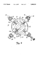
- FIG. 4 is a perspective view of the retractor apparatus in a nested position.
- FIG. 5 is a sectional view, which is taken along a line 5--5 in FIG. 1, illustrating a retractor mounted for adjustment of a vertical pitch of the retractor.
- FIG. 6 is an exploded sectional view of the retractor, which is taken along a line 6--6 in FIG. 5.
- FIG. 7 is a sectional view illustrating an alternative mechanism for mounting a retractor for adjustment of a vertical pitch of the retractor.
- FIG. 8 is an exploded sectional view of the retractor, which is taken along a line 8--8 in FIG. 7.
- the present invention includes a retractor apparatus as illustrated at 10 in FIG. 1.
- the retractor apparatus 10 is used in conducting a surgical operation through an incision 12 made in a patient 14.
- the retractor apparatus 10 includes a retractor support ring 20, a plurality of surgical retractors 22, and a stretchable sleeve 24.
- the retractor support ring 20 retains each of the surgical retractors 22 in a desired position with respect to the incision 12 so that a surgical opening may be formed from the incision 12.
- Each of the surgical retractors 22 are mounted to the retractor support ring 20.
- the surgical retractors 22 are mounted at approximately equal intervals around the retractor support ring 20.
- the mounting of the surgical retractors 22 to the retractor support ring 20 allows each of the surgical retractors 22 to independently move radially inwardly and outwardly with respect to the retractor support ring 20 as indicated by arrow 26.
- the surgical retractors 22 are preferably selected with either a wide retractor blade 30 or a narrow retractor blade 32.
- the surgical retractors 22 with the wide retractor blade 30 are preferably oriented on the retractor support ring 20 opposite each other.
- the surgical retractors 22 with the narrow retractor blade 32 are preferably oriented on the retractor support ring 20 opposite each other.
- Each surgical retractor 22 preferably also includes a threaded rod 34, a radial adjustment controller 36, and a stop mechanism 38 for mounting the retractor blade 30, 32 to the retractor support ring 20.
- the threaded rod 34 has a proximal end 40 and a distal end 42.
- the threaded rod 34 is positioned so that the proximal end 40 extends through an aperture 44 in the retractor support ring 20, as most clearly illustrated in FIG. 2.
- reference to horizontal refers to the typical position of the retractor support ring 20 and the threaded rod 34 lying in a substantially horizontal plane as illustrated in the drawings.
- the retractor support ring 20 and the threaded rod 34 may be positioned in a different manner when actually used depending on the surgical procedure.
- the wide retractor blade 30 is preferably fixedly mounted to the threaded rod 34, as most clearly illustrated in FIG. 2.
- the proximal end 40 of the threaded rod 34 preferably includes an annular projection 50.
- the wide retractor blade 30 has a circular aperture 52 that is adapted to receive the annular projection 50 for fixedly mounting the threaded rod 34 to the wide retractor blade 30.
- the narrow retractor blade 32 is preferably pivotally mounted to the threaded rod 34 to allow the narrow retractor blade 32 to pivot side to side with respect to the threaded rod 34, as most clearly illustrated in FIG. 3.
- the narrow retractor blade 32 is preferably attached to the proximal end 40 of the threaded rod 34 using a blade swivel joint 60.
- the narrow retractor blade 32 is preferably fixedly mounted to the blade swivel joint 60.
- the blade swivel joint 60 preferably includes an annular projection 54.
- the narrow retractor blade 32 has a circular aperture 56 that is adapted to receive the annular projection 54 for fixedly mounting the blade swivel joint 60 to the narrow retractor blade 32.
- the proximal end 40 of the threaded rod 34 includes a reduced diameter section 62.
- the reduced diameter section 62 has an aperture 64 disposed normally to an axis of the threaded rod 34.
- the blade swivel joint 60 has two spaced-apart arm sections 66.
- the spaced-apart arm sections 66 form a recess adapted to receive the reduced diameter section 62.
- Each of the spaced-apart arm sections 66 includes an aperture 68.
- the apertures 68 on each of the spaced-apart area sections 66 are preferably axially aligned.
- the apertures 68 are also oriented on the spaced-apart arm sections 66 so that when the reduced diameter section 62 is placed between the spaced-apart arm sections 66, the apertures 68 are aligned with the aperture 64.
- the blade swivel joint 60 is retained in a pivotal relationship with respect to the threaded rod 34 by inserting a pivot pin 72 through the aligned apertures 64, 68.
- the narrow retractor blades 32 Mounting the narrow retractor blades 32 for side to side pivoting with respect to the threaded rod 34 allows the narrow retractor blades 32 to nest between the wide retractor blades 30, as most clearly illustrated in FIG. 4. Nesting of the narrow retractor blades 32 between the wide retractor blades 30 allows the retractor blades 30, 32 to occupy a smaller profile than if the retractor blades 30, 32 did not nest.
- the capability of the narrow retractor blades 32 to pivot from side to side allows all of the retractor blades 30, 32 to nest more closely into a smaller profile. The smaller profile makes it easier to insert the retractor blades 30, 32 into the incision 12.
- At least one of the wide retractor blades 30 is preferably mounted to the threaded rod 34 to allow the wide retractor blade 30 to pivot such that a vertical pitch of the wide retractor blade 30 is adjustable.
- vertical means a plane that is normal to the substantially horizontal plane of the retractor support ring 20.
- a lower portion 31 of the wide retractor blade 30 moves outwardly with respect to the retractor support ring 20 changing its pitch as most clearly illustrated in FIGS. 5 and 6.
- Vertically pivoting of the wide retractor blade 30 with respect to the threaded rod 34 allows a larger surgical opening to be formed inside the incision 12.
- the larger surgical opening increases a surgeon's field of view while allowing the tissue immediately surrounding the incision 12 to be expanded to a lesser extent.
- the surgical retractor 22 preferably includes a pitch control mechanism 80 for controlling the vertical pitch of the wide retractor blade 30.
- the pitch control mechanism 80 includes a pitch control rod 86 with a male threaded region 88.
- the threaded rod 34 includes a central bore 82 that is adapted to receive the pitch control rod 86.
- the central bore 82 includes a female threaded region 84 that is adapted to engage the male threaded region 88 on the pitch control rod 86. Rotation of the pitch control rod 86 with respect to the threaded rod 34 thereby causes the pitch control rod 86 to move axially with respect to the threaded rod 34 as indicated by arrow 90.
- Rotation of the pitch control rod 86 is preferably controlled by a handle 94.
- the handle 94 preferably has a diameter 96 that is wider than the threaded rod 34 to retain the radial adjustment controller 36 in an assembled configuration with respect to the threaded rod 34.
- the wide retractor blade 30 is removably mounted to the threaded rod 34 with a retractor mounting mechanism 97.
- the retractor mounting mechanism 97 includes a male pivot portion 98 and a female pivot portion 100.
- the male pivot portion 98 and the female pivot portion 100 are pivotally mounted together.
- the male pivot portion 98 includes a reduced diameter portion 102 and an annular projection 104.
- the male pivot portion 98 also includes an aperture 106 disposed normally to a central axis of the male pivot portion 98.
- the wide retractor blade 30 has a circular aperture 110 that is adapted to receive the annular projection 104 for fixedly mounting the male pivot portion 98 to the wide retractor blade 30.
- the proximal end 40 of the threaded rod 34 includes a female threaded region 114.
- the female threaded region 114 having a diameter that is greater than a diameter of the female threaded region 84.
- the female pivot portion 100 includes a male threaded region 115 and two spaced-apart arm sections 116.
- the male threaded region 115 threadably engages the female threaded region 114 of the threaded rod 34 to removably attach the female pivot portion 100 to the threaded rod 34.
- Removably attaching the female pivot portion 100 to the threaded rod 34 allows the wide retractor blade 30 to be readily removed from the threaded rod 34.
- the female pivot portion 100 also includes a central bore 117 extending therethrough.
- the central bore 117 is preferably axially aligned with the central bore 82 through the threaded rod 34 when the female pivot portion 100 threadably engages the threaded rod 34.
- the spaced-apart arm sections 116 form a recess that is adapted to receive the reduced diameter portion 102.
- Each of the spaced-apart arm sections 116 includes an aperture 118.
- the apertures 118 on each of the spaced-apart arm sections 116 are preferably axially aligned.
- the apertures 118 are oriented on the spaced-apart arm sections 116 so that when the reduced diameter portion 102 is placed between the spaced-apart arm sections 116, the apertures 118 are aligned with the aperture 106.
- the female pivot portion 100 is retained in a pivotal relationship with respect to the male pivot portion 98 by inserting a pivot pin 112 through the apertures 106, 118.
- the reduced diameter portion 102 of the male pivot portion 98 includes an angled surface 122.
- an end 120 of the pitch control rod 86 opposite the handle 94 contacts the pivot portion angled surface 122 and causes the male pivot portion 100 to vertically pivot with respect to the female pivot portion 98.
- the female pivot portion 100 includes an angled surface 124 that conforms with the pivot portion angled surface 122. Contact between the angled surface 124 and the pivot portion angled surface 122 limits the extent to which the male pivot portion 98 may pivot with respect to the female pivot portion 100.
- the present invention also includes an alternative mounting mechanism 126 for mounting the wide retractor blade 30 to the threaded rod 34, as most clearly illustrated in FIGS. 7 and 8. Similar to the mounting mechanism 97 illustrated in FIGS. 5 and 6, the alternative mounting mechanism 126 removably mounts the wide retractor blade 30 to the threaded rod 34.
- the mounting mechanism 126 includes a male pivot portion 129 and a female pivot portion 128. The male pivot portion 129 and the female pivot portion 129 are pivotally mounted together.
- the male pivot portion 129 includes a male threaded region 131 and a reduced diameter portion 132.
- the male pivot portion 129 also includes an aperture 134 disposed normally to a central axis of the male pivot portion 129.
- the male threaded region 131 threadably engages the female threaded region 114 of the threaded rod 34 to removably attach the male pivot portion 129 to the threaded rod 34. Removably attaching the male pivot portion 129 to the threaded rod 34 allows the wide retractor blade 30 to be readily removed from the threaded rod 34.
- the male pivot portion 129 also includes a central bore 133 extending therethrough.
- the central bore 133 is preferably axially aligned with the central bore 82 through the threaded rod 34 when the male pivot portion 129 threadably engages the threaded rod 34.
- the female pivot portion 128 includes an annular projection 135 and two spaced-apart arm sections 136.
- the circular aperture 110 in the wide retractor blade 30 is adapted to receive the annular projection 135 for fixedly mounting the female pivot portion 128 to the wide retractor blade 30.
- the spaced-apart arm sections 136 form a recess that is adapted to receive the reduced diameter portion 132.
- Each of the spaced-apart arm sections 136 includes an aperture 137.
- the apertures 137 on each of the spaced-apart arm sections 136 are preferably axially aligned.
- the apertures 137 are also oriented on the spaced-apart arm sections 136 so that when the reduced diameter portion 132 is placed between the spaced-apart arm sections 136, the apertures 137 are aligned with the aperture 134.
- the female pivot portion 128 is retained in a pivotal relationship with respect to the male pivot portion 129 by inserting pivot pins 138 through the apertures 134, 137 on each side of the central bore 133.
- the recess between the spaced-apart arm sections 136 includes an angled surface 139.
- the pitch control rod 86 is rotated with respect to the threaded rod 34, the end 120 of the pitch control rod contacts the angled surface 139 and causes the female pivot portion 128 to vertically pivot with respect to the male pivot portion 129.
- the male pivot portion 129 includes an angled surface 141 that conforms with the angled surface 139. Contact between the angled surface 139 and the angled surface 141 limits the extent to which the female pivot portion 128 may pivot with respect to the male pivot portion 129.
- the narrow retractor blades 32 may be mounted for both side to side pivoting and vertical pitch adjustment and that each of the retractor blades 30, 32 may be removably mounted to the threaded rods 34.
- the radial adjustment controller 36 controls radial movement of the threaded rod 34 with respect to the retractor support ring 20 as indicated by arrow 26 in FIG. 1.
- the radial adjustment controller 36 engages the threaded rod 34 between the proximal end 40 and the distal end 42 proximate to an exterior surface 130 of the retractor support ring 20.
- the radial adjustment controller 36 is capable of operating in a fine adjustment mode and a coarse adjustment mode.
- the radial adjustment controller 36 is preferably biased in the fine adjustment mode.
- the structure of the radial adjustment controller 36 is most clearly illustrated in FIGS. 5 and 6.
- the radial adjustment controller 36 includes a casing portion 140, an engagement portion 142, and a spring 144.
- the casing portion 140 includes an aperture 146 through which the threaded rod 34 is disposed.
- the casing portion 140 also includes a recess 148 that is adapted to receive at least a portion of the engagement portion 142 and the spring 144.
- the engagement portion 142 includes an aperture 149 through which the threaded rod 34 is disposed.
- the aperture has a threaded surface section 150 and a substantially smooth surface section 152.
- the spring 144 biases the engagement portion 142 so that the threaded surface section 150 engages the threaded rod 34.
- the radial adjustment controller 36 is in the fine adjustment mode and the position of the surgical retractor 22 may be radially adjusted by rotating the radial adjustment controller 36 with respect to the threaded rod 34.
- the radial adjustment controller 36 When it is desired to radially adjust the position of the surgical retractor 22 more quickly, the radial adjustment controller 36 is moved to the coarse adjustment mode.
- the coarse adjustment mode is entered by moving the engagement portion 142 with respect to the casing portion 140 as indicated by arrow 160 in FIG. 5 so that the threaded rod 34 is adjacent to the substantially smooth surface section 152.
- the threaded surface section 150 does not engage the threaded rod 34.
- the retractor apparatus 10 preferably also includes at least one spacer 154 mounted to the retractor support ring 20, as most clearly illustrated in FIG. 1.
- the spacer 154 retains the radial adjustment controller 36 a selected distance from the retractor support ring 20.
- the spacer 154 minimizes interference between the radial adjustment controller 36, the retractor support ring 20 or the retractor blades 30, 32 when adjusting the radial position of the retractor blades 30, 32.
- the surgical retractors 22 are preferably retained in an assembled configuration with respect to the retractor support ring 20 by the stop mechanism 38, as most clearly illustrated in FIG. 1. Maintaining the surgical retractors 22 in the assembled configuration is desirable to prevent components of the retractor apparatus 10 from being lost during use or cleaning.
- the stop mechanism 38 is mounted to the distal end 42 of the threaded rod 34.
- the stop mechanism 38 has an outer diameter 148 that is greater than the width of the aperture 146 in the casing portion 140.
- the stop mechanism 38 thereby prevents the radial adjustment controller 36 from becoming detached from the threaded rod 34.
- the stop mechanism 38 By preventing the radial adjustment controller 36 from becoming detached from the threaded rod 34, the stop mechanism 38 thereby retains the surgical retractor 22 on the retractor support ring 20.
- the stretchable sleeve 24 is placed over the retractor blades 30, 32 so that the stretchable sleeve 24 encircles the retractor blades 30, 32.
- the stretchable sleeve 24 thereby forms a continuous surface between the retractor blades 30, 32 and prevents tissue and organs within the incision 12 from interfering with the surgical operation. Because the stretchable sleeve 24 forms a continuous surface between the retractor blades 30, 32, the retractor blades 30, 32 may be selected with narrower widths than previously possible with prior art retractor apparatuses. Forming the retractor blades 30, 32 with narrower widths allows the retractor blades 30, 32 to nest into a smaller profile, which reduces the size of the incision 12 that must be made in the patient.
- the stretchable sleeve 24 is preferably made of a material that is also pliant, such as latex or a silicone elastomer.
- retractor blades were required to be wider than the retractor blades used with the present invention to prevent tissue and organs within the incision from interfering with the surgical operation.
- a drawback of using wider retractor blades is that the incision must be larger than the incision made to insert the retractor blades 30, 32 of the present invention.
- the retractor apparatus 10 is preferably free-floating in the incision 12.
- free floating means that the retractor apparatus 10 is not maintained in the incision 12 by mounting either directly or indirectly to an operating table (not shown).
- the retractor apparatus 10 may also be used in conjunction with a support apparatus (not shown) to retain the retractor apparatus in a stationary position over the patient who is positioned on the operating table.
- the support apparatus is typically attached to side rails (not shown) that are mounted along sides of the operating table with a side rail clamping device.
- a suitable support apparatus and side rail clamping device is described in U.S. Pat. No. 4,355,631, which is assigned to the assignee of the present application and is hereby incorporated by reference.
- the retractor support ring 20 also preferably includes a port 170 for attachment of a light source 172, such as a fiber optic cable, to the retractor support ring 20.
- the port 170 preferably allows the light source 172 to be quickly connected and disconnected from the retractor support ring 20.
- the port 170 also preferably includes a mirror 176 that is mounted proximate to an interior surface 174 of the retractor support ring 20. The mirror 176 reflects light that is delivered from the light source 172 into the incision 12.
Abstract
Description
Claims (32)
Priority Applications (1)
| Application Number | Priority Date | Filing Date | Title |
|---|---|---|---|
| US08/555,265 US5688223A (en) | 1995-11-08 | 1995-11-08 | Retractor support with adjustable retractor blades |
Applications Claiming Priority (1)
| Application Number | Priority Date | Filing Date | Title |
|---|---|---|---|
| US08/555,265 US5688223A (en) | 1995-11-08 | 1995-11-08 | Retractor support with adjustable retractor blades |
Publications (1)
| Publication Number | Publication Date |
|---|---|
| US5688223A true US5688223A (en) | 1997-11-18 |
Family
ID=24216615
Family Applications (1)
| Application Number | Title | Priority Date | Filing Date |
|---|---|---|---|
| US08/555,265 Expired - Lifetime US5688223A (en) | 1995-11-08 | 1995-11-08 | Retractor support with adjustable retractor blades |
Country Status (1)
| Country | Link |
|---|---|
| US (1) | US5688223A (en) |
Cited By (77)
| Publication number | Priority date | Publication date | Assignee | Title |
|---|---|---|---|---|
| US5882298A (en) * | 1998-08-05 | 1999-03-16 | Minnesota Scientific, Inc. | Retractor assembly with connecting pin and method for removably assembling |
| US5951466A (en) * | 1998-04-13 | 1999-09-14 | Viamedics, Llc | Self-seating surgical access device and method of gaining surgical access to a body cavity |
| US6296609B1 (en) | 2000-04-14 | 2001-10-02 | Salvador A. Brau | Surgical retractor and related surgical approach to access the anterior lumbar region |
| US6312377B1 (en) | 2000-04-06 | 2001-11-06 | Viamedics, Llc | Soft tissue compression shield and method of retracting tissue |
| US6416465B2 (en) | 2000-04-14 | 2002-07-09 | Salvador A. Brau | Surgical retractor and related surgical approach to access the anterior lumbar region |
| US6416467B1 (en) * | 2000-09-15 | 2002-07-09 | Mcmillin Matthew | Vaginal speculum and method of using same |
| US20030097045A1 (en) * | 2001-11-20 | 2003-05-22 | Ravindra Kashyap | Multipurpose circular retractor |
| US20040087833A1 (en) * | 2002-10-30 | 2004-05-06 | Thomas Bauer | Retractor |
| US20040097907A1 (en) * | 2001-05-15 | 2004-05-20 | Dipoto Gene P. | Cannula for receiving surgical instruments |
| US6746396B1 (en) | 1999-04-13 | 2004-06-08 | Viamedics, Llc | Self-seating surgical access device and method of use |
| US20040147812A1 (en) * | 2002-10-02 | 2004-07-29 | Hamel Ross J. | Retractor with interchangeable retractor blades |
| US20040176665A1 (en) * | 2002-06-26 | 2004-09-09 | Branch Charles L. | Instruments and methods for minimally invasive tissue retraction and surgery |
| US20050137460A1 (en) * | 2003-11-12 | 2005-06-23 | Bertolero Arthur A. | Retractor with inflatable blades |
| US20050165281A1 (en) * | 2004-01-27 | 2005-07-28 | Sundaram Ravikumar | Surgical retractor apparatus for use with a surgical port |
| US20050215866A1 (en) * | 2004-03-25 | 2005-09-29 | Depuy Spine, Inc. | Surgical retractor positioning device |
| US20050215863A1 (en) * | 2004-01-27 | 2005-09-29 | Sundaram Ravikumar | Surgical retractor apparatus for use with a surgical port |
| US20050245942A1 (en) * | 2003-08-26 | 2005-11-03 | Dipoto Gene P | Adjustable height access device for treating the spine of a patient |
| US20050251192A1 (en) * | 2004-03-31 | 2005-11-10 | Shluzas Alan E | Access device having discrete visualization locations |
| EP1605814A1 (en) * | 2002-12-13 | 2005-12-21 | Synthes Spine Company, L.P. | Guided retractor and methods of use |
| US20060052672A1 (en) * | 2004-09-09 | 2006-03-09 | Landry Michael E | Surgical retraction apparatus method of use |
| US20060106416A1 (en) * | 2004-10-29 | 2006-05-18 | Douglas Raymond | Expandable ports and methods for minimally invasive surgery |
| US20060129033A1 (en) * | 2004-12-15 | 2006-06-15 | Depuy Spine, Inc. | Retractor blade extender tower |
| US20060142642A1 (en) * | 2004-12-29 | 2006-06-29 | Lins Robert E | Minimally-invasive portal system for performing lumbar decompression, instrumented fusion/stabilization, and the like |
| US20060195017A1 (en) * | 2004-11-22 | 2006-08-31 | Shluzas Alan E | Expandable device for providing access to the spine |
| WO2006115893A2 (en) * | 2005-04-22 | 2006-11-02 | Wilk Patent, Llc | Medical port device, kit and associated method |
| US20060272979A1 (en) * | 2005-06-07 | 2006-12-07 | Lubbers Lawrence M | Surgical Tray |
| US20070010819A1 (en) * | 2003-08-30 | 2007-01-11 | Grampian Health Board | Bone fixing device and method for distracting a fracture and jig and method for insertion of a bone fixing device |
| US20070049962A1 (en) * | 1998-12-23 | 2007-03-01 | Nuvasive, Inc. | Nerve surveillance cannulae systems |
| US20070060939A1 (en) * | 2005-09-02 | 2007-03-15 | Zimmer Spine, Inc. | Expandable and retractable cannula |
| US20070083086A1 (en) * | 2005-10-11 | 2007-04-12 | Levahn Intellectual Property Holding Company, Llc | Shaped retractor blade |
| US7226451B2 (en) | 2003-08-26 | 2007-06-05 | Shluzas Alan E | Minimally invasive access device and method |
| WO2007087536A2 (en) * | 2006-01-23 | 2007-08-02 | Pioneer Surgical Technology, Inc. | Retraction apparatus and method of use |
| US20070238932A1 (en) * | 2006-03-08 | 2007-10-11 | Jones Robert J | Surgical retractor and retractor assembly |
| US20080065135A1 (en) * | 1998-12-23 | 2008-03-13 | Nuvasive, Inc. | Nerve surveillance cannulae systems |
| US20080103366A1 (en) * | 2006-10-26 | 2008-05-01 | Endoscopic Technologies, Inc. | Atraumatic tissue retraction device |
| US20080249372A1 (en) * | 2007-03-30 | 2008-10-09 | Joey Camia Reglos | Retractor |
| US20090299148A1 (en) * | 2008-05-30 | 2009-12-03 | John White | Retraction Apparatus and Method of Use |
| US7645232B2 (en) | 2003-05-16 | 2010-01-12 | Zimmer Spine, Inc. | Access device for minimally invasive surgery |
| US20100023117A1 (en) * | 2005-12-15 | 2010-01-28 | Georgia Tech Research Corporation | Papillary muscle position control devices, systems, & methods |
| US20100113885A1 (en) * | 2008-10-30 | 2010-05-06 | Warsaw Orthopedic, Inc. | Retractor assemblies for surgery in a patient |
| US20100152542A1 (en) * | 2006-05-19 | 2010-06-17 | Acorn Cardiovascular, Inc. | Pericardium management method for intra-pericardial surgical procedures |
| US20100268036A1 (en) * | 2009-04-16 | 2010-10-21 | Aesculap Ag | Surgical retraction device |
| US8100828B2 (en) | 2002-11-23 | 2012-01-24 | George Frey | Distraction and retraction system for spinal surgery |
| US8105236B2 (en) * | 2005-07-11 | 2012-01-31 | Kyphon Sarl | Surgical access device, system, and methods of use |
| US8192463B2 (en) | 2007-05-24 | 2012-06-05 | Mcloughlin Joseph | Surgical retractor and related methods |
| US20120245432A1 (en) * | 2006-06-06 | 2012-09-27 | Edward Karpowicz | Surgical Retractor System |
| US20130096387A1 (en) * | 2011-10-18 | 2013-04-18 | Warsaw Orthopedic, Inc. | Surgical retractor assembly and method |
| US20130131456A1 (en) * | 2003-09-25 | 2013-05-23 | Nuvasive, Inc. | Surgical Access System and Related Methods |
| USRE44268E1 (en) | 1997-07-15 | 2013-06-04 | Zimmer Spine, Inc. | Method and instruments for percutaneous arthroscopic disc removal, bone biopsy and fixation of the vertebral |
| US8636656B2 (en) | 2011-08-16 | 2014-01-28 | Warsaw Orthopedic, Inc. | Retractor assemblies with blade drive mechanisms |
| US8663100B2 (en) | 2002-10-08 | 2014-03-04 | Nuvasive, Inc. | Surgical access system and related methods |
| US8672840B2 (en) | 2002-06-26 | 2014-03-18 | Nuvasive, Inc. | Surgical access system and related methods |
| US8696559B2 (en) | 2003-02-27 | 2014-04-15 | Nuvasive, Inc. | Surgical access system and related methods |
| US8728162B2 (en) | 2010-04-15 | 2014-05-20 | Osteomed, Llc | Direct lateral spine system instruments, implants and associated methods |
| US8738123B2 (en) | 2001-09-25 | 2014-05-27 | Nuvasive, Inc. | System and methods for performing surgical procedures and assessments |
| US8747307B2 (en) | 2003-01-16 | 2014-06-10 | Nuvasive, Inc. | Surgical access system and related methods |
| US8790406B1 (en) | 2011-04-01 | 2014-07-29 | William D. Smith | Systems and methods for performing spine surgery |
| US8812116B2 (en) | 2001-07-11 | 2014-08-19 | Nuvasive, Inc. | System and methods for determining nerve proximity, direction, and pathology during surgery |
| US8968192B2 (en) | 2008-06-06 | 2015-03-03 | Warsaw Orthopedic, Inc. | Systems and methods for tissue retraction |
| US8992558B2 (en) | 2008-12-18 | 2015-03-31 | Osteomed, Llc | Lateral access system for the lumbar spine |
| US9084591B2 (en) | 2012-10-23 | 2015-07-21 | Neurostructures, Inc. | Retractor |
| US9113852B2 (en) | 2011-03-08 | 2015-08-25 | Pioneer Surgical Technology, Inc. | Apparatus and method for enlarging an incision |
| US9198765B1 (en) | 2011-10-31 | 2015-12-01 | Nuvasive, Inc. | Expandable spinal fusion implants and related methods |
| US9314152B2 (en) | 2003-09-25 | 2016-04-19 | Nuvasive, Inc. | Surgical access system and related methods |
| USRE46134E1 (en) * | 2002-04-05 | 2016-09-06 | Warsaw Othopedic, Inc. | Devices and methods for percutaneous tissue retraction and surgery |
| US9579095B2 (en) | 2011-03-08 | 2017-02-28 | Pioneer Surgical Technology, Inc. | Apparatus and method for enlarging an incision |
| US9622732B2 (en) | 2004-10-08 | 2017-04-18 | Nuvasive, Inc. | Surgical access system and related methods |
| US9743853B2 (en) | 1999-11-24 | 2017-08-29 | Nuvasive, Inc. | Electromyography system |
| CN107874793A (en) * | 2017-11-27 | 2018-04-06 | 无锡圣诺亚科技有限公司 | Micro-wound tissue dilator |
| US10357239B2 (en) | 2011-03-08 | 2019-07-23 | Pioneer Surgical Technology, Inc. | Apparatus and method for enlarging an incision |
| CN110366059A (en) * | 2019-08-06 | 2019-10-22 | 彭晓艳 | A kind of stage sound installation device |
| US10959860B2 (en) | 2008-12-26 | 2021-03-30 | Pantheon Spinal, Llc | Method of retroperitoneal lateral insertion of spinal implants |
| US11166709B2 (en) | 2016-08-23 | 2021-11-09 | Stryker European Operations Holdings Llc | Instrumentation and methods for the implantation of spinal implants |
| US11191532B2 (en) | 2018-03-30 | 2021-12-07 | Stryker European Operations Holdings Llc | Lateral access retractor and core insertion |
| US11564674B2 (en) | 2019-11-27 | 2023-01-31 | K2M, Inc. | Lateral access system and method of use |
| US11627952B2 (en) | 2020-06-29 | 2023-04-18 | Surgalign Spine Technologies, Inc. | Surgical retractor |
| US11793504B2 (en) | 2011-08-19 | 2023-10-24 | Nuvasive, Inc. | Surgical retractor system and methods of use |
Citations (5)
| Publication number | Priority date | Publication date | Assignee | Title |
|---|---|---|---|---|
| US1157202A (en) * | 1913-10-14 | 1915-10-19 | Uri C Bates | Surgical apparatus. |
| US1400616A (en) * | 1921-01-10 | 1921-12-20 | Harvey B Mccrory | Abdominal retractor |
| US1706500A (en) * | 1927-08-01 | 1929-03-26 | Henry J Smith | Surgical retractor |
| US2623517A (en) * | 1950-06-29 | 1952-12-30 | Barlow Israel Owen | Surgical abdominal retractor |
| US3522799A (en) * | 1967-06-21 | 1970-08-04 | William K Gauthier | Surgical retractor device |
-
1995
- 1995-11-08 US US08/555,265 patent/US5688223A/en not_active Expired - Lifetime
Patent Citations (5)
| Publication number | Priority date | Publication date | Assignee | Title |
|---|---|---|---|---|
| US1157202A (en) * | 1913-10-14 | 1915-10-19 | Uri C Bates | Surgical apparatus. |
| US1400616A (en) * | 1921-01-10 | 1921-12-20 | Harvey B Mccrory | Abdominal retractor |
| US1706500A (en) * | 1927-08-01 | 1929-03-26 | Henry J Smith | Surgical retractor |
| US2623517A (en) * | 1950-06-29 | 1952-12-30 | Barlow Israel Owen | Surgical abdominal retractor |
| US3522799A (en) * | 1967-06-21 | 1970-08-04 | William K Gauthier | Surgical retractor device |
Cited By (179)
| Publication number | Priority date | Publication date | Assignee | Title |
|---|---|---|---|---|
| USRE44268E1 (en) | 1997-07-15 | 2013-06-04 | Zimmer Spine, Inc. | Method and instruments for percutaneous arthroscopic disc removal, bone biopsy and fixation of the vertebral |
| US5951466A (en) * | 1998-04-13 | 1999-09-14 | Viamedics, Llc | Self-seating surgical access device and method of gaining surgical access to a body cavity |
| US6488620B1 (en) | 1998-04-13 | 2002-12-03 | Viamedics, Llc | Self-seating surgical access device |
| US5882298A (en) * | 1998-08-05 | 1999-03-16 | Minnesota Scientific, Inc. | Retractor assembly with connecting pin and method for removably assembling |
| US20070049962A1 (en) * | 1998-12-23 | 2007-03-01 | Nuvasive, Inc. | Nerve surveillance cannulae systems |
| US9014776B2 (en) | 1998-12-23 | 2015-04-21 | Nuvasive, Inc. | Surgical access and nerve surveillance |
| US20080065135A1 (en) * | 1998-12-23 | 2008-03-13 | Nuvasive, Inc. | Nerve surveillance cannulae systems |
| US6746396B1 (en) | 1999-04-13 | 2004-06-08 | Viamedics, Llc | Self-seating surgical access device and method of use |
| US9743853B2 (en) | 1999-11-24 | 2017-08-29 | Nuvasive, Inc. | Electromyography system |
| US6312377B1 (en) | 2000-04-06 | 2001-11-06 | Viamedics, Llc | Soft tissue compression shield and method of retracting tissue |
| US6416465B2 (en) | 2000-04-14 | 2002-07-09 | Salvador A. Brau | Surgical retractor and related surgical approach to access the anterior lumbar region |
| US6296609B1 (en) | 2000-04-14 | 2001-10-02 | Salvador A. Brau | Surgical retractor and related surgical approach to access the anterior lumbar region |
| US6416467B1 (en) * | 2000-09-15 | 2002-07-09 | Mcmillin Matthew | Vaginal speculum and method of using same |
| US7985218B2 (en) | 2001-05-15 | 2011-07-26 | Zimmer Spine, Inc. | Structure for receiving surgical instruments |
| US20040097907A1 (en) * | 2001-05-15 | 2004-05-20 | Dipoto Gene P. | Cannula for receiving surgical instruments |
| US7766930B2 (en) | 2001-05-15 | 2010-08-03 | Zimmer Spine, Inc. | Cannula for receiving surgical instruments |
| US8007492B2 (en) | 2001-05-15 | 2011-08-30 | Zimmer Spine, Inc. | Cannula for receiving surgical instruments |
| US7144393B2 (en) | 2001-05-15 | 2006-12-05 | Dipoto Gene P | Structure for receiving surgical instruments |
| US9037250B2 (en) | 2001-07-11 | 2015-05-19 | Nuvasive, Inc. | System and methods for determining nerve proximity, direction and pathology during surgery |
| US9931077B2 (en) | 2001-07-11 | 2018-04-03 | Nuvasive, Inc. | System and methods for determining nerve proximity, direction and pathology during surgery |
| US10716509B2 (en) | 2001-07-11 | 2020-07-21 | Nuvasive, Inc. | System and methods for determining nerve proximity, direction and pathology during surgery |
| US9456783B2 (en) | 2001-07-11 | 2016-10-04 | Nuvasive, Inc. | System and methods for determining nerve proximity, direction and pathology during surgery |
| US8812116B2 (en) | 2001-07-11 | 2014-08-19 | Nuvasive, Inc. | System and methods for determining nerve proximity, direction, and pathology during surgery |
| US8977352B2 (en) | 2001-09-25 | 2015-03-10 | Nuvasive, Inc. | Systems and methods for performing surgical procedures and assessments |
| US8768450B2 (en) | 2001-09-25 | 2014-07-01 | Nuvasive, Inc. | System and methods for performing surgical procedures and assessments |
| US8738123B2 (en) | 2001-09-25 | 2014-05-27 | Nuvasive, Inc. | System and methods for performing surgical procedures and assessments |
| US10507120B2 (en) | 2001-09-25 | 2019-12-17 | Nuvasive, Inc. | Systems and methods for performing surgical procedures and assessments |
| US20030097045A1 (en) * | 2001-11-20 | 2003-05-22 | Ravindra Kashyap | Multipurpose circular retractor |
| US6932764B2 (en) * | 2001-11-20 | 2005-08-23 | Ravindra Kashyap | Multipurpose circular retractor |
| USRE46403E1 (en) * | 2002-04-05 | 2017-05-16 | Warsaw Orthopedic, Inc. | Devices and methods for percutaneous tissue retraction and surgery |
| USRE46148E1 (en) * | 2002-04-05 | 2016-09-20 | Warsaw Orthopedic, Inc. | Devices and methods for percutaneous tissue retraction and surgery |
| USRE46134E1 (en) * | 2002-04-05 | 2016-09-06 | Warsaw Othopedic, Inc. | Devices and methods for percutaneous tissue retraction and surgery |
| US9750490B2 (en) | 2002-06-26 | 2017-09-05 | Nuvasive, Inc. | Surgical access system and related methods |
| US9848861B2 (en) | 2002-06-26 | 2017-12-26 | Nuvasive, Inc. | Surgical access system and related methods |
| US20040176665A1 (en) * | 2002-06-26 | 2004-09-09 | Branch Charles L. | Instruments and methods for minimally invasive tissue retraction and surgery |
| US10980524B2 (en) | 2002-06-26 | 2021-04-20 | Nuvasive, Inc. | Surgical access system and related methods |
| US8672840B2 (en) | 2002-06-26 | 2014-03-18 | Nuvasive, Inc. | Surgical access system and related methods |
| US8915846B2 (en) | 2002-06-26 | 2014-12-23 | Nuvasive, Inc. | Surgical access system and related methods |
| US9826968B2 (en) | 2002-06-26 | 2017-11-28 | Nuvasive, Inc. | Surgical access system and related methods |
| US8708899B2 (en) | 2002-06-26 | 2014-04-29 | Nuvasive, Inc. | Surgical access system and related methods |
| US7513869B2 (en) | 2002-06-26 | 2009-04-07 | Warsaw Orthopedic, Inc. | Instruments and methods for minimally invasive tissue retraction and surgery |
| US9833227B2 (en) | 2002-06-26 | 2017-12-05 | Nuvasive, Inc. | Surgical access system and related methods |
| US10251633B2 (en) | 2002-06-26 | 2019-04-09 | Nuvasive, Inc. | Surgical access system and related methods |
| US20040147812A1 (en) * | 2002-10-02 | 2004-07-29 | Hamel Ross J. | Retractor with interchangeable retractor blades |
| US7766825B2 (en) * | 2002-10-02 | 2010-08-03 | Synthes Usa, Llc | Retractor with interchangeable retractor blades |
| US9820729B2 (en) | 2002-10-08 | 2017-11-21 | Nuvasive, Inc. | Surgical access system and related methods |
| US9572562B2 (en) | 2002-10-08 | 2017-02-21 | Nuvasive, Inc. | Surgical access system and related methods |
| US9204871B2 (en) | 2002-10-08 | 2015-12-08 | Nuvasive, Inc. | Surgical access system and related methods |
| US10695044B2 (en) | 2002-10-08 | 2020-06-30 | Nuvasive, Inc. | Surgical access system and related methods |
| US8956283B2 (en) | 2002-10-08 | 2015-02-17 | Nuvasive, Inc. | Surgical access system and related methods |
| US8663100B2 (en) | 2002-10-08 | 2014-03-04 | Nuvasive, Inc. | Surgical access system and related methods |
| US8679006B2 (en) | 2002-10-08 | 2014-03-25 | Nuvasive, Inc. | Surgical access system and related methods |
| US20040087833A1 (en) * | 2002-10-30 | 2004-05-06 | Thomas Bauer | Retractor |
| US8100828B2 (en) | 2002-11-23 | 2012-01-24 | George Frey | Distraction and retraction system for spinal surgery |
| EP1605814A4 (en) * | 2002-12-13 | 2006-12-13 | Synthes Spine Company L P | Guided retractor and methods of use |
| EP1605814A1 (en) * | 2002-12-13 | 2005-12-21 | Synthes Spine Company, L.P. | Guided retractor and methods of use |
| US9301743B2 (en) | 2003-01-16 | 2016-04-05 | Nuvasive, Inc. | Surgical access system and related methods |
| US8747307B2 (en) | 2003-01-16 | 2014-06-10 | Nuvasive, Inc. | Surgical access system and related methods |
| US11219440B2 (en) | 2003-01-16 | 2022-01-11 | Nuvasive, Inc. | Surgical access system and related methods |
| US10357238B2 (en) | 2003-01-16 | 2019-07-23 | Nuvasive, Inc. | Surgical access system and related methods |
| US9795371B2 (en) | 2003-01-16 | 2017-10-24 | Nuvasive, Inc. | Surgical access system and related methods |
| US8753270B2 (en) | 2003-01-16 | 2014-06-17 | Nuvasive, Inc. | Surgical access system and related methods |
| US9468405B2 (en) | 2003-02-27 | 2016-10-18 | Nuvasive, Inc. | Surgical access system and related methods |
| US8696559B2 (en) | 2003-02-27 | 2014-04-15 | Nuvasive, Inc. | Surgical access system and related methods |
| US7645232B2 (en) | 2003-05-16 | 2010-01-12 | Zimmer Spine, Inc. | Access device for minimally invasive surgery |
| US20050245942A1 (en) * | 2003-08-26 | 2005-11-03 | Dipoto Gene P | Adjustable height access device for treating the spine of a patient |
| US7736305B2 (en) | 2003-08-26 | 2010-06-15 | Zimmer Spine, Inc. | Adjustable height access device for treating the spine of a patient |
| US7691120B2 (en) | 2003-08-26 | 2010-04-06 | Zimmer Spine, Inc. | Access systems and methods for minimally invasive surgery |
| US20050273133A1 (en) * | 2003-08-26 | 2005-12-08 | Shluzas Alan E | Access systems and methods for minimally invasive surgery |
| US7179225B2 (en) | 2003-08-26 | 2007-02-20 | Shluzas Alan E | Access systems and methods for minimally invasive surgery |
| US7976464B2 (en) | 2003-08-26 | 2011-07-12 | Zimmer Spine, Inc. | Access systems and methods for minimally invasive surgery |
| US7226451B2 (en) | 2003-08-26 | 2007-06-05 | Shluzas Alan E | Minimally invasive access device and method |
| US20050273131A1 (en) * | 2003-08-26 | 2005-12-08 | Shluzas Alan E | Access systems and methods for minimally invasive surgery |
| US20070010819A1 (en) * | 2003-08-30 | 2007-01-11 | Grampian Health Board | Bone fixing device and method for distracting a fracture and jig and method for insertion of a bone fixing device |
| US9314152B2 (en) | 2003-09-25 | 2016-04-19 | Nuvasive, Inc. | Surgical access system and related methods |
| US8942801B2 (en) | 2003-09-25 | 2015-01-27 | Nuvasive, Inc. | Surgical access system and related methods |
| US9265493B2 (en) | 2003-09-25 | 2016-02-23 | Nuvasive, Inc. | Surgical access system and related methods |
| US9610071B2 (en) | 2003-09-25 | 2017-04-04 | Nuvasive, Inc. | Surgical access system and related methods |
| US8764649B2 (en) | 2003-09-25 | 2014-07-01 | Nuvasive, Inc. | Surgical access system and related methods |
| US8753271B1 (en) | 2003-09-25 | 2014-06-17 | Nuvasive, Inc. | Surgical access system and related methods |
| US9788822B2 (en) | 2003-09-25 | 2017-10-17 | Nuvasive, Inc. | Surgical access system and related methods |
| US9974531B2 (en) | 2003-09-25 | 2018-05-22 | Nuvasive, Inc. | Surgical access system and related methods |
| US20170156580A1 (en) * | 2003-09-25 | 2017-06-08 | Nuvasive, Inc. | Surgical access system and related methods |
| US20130131456A1 (en) * | 2003-09-25 | 2013-05-23 | Nuvasive, Inc. | Surgical Access System and Related Methods |
| US8945004B2 (en) | 2003-09-25 | 2015-02-03 | Nuvasive, Inc. | Surgical access system and related methods |
| US8821396B1 (en) | 2003-09-25 | 2014-09-02 | Nuvasive, Inc. | Surgical access system and related methods |
| US8556808B2 (en) * | 2003-09-25 | 2013-10-15 | Nuvasive, Inc. | Surgical access system and related methods |
| US10357233B2 (en) * | 2003-09-25 | 2019-07-23 | Nuvasive, Inc. | Surgical access system and related methods |
| US8628469B2 (en) | 2003-09-25 | 2014-01-14 | Nuvasive, Inc. | Surgical access system and related methods |
| US10653308B2 (en) | 2003-10-17 | 2020-05-19 | Nuvasive, Inc. | Surgical access system and related methods |
| US7294103B2 (en) * | 2003-11-12 | 2007-11-13 | Endoscopic Technologies, Inc. | Retractor with inflatable blades |
| US20050137460A1 (en) * | 2003-11-12 | 2005-06-23 | Bertolero Arthur A. | Retractor with inflatable blades |
| US20050165281A1 (en) * | 2004-01-27 | 2005-07-28 | Sundaram Ravikumar | Surgical retractor apparatus for use with a surgical port |
| US20050215863A1 (en) * | 2004-01-27 | 2005-09-29 | Sundaram Ravikumar | Surgical retractor apparatus for use with a surgical port |
| US7344495B2 (en) | 2004-01-27 | 2008-03-18 | Arvik Enterprises, Llc | Surgical retractor apparatus for use with a surgical port |
| US7195592B2 (en) | 2004-01-27 | 2007-03-27 | Sundaram Ravikumar | Surgical retractor apparatus for use with a surgical port |
| US20090018401A1 (en) * | 2004-03-25 | 2009-01-15 | Depuy Spine, Inc. | Surgical retractor positioning device |
| US7435219B2 (en) | 2004-03-25 | 2008-10-14 | Depuy Spine, Inc. | Surgical retractor positioning device |
| US20050215866A1 (en) * | 2004-03-25 | 2005-09-29 | Depuy Spine, Inc. | Surgical retractor positioning device |
| US20060069404A1 (en) * | 2004-03-31 | 2006-03-30 | Shluzas Alan E | Access device having discrete visualization locations |
| US20050251192A1 (en) * | 2004-03-31 | 2005-11-10 | Shluzas Alan E | Access device having discrete visualization locations |
| US20060052672A1 (en) * | 2004-09-09 | 2006-03-09 | Landry Michael E | Surgical retraction apparatus method of use |
| US7556600B2 (en) * | 2004-09-09 | 2009-07-07 | Zimmer Spine, Inc. | Surgical retraction apparatus and associated methods |
| US11723644B2 (en) | 2004-10-08 | 2023-08-15 | Nuvasive, Inc. | Surgical access system and related methods |
| US9622732B2 (en) | 2004-10-08 | 2017-04-18 | Nuvasive, Inc. | Surgical access system and related methods |
| US7594888B2 (en) | 2004-10-29 | 2009-09-29 | Depuy Spine, Inc. | Expandable ports and methods for minimally invasive surgery |
| US20060106416A1 (en) * | 2004-10-29 | 2006-05-18 | Douglas Raymond | Expandable ports and methods for minimally invasive surgery |
| US20060195017A1 (en) * | 2004-11-22 | 2006-08-31 | Shluzas Alan E | Expandable device for providing access to the spine |
| US9357908B2 (en) * | 2004-12-15 | 2016-06-07 | DePuy Synthes Products, Inc. | Retractor blade extender tower |
| US20100041956A1 (en) * | 2004-12-15 | 2010-02-18 | Frasier William J | Retractor blade extender tower |
| US7625339B2 (en) * | 2004-12-15 | 2009-12-01 | Depuy Spine, Inc. | Retractor blade extender tower |
| US20060129033A1 (en) * | 2004-12-15 | 2006-06-15 | Depuy Spine, Inc. | Retractor blade extender tower |
| US8568305B2 (en) * | 2004-12-29 | 2013-10-29 | Us Spine, Inc. | Minimally-invasive portal system for performing lumbar decompression, instrumented fusion/stabilization, and the like |
| US20060142642A1 (en) * | 2004-12-29 | 2006-06-29 | Lins Robert E | Minimally-invasive portal system for performing lumbar decompression, instrumented fusion/stabilization, and the like |
| US9265491B2 (en) | 2004-12-29 | 2016-02-23 | U.S. Spine, Inc. | Minimally-invasive portal methods for performing lumbar decompression, instrumented fusion/stabilization, and the like |
| WO2006115893A2 (en) * | 2005-04-22 | 2006-11-02 | Wilk Patent, Llc | Medical port device, kit and associated method |
| WO2006115893A3 (en) * | 2005-04-22 | 2007-07-12 | Wilk Patent Llc | Medical port device, kit and associated method |
| US20060252997A1 (en) * | 2005-04-22 | 2006-11-09 | Wilk Patent, Llc | Medical port device, kit and associated method |
| US20060272979A1 (en) * | 2005-06-07 | 2006-12-07 | Lubbers Lawrence M | Surgical Tray |
| US8105236B2 (en) * | 2005-07-11 | 2012-01-31 | Kyphon Sarl | Surgical access device, system, and methods of use |
| US20070060939A1 (en) * | 2005-09-02 | 2007-03-15 | Zimmer Spine, Inc. | Expandable and retractable cannula |
| US20070083086A1 (en) * | 2005-10-11 | 2007-04-12 | Levahn Intellectual Property Holding Company, Llc | Shaped retractor blade |
| US9125742B2 (en) * | 2005-12-15 | 2015-09-08 | Georgia Tech Research Foundation | Papillary muscle position control devices, systems, and methods |
| US20100023117A1 (en) * | 2005-12-15 | 2010-01-28 | Georgia Tech Research Corporation | Papillary muscle position control devices, systems, & methods |
| US8956285B2 (en) * | 2006-01-23 | 2015-02-17 | Pioneer Surgical Technology, Inc. | Retraction apparatus and method of use |
| WO2007087536A2 (en) * | 2006-01-23 | 2007-08-02 | Pioneer Surgical Technology, Inc. | Retraction apparatus and method of use |
| US20070203399A1 (en) * | 2006-01-23 | 2007-08-30 | Gephart Matthew P | Retraction Apparatus and Method of Use |
| WO2007087536A3 (en) * | 2006-01-23 | 2008-01-31 | Pioneer Surgical Technology | Retraction apparatus and method of use |
| US20090069635A1 (en) * | 2006-01-23 | 2009-03-12 | Pioneer Surgical Technology, Inc. | Retraction Apparatus And Method Of Use |
| US7985179B2 (en) * | 2006-01-23 | 2011-07-26 | Pioneer Surgical Technology | Retraction apparatus and method of use |
| US8876687B2 (en) * | 2006-03-08 | 2014-11-04 | Zimmer Spine, Inc. | Surgical retractor and retractor assembly |
| US20070238932A1 (en) * | 2006-03-08 | 2007-10-11 | Jones Robert J | Surgical retractor and retractor assembly |
| US20100152542A1 (en) * | 2006-05-19 | 2010-06-17 | Acorn Cardiovascular, Inc. | Pericardium management method for intra-pericardial surgical procedures |
| US8246539B2 (en) * | 2006-05-19 | 2012-08-21 | Mardil, Inc. | Pericardium management method for intra-pericardial surgical procedures |
| US9993239B2 (en) * | 2006-06-06 | 2018-06-12 | Globus Medical, Inc. | Surgical retractor system |
| US9649101B2 (en) * | 2006-06-06 | 2017-05-16 | Globus Medical, Inc. | Surgical retractor system |
| US20150164496A1 (en) * | 2006-06-06 | 2015-06-18 | Globus Medical, Inc. | Surgical retractor system |
| US20170273679A1 (en) * | 2006-06-06 | 2017-09-28 | Globus Medical, Inc. | Surgical retractor system |
| US8992425B2 (en) * | 2006-06-06 | 2015-03-31 | Globus Medical, Inc. | Surgical retractor system |
| US20120245432A1 (en) * | 2006-06-06 | 2012-09-27 | Edward Karpowicz | Surgical Retractor System |
| US20080103366A1 (en) * | 2006-10-26 | 2008-05-01 | Endoscopic Technologies, Inc. | Atraumatic tissue retraction device |
| US7909761B2 (en) | 2006-10-26 | 2011-03-22 | Endoscopic Technologies, Inc. | Atraumatic tissue retraction device |
| US8206293B2 (en) | 2007-03-30 | 2012-06-26 | Exactech, Inc. | Retractor |
| US20080249372A1 (en) * | 2007-03-30 | 2008-10-09 | Joey Camia Reglos | Retractor |
| US8192463B2 (en) | 2007-05-24 | 2012-06-05 | Mcloughlin Joseph | Surgical retractor and related methods |
| US8523770B2 (en) | 2007-05-24 | 2013-09-03 | Joseph McLoughlin | Surgical retractor and related methods |
| US8262570B2 (en) | 2008-05-30 | 2012-09-11 | Pioneer Surgical Technology, Inc. | Retraction apparatus and method of use |
| US20090299148A1 (en) * | 2008-05-30 | 2009-12-03 | John White | Retraction Apparatus and Method of Use |
| US8968192B2 (en) | 2008-06-06 | 2015-03-03 | Warsaw Orthopedic, Inc. | Systems and methods for tissue retraction |
| US20100113885A1 (en) * | 2008-10-30 | 2010-05-06 | Warsaw Orthopedic, Inc. | Retractor assemblies for surgery in a patient |
| US8226554B2 (en) | 2008-10-30 | 2012-07-24 | Warsaw Orthopedic, Inc. | Retractor assemblies for surgery in a patient |
| US11925342B2 (en) | 2008-12-18 | 2024-03-12 | Howmedica Osteonics Corp. | Lateral access system for the lumbar spine |
| US8992558B2 (en) | 2008-12-18 | 2015-03-31 | Osteomed, Llc | Lateral access system for the lumbar spine |
| US10687797B2 (en) | 2008-12-18 | 2020-06-23 | Howmedica Osteonics Corp. | Lateral access system for the lumbar spine |
| US10959860B2 (en) | 2008-12-26 | 2021-03-30 | Pantheon Spinal, Llc | Method of retroperitoneal lateral insertion of spinal implants |
| US20100268036A1 (en) * | 2009-04-16 | 2010-10-21 | Aesculap Ag | Surgical retraction device |
| US8728162B2 (en) | 2010-04-15 | 2014-05-20 | Osteomed, Llc | Direct lateral spine system instruments, implants and associated methods |
| US9579095B2 (en) | 2011-03-08 | 2017-02-28 | Pioneer Surgical Technology, Inc. | Apparatus and method for enlarging an incision |
| US11172919B2 (en) | 2011-03-08 | 2021-11-16 | Pioneer Surgical Technology, Inc. | Apparatus and method for enlarging an incision |
| US10357239B2 (en) | 2011-03-08 | 2019-07-23 | Pioneer Surgical Technology, Inc. | Apparatus and method for enlarging an incision |
| US9980714B2 (en) | 2011-03-08 | 2018-05-29 | Pioneer Surgical Technology, Inc. | Apparatus and method for enlarging an incision |
| US9113852B2 (en) | 2011-03-08 | 2015-08-25 | Pioneer Surgical Technology, Inc. | Apparatus and method for enlarging an incision |
| US8790406B1 (en) | 2011-04-01 | 2014-07-29 | William D. Smith | Systems and methods for performing spine surgery |
| US9949840B1 (en) | 2011-04-01 | 2018-04-24 | William D. Smith | Systems and methods for performing spine surgery |
| US8636656B2 (en) | 2011-08-16 | 2014-01-28 | Warsaw Orthopedic, Inc. | Retractor assemblies with blade drive mechanisms |
| US11793504B2 (en) | 2011-08-19 | 2023-10-24 | Nuvasive, Inc. | Surgical retractor system and methods of use |
| US9592041B2 (en) * | 2011-10-18 | 2017-03-14 | Warsaw Orthopedic, Inc. | Surgical retractor assembly and method |
| US20130096387A1 (en) * | 2011-10-18 | 2013-04-18 | Warsaw Orthopedic, Inc. | Surgical retractor assembly and method |
| US9655744B1 (en) | 2011-10-31 | 2017-05-23 | Nuvasive, Inc. | Expandable spinal fusion implants and related methods |
| US9198765B1 (en) | 2011-10-31 | 2015-12-01 | Nuvasive, Inc. | Expandable spinal fusion implants and related methods |
| US9084591B2 (en) | 2012-10-23 | 2015-07-21 | Neurostructures, Inc. | Retractor |
| US11166709B2 (en) | 2016-08-23 | 2021-11-09 | Stryker European Operations Holdings Llc | Instrumentation and methods for the implantation of spinal implants |
| CN107874793A (en) * | 2017-11-27 | 2018-04-06 | 无锡圣诺亚科技有限公司 | Micro-wound tissue dilator |
| US11191532B2 (en) | 2018-03-30 | 2021-12-07 | Stryker European Operations Holdings Llc | Lateral access retractor and core insertion |
| US11911016B2 (en) | 2018-03-30 | 2024-02-27 | Stryker European Operations Holdings Llc | Lateral access retractor and core insertion |
| CN110366059B (en) * | 2019-08-06 | 2020-09-29 | 浦江县汕淋贸易有限公司 | Stereo set installation device for stage |
| CN110366059A (en) * | 2019-08-06 | 2019-10-22 | 彭晓艳 | A kind of stage sound installation device |
| US11564674B2 (en) | 2019-11-27 | 2023-01-31 | K2M, Inc. | Lateral access system and method of use |
| US11627952B2 (en) | 2020-06-29 | 2023-04-18 | Surgalign Spine Technologies, Inc. | Surgical retractor |
Similar Documents
| Publication | Publication Date | Title |
|---|---|---|
| US5688223A (en) | Retractor support with adjustable retractor blades | |
| US6074343A (en) | Surgical tissue retractor | |
| US4457300A (en) | Surgical retractor | |
| EP1269922B1 (en) | Articulated and lockable suture retaining retractor ring | |
| US5171254A (en) | Eye fixation device | |
| US4911160A (en) | Apparatus for laser surgery on a patient lying on an operating table | |
| US5284129A (en) | Swivel ring surgical retractor | |
| US5810712A (en) | Surgical endoscope support and pivot | |
| US5902233A (en) | Angling surgical retractor apparatus and method of retracting anatomy | |
| US4390011A (en) | Adjustable surgical arm rest and instrument platform | |
| US5195506A (en) | Surgical retractor for puncture operation | |
| US20010041828A1 (en) | Surgical retractor | |
| US4865484A (en) | Single release, multiple axis coupling | |
| US6811558B2 (en) | Method for performing a surgical procedure and a cannula for use in performing the surgical procedure | |
| US6592573B2 (en) | Through-port heart stabilization system | |
| US5520608A (en) | Orthopaedic retractor blade | |
| EP3116462B1 (en) | Limb positioning system | |
| US7658729B2 (en) | Attachment device and system for corneal irrigating cannula and method thereof | |
| JPH08501955A (en) | Rocking swivel surgery orifice | |
| US11497670B2 (en) | Surgical mask positioning system | |
| ES2102577T3 (en) | REMOTE CONTROLLED ROBOT WITH MOVEMENT AROUND A CENTRAL POINT FOR SURGERY. | |
| EP0641177A1 (en) | Bladed endoscopic retractor | |
| BRPI0618138B1 (en) | Extendable wide-angle surgical lighting system and wide-angle extendable illuminator | |
| EP2911625B1 (en) | Adjustable loop fiber optic illumination device for surgery | |
| US6138304A (en) | Adjustable surgical support |
Legal Events
| Date | Code | Title | Description |
|---|---|---|---|
| AS | Assignment |
Owner name: MINNESOTA SCIENTIFIC, INC., MINNESOTA Free format text: ASSIGNMENT OF ASSIGNORS INTEREST;ASSIGNOR:ROSENDAHL, PETER R.;REEL/FRAME:007787/0004 Effective date: 19951031 |
|
| STCF | Information on status: patent grant |
Free format text: PATENTED CASE |
|
| CC | Certificate of correction | ||
| REMI | Maintenance fee reminder mailed | ||
| FPAY | Fee payment |
Year of fee payment: 4 |
|
| SULP | Surcharge for late payment | ||
| FPAY | Fee payment |
Year of fee payment: 8 |
|
| FEPP | Fee payment procedure |
Free format text: PAT HOLDER NO LONGER CLAIMS SMALL ENTITY STATUS, ENTITY STATUS SET TO UNDISCOUNTED (ORIGINAL EVENT CODE: STOL); ENTITY STATUS OF PATENT OWNER: LARGE ENTITY |
|
| FPAY | Fee payment |
Year of fee payment: 12 |
|
| FEPP | Fee payment procedure |
Free format text: PAYER NUMBER DE-ASSIGNED (ORIGINAL EVENT CODE: RMPN); ENTITY STATUS OF PATENT OWNER: LARGE ENTITY Free format text: PAYOR NUMBER ASSIGNED (ORIGINAL EVENT CODE: ASPN); ENTITY STATUS OF PATENT OWNER: LARGE ENTITY |