Technical Field
-
The present invention relates to zoom lenses and electronic still
cameras using the same. More specifically, it relates to zoom lenses
with high picture quality used in electronic still cameras and to
electronic still cameras using these zoom lenses.
Background Art
-
As personal computers have become more developed and
widespread, electronic still cameras quickly have gained popularity as
image input devices. The total pixel number of the solid-state imaging
elements used in electronic still cameras has exceeded 1 million pixels,
and recently electronic still cameras provided with solid-state imaging
elements having a total pixel number greater than 3 million pixels also
have appeared on the market. Video cameras that are capable of
capturing high-quality still images in addition to moving pictures also
have appeared on the market.
-
The optical system of electronic still cameras is provided with a
taking lens, an optical low-pass filter, and a solid-state imaging element
arranged in that order from the object side to the image plane side. The
taking lens forms on the imaging surface of the solid-state imaging
element an actual image that corresponds to an object. The solid-state
imaging element carries out spatial sampling depending on the pixel
structure, and outputs an image signal of the image formed on the
imaging surface. The solid-state imaging element is thin, lightweight,
and compact, and therefore the electronic still camera can be made
compact.
-
Solid-state imaging elements perform spatial sampling depending
on the pixel structure, however, an optical low-pass filter is typically
disposed between a zoom lens, which serves as the taking lens, and the
solid-state imaging element to remove the aliasing distortion that occurs
at this time, removing high-frequency components from the image
formed by the zoom lens. Typically, optical low-pass filters are made of
a quartz plate. Here, the characteristic that is exploited is that when
natural light is incident on the quartz plate, the natural light is split
into an ordinary ray and an extraordinary ray due to the birefringence of
the quartz, and these are emitted parallel to one another.
-
With solid-state imaging elements, when the pixel number is
increased but the picture plane size is kept the same, the pixel pitch
becomes small, lowering the aperture ratio and the photosensitivity
Accordingly, by providing a miniature positive lens at each pixel of the
solid-state imaging element, the effective aperture ratio is increased,
preventing a drop in the photosensitivity. In this case, to allow most of
the light emitted from the miniature positive lenses to arrive at
corresponding pixels, it is necessary to configure the zoom lens so that
the principle rays that are incident on the pixels are substantially
parallel to the optical axis. That is, there must be good telecentricity.
-
Although electronic still cameras come in many forms, one
example is a compact type electronic still camera provided with a zoom
lens having a ×2 to ×3 zoom ratio. One demand on compact type
electronic still cameras is that they be easy to carry, and it is necessary
that the optical total length at least when not in use (the distance from
the apex of the lens surface most on the object side of the overall lens
system to the imaging surface of the solid-state imaging element) is
short.
-
A zoom lens that is conceivably suited to meet these demands is a
two-group zoom lens constituted by a first lens group having a negative
power and a second lens group having a positive power arranged in that
order from the object side to the image plane side, which performs
zooming by changing the spacing between these two lens groups.
However, a characteristic of such zoom lenses composed of two lens
groups is that they are suited for wide angles, and thus have the problem
of a small zoom ratio of about ×2. Also, to perform focus adjustment, it
is necessary to move at least one of the two lens groups, but since both
lens groups are large and heavy, there is also the problem that two-group
zoom lenses as described above are not suited for autofocus.
Accordingly, to solve these problems, many proposals have been made for
zoom lenses constituted by three lens groups, in which a third lens group
having a positive power is disposed on the image plane side of a zoom
lens having two lens groups.
-
For example, JP H11-194274A discloses a zoom lens constituted
by three lens groups, these being a first lens group, arranged in that
order from the object side in a negative, positive power arrangement, a
second lens group constituted by four lenses, and a third lens group
constituted by a single lens. Also, JP 2001-296475A discloses a zoom
lens constituted by three lens groups, these being a first lens group,
arranged in that order from the object side in a negative, positive power
arrangement or in a negative, negative, positive power arrangement, a
second lens group constituted by four lenses, and a third lens group
constituted by a single lens or a single cemented lens.
-
These zoom lenses constituted by three lens groups are made of a
first lens group having a negative power, a second lens group having a
positive power, and a third lens group having a positive power, arranged
in that order from the object side to the image plane side. When
zooming from the wide-angle end to the tele end, the air space between
the first lens group and the second lens group is monotonically decreased
and the air space between the second lens group and the third lens group
is monotonically increased and the third lens group is moved. Moving
the third lens group in the direction of the optical axis carries out focus
adjustment. The third lens group improves the telecentricity. Here,
the third lens group is made of a single lens or a single cemented lens
with a small outer diameter and can be driven at high speeds using a
low-power compact motor, and thus it is suited as a lens group for focus
adjustment in autofocus, in which high-speed movement is required.
The movement of the first lens group and the second lens group is
carried out using cylindrical cams. Consequently, a collapsing
configuration in which all three lens groups are drawn toward the
solid-state imaging element using cylindrical cams when the zoom lens is
not in use can be adopted. Also, if such a zoom lens is used in an
electronic still camera, then the electronic still camera can be made thin
in the depth direction when not in use.
-
Among video cameras, those provided with a camera
shake-correction function for correcting vibration of the captured image
when the user's camera shakes have been released on the market.
Many methods have been proposed for camera shake correction, and
methods for parallel displacing some of the lens groups of the zoom lens
in the direction perpendicular to the optical axis are gradually being
adopted (for example, JP 2000-298235A).
-
JP H11-52245A discloses a zoom lens made of a first lens group
having a negative power, a second lens group having a positive power, a
third lens group having a positive power, and a fourth lens group having
a positive power or a negative power, arranged in that order from the
object side to the image plane side, wherein correction of camera shake is
carried out by parallel displacement of the third lens group in the
direction perpendicular to the optical axis. This publication also
discloses that decentering curvature of field and decentering coma when
the third lens group is parallel displaced for correction of camera shake
can be favorably corrected.
-
With compact type electronic still cameras, from the standpoint of
ease of carrying, it is preferable that they are thin in the depth direction
when not in use. It is also preferable that the captured images are
made high resolution.
-
To make an electronic still camera thin in the depth direction
when not in use, it is possible to reduce the picture plane size of the
solid-state imaging element and to shorten the optical total length of the
zoom lens when not in use. Also, to shorten the optical total length
when the zoom lens is not in use, the zoom lens can be given a collapsing
configuration and the overall length of each of the lens groups can be
shortened so as to shorten the distance between the lens groups when
collapsed.
-
To make the images captured by an electronic still camera high
resolution, it is necessary to increase the pixel number of the solid-state
imaging element and make its zoom lens high resolution.
-
However, reducing the picture plane size of the solid-state
imaging element and increasing the pixel number significantly reduces
the pixel pitch, and thus it is necessary to be careful that the
image-forming properties of the zoom lens are deteriorated due to the
effects of diffraction. To reduce the effect of diffraction, the F-number of
the zoom lens can be made small.
-
Also, taking into account the fact that the peripheral portion of
the captured image may be cut away, it is preferable that the entire
picture resolution of the captured image is more uniform. Solid-state
imaging elements have good resolution uniformity, but the resolution of
the zoom lens generally tends to be high at the center of the image plane
and low at the peripheral portions of the image plane.
-
Also, in the zoom lens discussed in JP H11-194274A, the
distortion is small but both the curvature of field in the sagittal direction
and the curvature of field in the meridional direction are large. Thus,
the zoom lens described in this publication has the problem that the
image-forming properties at the peripheral portions of the image plane
are not good. Also, the zoom lenses disclosed in JP 2001-296475A and
JP H2001-296476A have the problem that it is difficult to achieve good
resolution at the peripheral portions of the image plane due to sagittal
flare that occurs at the peripheral portions of the image plane.
-
Zoom lenses for electronic still cameras have the problem that,
compared to zoom lens used in 35 mm film cameras, the production
tolerance of the lens elements and the assembly tolerance of the zoom
lens unit are very severe. This is due to the fact that the diagonal
length of the effective picture area of a solid-state imaging element is
significantly smaller than the 43.3 mm diagonal length of the effective
picture area (36 mm horizontal × 24 mm vertical) of the 35 mm film
camera. Also, to achieve a collpsed configuration, a moving lens barrel
that moves during zooming and a stationary lens barrel that supports
the moving lens barrel are required, but when the optical total length
when in use is much longer than the optical total length when collapsed,
the stationary lens barrel cannot stably support the moving lens barrel,
and thus a portion of the lens groups becomes decentered, leading to the
problem of a deteriorated ability to form the captured image. For that
reason, the design performance of the zoom lens is good, but since the
production tolerance and the assembly tolerance of the lens elements and
the lens barrel components are extremely severe, there is the problem
that it is difficult to achieve image-forming property that is near the
design performance through mass production.
-
The zoom lens disclosed in JP H11-52245A has a function for
correcting camera shake, but it has the problem that the overall length
of the second lens group is long due to the incorporation of a long air
distance or a thick lens, and thus even if a collapsed configuration is
adopted, the optical total length when collapsed is not particularly short.
Also, the zoom lens discussed in this publication is made of ten or eleven
lenses, and due to the large number of lenses, there is also the problem
of increased costs.
Disclosure of Invention
-
The present invention was arrived at in order to solve the
foregoing problems of the conventional art, and it is an object thereof to
provide zoom lenses having a zoom ratio of ×2.5 to ×3.2 when the object
distance is ∞, a field angle at the wide-angle end of 60° to 70°, a high
resolution, a short optical total length when not in use, and a low
sensitivity to decentration, and also to provide zoom lenses with a
camera shake correction function. It is another object of the present
invention to provide electronic still cameras that are thin in the depth
direction when not in use, and moreover, electronic still cameras
provided with a camera shake correction function, by employing these
zoom lenses.
-
To achieve the foregoing objects, a first configuration of a zoom
lens according to the present invention is provided with a first lens group
with a negative power, a second lens group with a positive power to
whose object side an aperture stop has been fixed, and a third lens group
with a positive power, arranged in that order from an object side to an
image plane side,
wherein the first lens group includes a first lens that is a
negative meniscus lens whose surface with strong curvature is facing the
image plane side, and a second lens that is a positive lens whose surface
with strong curvature is facing the object side, arranged in that order
from the object side,
the second lens group includes a third lens that is a positive lens
whose surface with strong curvature is facing the object side, a fourth
lens that is a positive lens, a fifth lens that is a negative lens, and a
sixth lens that is a positive lens, arranged in that order from the object
side,
the third lens group includes a seventh lens that is a positive
lens,
the image plane side surface of the first lens and the object side
surface of the third lens are aspherical surfaces whose local radius of
curvature is monotonically increased as distance from the center
increases,
one of the surfaces of the seventh lens is an aspherical surface,
when zooming from a wide-angle end to a tele end when an object
distance is ∞, the first lens group retreats to the image plane side and
then moves toward the object side and the second lens group moves
monotonically toward the object side, and
when LW is a length from an apex of the object side surface of the
first lens to the image plane at the wide-angle end, LT is a length from
the apex of the object side surface of the first lens to the image plane at
the tele end, fW is a combined focal length of the entire lens system at the
wide-angle end at an object distance of ∞, fG2 is a combined focal length
of the second lens group, fG3 is a combined focal length of the third lens
group, fi is a focal length of the i-th (i is a natural number) lens, ni is a
refractive index of the i-th lens, and vi is the Abbe number of the i-th
lens, then conditional expressions
|LW - LT| / LW < 0.1
1.9 < fG2 / fW < 2.4
3.2 < fG3 / fW < 4.0
0.6 < f3 / fG2 < 1.1
1.5 < f6 / fG2 < 1.8
n3 > 1.75
ν3 > 35
n4 > 1.6
ν4 > 45
n6 > 1.7
35 < ν6 < 50
are satisfied, a zoom ratio is ×2.5 to ×3.2 if the object distance is ∞, and a
field angle at the wide-angle end is 60° to 70°.
-
Also, in the first configuration of the zoom lens according to the
present invention, it is preferable that when r3F is a paraxial radius of
curvature of the object side surface of the third lens, κ3F is a conic
constant of the object side surface of the third lens, and D3F is a
fourth-order aspheric coefficient of the object side surface of the third
lens, then conditional expression
-0.8 < κ3F + 8D3Fr3F3 < -0.5
is satisfied.
-
In the first configuration of the zoom lens according to the
present invention, it is also preferable that when zooming from the
wide-angle end to the tele end when the object distance is ∞, the third
lens group retreats to the image plane side and then moves toward the
object side.
-
In the first configuration of the zoom lens according to the
present invention, it is also preferable that the fourth lens and the fifth
lens are cemented.
-
In the first configuration of the zoom lens according to the
present invention, it is also preferable that the fifth lens and the sixth
lens are in contact outside their effective diameters.
-
In the first configuration of the zoom lens according to the
present invention, it is also preferable that the image plane side surface
of the third lens is a flat surface or a concave surface.
-
A second configuration of a zoom lens according to the present
invention is provided with a first lens group with a negative power, a
second lens group with a positive power to whose object side an aperture
stop has been fixed, and a third lens group with a positive power,
arranged in that order from an object side to an image plane side,
wherein the first lens group includes a first lens that is a
negative meniscus lens whose surface with strong curvature is facing the
image plane side, and a second lens that is a positive lens whose surface
with strong curvature is facing the object side, arranged in that order
from the object side,
the second lens group includes a third lens that is a positive lens
whose surface with strong curvature is facing the object side, a fourth
lens that is a positive lens, a fifth lens that is a negative lens, and a
sixth lens that is a positive lens, arranged in that order from the object
side,
the third lens group includes a seventh lens that is a positive
lens,
the image plane side surface of the first lens and the object side
surface of the third lens are aspherical surfaces whose local radius of
curvature is monotonically increased as distance from the center
increases,
one of the surfaces of the seventh lens is an aspherical surface,
when zooming from a wide-angle end to a tele end when an object
distance is ∞, the first lens group retreats to the image plane side and
then moves toward the object side and the second lens group moves
monotonically toward the object side, and
when LW is a length from an apex of the object side surface of the
first lens to the image plane at the wide-angle end, LT is a length from
the apex of the object side surface of the first lens to the image plane at
the tele end, fW is a combined focal length of the entire lens system at the
wide-angle end at an object distance of ∞, fG2 is a combined focal length
of the second lens group, fG3 is a combined focal length of the third lens
group, fi is a focal length of the i-th (i is a natural number) lens, ni is a
refractive index of the i-th lens, and νi is the Abbe number of the i-th
lens, then the conditional expressions
|LW - LT| / LW < 0.1
1.9 < fG2 / fW < 2.4
3.2 < fG3 / fW < 4.0
0.6 < f3 / fG2 < 1.1
1.5 < f6 / fG2 < 1.8
n3 > 1.75
ν3 > 35
n4 > 1.7
ν4 > 45
n6 > 1.7
35 < ν6 < 50
are satisfied, a zoom ratio is ×2.5 to ×3.2 if the object distance is ∞, and a
field angle at the wide-angle end is 60° to 70°.
-
Also, in the second configuration of the zoom lens according to the
present invention, it is preferable that when r3F is a paraxial radius of
curvature of the object side surface of the third lens, κ3F is a conic
constant of the object side surface of the third lens, and D3F is a
fourth-order aspheric coefficient of the object side surface of the third
lens, then the conditional expression
-0.8 < κ3F + 8D3Fr3F3 < -0.5
is satisfied.
-
In the second configuration of the zoom lens according to the
present invention, it is also preferable that when zooming from the
wide-angle end to the tele end when the object distance is ∞, the third
lens group retreats to the image plane side and then moves toward the
object side.
-
In the second configuration of the zoom lens according to the
present invention, it is also preferable that the fourth lens and the fifth
lens are cemented.
-
In the second configuration of the zoom lens according to the
present invention, it is also preferable that the fifth lens and the sixth
lens are in contact outside their effective diameters.
-
In the second configuration of the zoom lens according to the
present invention, it is also preferable that the image plane side surface
of the third lens is a flat surface or a concave surface.
-
In the second configuration of the zoom lens according to the
present invention, it is also preferable that when r1F is the radius of
curvature of the object side surface of the first lens and r2R is the radius
of curvature of the image plane side surface of the second lens, then the
conditional expressions
9 < r1F / fW < 13
3.8 < r2R / fW < 4.7
are satisfied.
-
A third configuration of a zoom lens according to the present
invention is provided with a first lens group with a negative power, an
aperture stop, a second lens group with a positive power, and a third lens
group with a positive power, arranged in that order from an object side to
an image plane side,
wherein the first lens group includes a first lens that is a
negative lens whose surface with strong curvature is facing the image
plane side, and a second lens that is a positive lens whose surface with
strong curvature is facing the object side, arranged in that order from
the object side,
the second lens group includes a third lens that is a positive lens
whose surface with strong curvature is facing the object side, a fourth
lens that is a positive lens, a fifth lens that is a negative lens, and a
sixth lens that is a positive lens, arranged in that order from the object
side, and also can be parallel displaced in a direction perpendicular to an
optical axis,
the third lens group includes a seventh lens that is a positive
lens,
when zooming from a wide-angle end to a tele end when an object
distance is ∞, the first lens group retreats to the image plane side and
then moves toward the object side and the second lens group moves
monotonically toward the object side, and
when fW is a combined focal length of the entire lens system at
the wide-angle end at an object distance of ∞, fG2 is a combined focal
length of the second lens group, and mG2T and mG3T are magnifications of
the second lens group and the third lens group, respectively, at the tele
end at an object distance of ∞, then the conditional expressions
1.9 < fG2 / fW < 2.4
1.7 < (1 - mG2T)mG3T < 2.1
are satisfied, a zoom ratio is ×2.5 to ×3.2 if the object distance is ∞, and a
field angle at the wide-angle end is 60° to 70°.
-
In the third configuration of the zoom lens according to the
present invention, it is preferable that focus adjustment is carried out by
moving the third lens group in the direction of the optical axis.
-
In the third configuration of the zoom lens according to the
present invention, it is also preferable that when LW is a length from an
apex of the object side surface of the first lens to the image plane at the
wide-angle end, LT is a length from the apex of the object side surface of
the first lens to the image plane at the tele end, then the conditional
expression
|LW - LT| / LW < 0.1
is satisfied.
-
In the third configuration of the zoom lens according to the
present invention, it is also preferable that when fG3 is a combined focal
length of the third lens group, then the conditional expression
3.2 < fG3 / fW < 4.0
is satisfied.
-
In the third configuration of the zoom lens according to the
present invention, it is also preferable that when f3 is a focal length of
the third lens and f6 is a focal length of the sixth lens, then the
conditional expressions
0.6 < f3 / fG2 < 1.1
1.5 < f6 / fG2 < 1.8
are satisfied.
-
In the third configuration of the zoom lens according to the
present invention, it is also preferable that when ni is a refractive index
of the i-th lens (i is a natural number) and vi is the Abbe number of the
i-th lens, then the conditional expressions
n3 > 1.75
ν3 > 35
n4 > 1.7
ν4 > 45
n6 > 1.7
35 < ν6 < 50
are satisfied.
-
In the third configuration of the zoom lens according to the
present invention, it is also preferable that the image plane side surface
of the first lens is an aspherical surface whose local radius of curvature
is monotonically increased as distance from the center increases, and
that at least one of the surfaces of the seventh lens is an aspherical
surface.
-
In the third configuration of the zoom lens according to the
present invention, it is also preferable that the object side surface of the
third lens is an aspherical surface whose local radius of curvature is
monotonically increased as distance from the center increases.
-
In the third configuration of the zoom lens according to the
present invention, it is also preferable that the object side surface of the
third lens is an aspherical surface, and that when r3F is a paraxial radius
of curvature of the aspherical surface, κ3F is a conic constant of the
aspherical surface, and D3F is a fourth-order aspheric coefficient of the
aspherical surface, then the conditional expression
-0.8 < κ3F + 8D3Fr3F3 < -0.5.
is satisfied.
-
In the third configuration of the zoom lens according to the
present invention, it is also preferable that the fourth lens and the fifth
lens are cemented.
-
In the third configuration of the zoom lens according to the
present invention, it is also preferable that the fifth lens and the sixth
lens are in contact outside their effective diameters.
-
In the third configuration of the zoom lens according to the
present invention, it is also preferable that the image plane side surface
of the third lens is a flat surface or a concave surface.
-
In the third configuration of the zoom lens according to the
present invention, it is also preferable that when r1F is the radius of
curvature of the object side surface of the first lens and r2R is the radius
of curvature of the image plane side surface of the second lens, then the
conditional expressions
9 < r1F / fW < 13
3.8 < r2R / fW < 4.7
are satisfied.
-
It should be noted that in the present invention, there is only one
lens in which a thin resin layer provided on the surface of a glass lens
and the surface of that resin layer is an aspherical surface.
-
A first configuration of an electronic still camera according to the
present invention is provided with a zoom lens and a solid-state imaging
element, and the first configuration of the zoom lens according to the
present invention is used as its zoom lens.
-
A second configuration of an electronic still camera according to
the present invention is provided with a zoom lens and a solid-state
imaging element, and the second configuration of the zoom lens
according to the present invention is used as its zoom lens.
-
In the second configuration of the electronic still camera
according to the present invention, it is preferable that tilt of the
solid-state imaging element can be adjusted.
-
A third configuration of an electronic still camera according to the
present invention is provided with a zoom lens and a solid-state imaging
element, and the third configuration of the zoom lens according to the
present invention is used as its zoom lens.
-
The third configuration of the electronic still camera according to
the present invention preferably further includes an electronic zoom
means that uses a signal processing circuit to magnify, up to full image
plane, an image formed in a center portion of the solid-state imaging
element.
-
In the third configuration of the electronic still camera according
to the present invention, it is preferable that tilt of the solid-state
imaging element can be adjusted.
Brief Description of Drawings
-
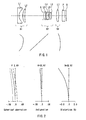
FIG. 1 is a layout drawing showing the configuration of a zoom
lens according to a first embodiment of the present invention.
-
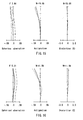
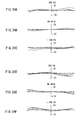
FIG. 2 shows aberration graphs for the wide-angle end of the
zoom lens according to the first embodiment of the present invention.
-
FIG. 3 shows aberration graphs for the intermediate position of
the zoom lens according to the first embodiment of the present invention.
-
FIG. 4 shows aberration graphs for the tele end of the zoom lens
according to the first embodiment of the present invention.
-
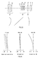
FIG. 5 is a layout drawing showing the configuration of a zoom
lens according to a second embodiment of the present invention.
-
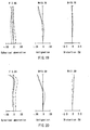
FIG. 6 shows aberration graphs for the wide-angle end of the
zoom lens according to the second embodiment of the present invention.
-
FIG. 7 shows aberration graphs for the intermediate position of
the zoom lens according to the second embodiment of the present
invention.
-
FIG. 8 shows aberration graphs for the tele end of the zoom lens
according to the second embodiment of the present invention.
-
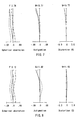
FIG. 9 is a layout drawing showing the configuration of a zoom
lens according to a third embodiment of the present invention.
-
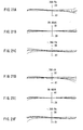
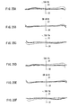
FIG. 10 shows aberration graphs for the wide-angle end of the
zoom lens according to the third embodiment of the present invention.
-
FIG. 11 shows aberration graphs for the intermediate position of
the zoom lens according to the third embodiment of the present
invention.
-
FIG. 12 shows aberration graphs for the tele end of the zoom lens
according to the third embodiment of the present invention.
-
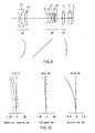
FIG. 13 is a layout drawing showing the configuration of a zoom
lens according to a fourth embodiment of the present invention.
-
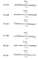
FIG. 14 shows aberration graphs for the wide-angle end of the
zoom lens according to the fourth embodiment of the present invention.
-
FIG. 15 shows aberration graphs for the intermediate position of
the zoom lens according to the fourth embodiment of the present
invention.
-
FIG. 16 shows aberration graphs for the tele end of the zoom lens
according to the fourth embodiment of the present invention.
-
FIG. 17 is a layout drawing showing the configuration of a zoom
lens according to a fifth embodiment of the present invention.
-
FIG. 18 shows aberration graphs for the wide-angle end of the
zoom lens according to the fifth embodiment of the present invention.
-
FIG. 19 shows aberration graphs for the intermediate position of
the zoom lens according to the fifth embodiment of the present invention.
-
FIG. 20 shows aberration graphs for the tele end of the zoom lens
according to the fifth embodiment of the present invention.
-
FIG. 21 shows aberration graphs for the standard state and
aberration graphs for the camera shake corrected state at the tele end,
when the aperture stop is open and the object distance is ∞, of the zoom
lens according to the sixth embodiment of the present invention.
-
FIG. 22 shows aberration graphs for the standard state and
aberration graphs for the camera shake corrected state at the tele end,
when the aperture stop is open and the object distance is ∞, of the zoom
lens according to the seventh embodiment of the present invention.
-
FIG. 23 shows aberration graphs for the standard state and
aberration graphs for the camera shake corrected state at the tele end,
when the aperture stop is open and the object distance is ∞, of the zoom
lens according to the eighth embodiment of the present invention.
-
FIG. 24 shows aberration graphs for the standard state and
aberration graphs for the camera shake corrected state at the tele end,
when the aperture stop is open and the object distance is ∞, of the zoom
lens according to the ninth embodiment of the present invention.
-
FIG. 25 shows aberration graphs for the standard state and
aberration graphs for the camera shake corrected state at the tele end,
when the aperture stop is open and the object distance is ∞, of the zoom
lens according to the tenth embodiment of the present invention.
-
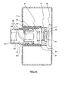
FIG. 26 diagrammatically shows the configuration of an
electronic still camera according to an eleventh embodiment of the
present invention.
-
FIG. 27 diagrammatically shows the main elements of an
electronic still camera according to a twelfth embodiment of the present
invention.
-
FIG. 28 diagrammatically shows the configuration of an
electronic still camera according to a thirteenth embodiment of the
present invention.
Best Mode for Carrying Out the Invention
-
Hereinafter, the present invention is described in further detail
using embodiments.
First Embodiment
-
FIG. 1 is a layout drawing showing the configuration of a zoom
lens according to a first embodiment of the present invention. This
zoom lens is configured so that the resolution is high and the optical
total length when collapsed is short.
-
As shown in FIG. 1, the zoom lens of this embodiment is made of
a first lens group G1 having a negative power, a second lens group G2
having a positive power, and a third lens group G3 having a positive
power, arranged in that order from the object side (left side in FIG. 1) to
the image plane S side (right side in FIG. 1), and includes seven lenses.
An aperture stop A is fixed on the object side of the second lens group G2,
and moves in the direction of the optical axis together with the second
lens group G2. Here, when zooming from the wide-angle end to the tele
end at an object distance of ∞, the first lens group G1 retreats to the
image plane S side and then moves toward the object side, the second
lens group G2 moves monotonically toward the object side, and the third
lens group G3 retreats to the image plane S side and then moves toward
the object side. Moving the third lens group G3 in the direction of the
optical axis carries out focus adjustment.
-
The first lens group G1 is made of a first lens L1 that is a
negative meniscus lens whose surface with strong curvature is facing the
image plane S side, and a second lens L2 that is a positive meniscus lens
(positive lens) whose surface with strong curvature is facing the object
side, arranged in that order from the object side.
-
The second lens group G2 is made of a third lens L3 that is a
positive lens whose convex surface (surface with strong curvature) is
facing the object side, a fourth lens L4 that is a positive lens, a fifth lens
L5 that is a negative lens, and a sixth lens L6 that is a plano-convex lens
(positive lens) whose convex surface is facing the image plane S side,
arranged in that order from the object side.
-
The third lens group G3 is made of a seventh lens L7 that is one
positive lens.
-
The fourth lens L4 and the fifth lens L5 are cemented, and the
fifth lens L5 and the sixth lens L6 are in contact with one another
outside their effective diameters. The surface on the image plane S side
of the first lens L1 and the surface on the object side of the third lens L3
are both aspherical surfaces whose local radius of curvature
monotonically increases as distance from the center increases, and the
surface on the image plane S side of the seventh lens L7 is an aspherical
surface.
-
The local radius of curvature p at the height h of the aspherical
surface from the optical axis is found as shown in
Expression 1 below.
-
In Expression 1 above, z denotes the sag amount at a height h on
the aspherical surface from the optical axis.
-
On the image plane S side of the zoom lens, an infrared cut filter,
an optical low-pass filter constituted by three quartz plates, and a
solid-state imaging element are arranged in that order from the object
side, and a cover glass for protection is attached to the solid-state
imaging element. In FIG. 1, the infrared cut filter, the optical low-pass
filter, and the cover glass are expressed as one equivalent parallel plate
element P. The image of the object captured by the zoom lens is formed
on the imaging surface (image plane S) of the solid-state imaging
element.
-
Giving the zoom lens shown in FIG. 1 a collapsing structure in
which the first lens group G1, the second lens group G2, and the third
lens group G3 are drawn toward the solid-state imaging element side
when not in use allows the optical total length when collapsed to be
shortened. A collapsing structure can be achieved by extending the cam
grooves of the cylindrical cams for moving the first lens group G1 and
the second lens group G2 in the direction of the optical axis.
-
The basic principle behind the basic configuration of the zoom
lens of the present invention is described below.
-
The zoom lens of the present invention is a zoom lens constituted
by three lens groups in which a lens group with a positive power is added
to the image plane side of a zoom lens constituted by two lens groups
with a negative, positive power arrangement in that order from the
object side that serves as a base.
-
The zooming of this zoom lens is carried out by changing the air
space between the first lens group G1 and the second lens group G2 and
also moving the third lens group G3 in the direction of the optical axis.
Also, moving the third lens group G3 in the direction of the optical axis
carries out focus adjustment. The third lens group G3 is the lightest of
the three lens groups, and thus it is suited as the lens group for focus
adjustment of autofocus, for which a high movement speed is desirable.
Also, since the third lens group G3 also acts to improve the telecentricity,
it is favorable to use a solid-state imaging element in which miniature
positive lenses are provided for each pixel.
-
To shorten the optical total length of a zoom lens constituted by
three lens groups when not in use, the overall length of the three lens
groups can be reduced. Thus, as will be discussed later, the three lens
groups are each made of a reduced number of lenses and the overall
length of each lens group is made as short as possible.
-
In compact type electronic still cameras, it is desirable that the
optical total length when not in use is shortened and that the outer
diameter of the lens barrel of the zoom lens is reduced. Since the upper
limit of the rotational angle of the cylindrical cams is for example 120° or
less, the slant angle of the cam grooves increases when the diameter of
the cylindrical cams is reduced, making it difficult to smoothly move the
first lens group G1 and the second lens group G2. Also, since the lens
barrel is made of one stationary lens barrel and one or more moving lens
barrels, to shorten the optical total length when collapsed it is necessary
to shorten the stationary lens barrel and the moving lens barrel(s).
However, if the ratio of the maximum value of the optical total length
when in use to the maximum value of the optical total length when
collapsed is large, then the first lens group G1 and the second lens group
G2 easily become decentered, deteriorating the image-forming properties
of the lens system as a whole. To solve these problems, the maximum
value of the optical total length when in use can be made small.
-
Accordingly, the zoom lens of this embodiment is configured such
that the difference between the optical total length at the wide-angle end
and the optical total length at the tele end is reduced to make the
maximum value of the optical total length when in use small. Also, the
zoom lens of this embodiment has been configured in such a way that the
combined focal length of the second lens group G2 and the combined
focal length of the third lens group G3 are set appropriately and the focal
length of the third lens L3 and the focal length of the sixth lens L6 are
set appropriately to achieve good image-forming properties and a short
optical total length when in use. Moreover, the zoom lens of this
embodiment is configured in such a manner that when zooming from the
wide-angle end to the tele end with an object distance of ∞, the third lens
group G3 retreats to the image plane S side and then moves toward the
object side, reducing the maximum value of the optical total length when
in use.
-
The optical total length when in use of a zoom lens constituted by
two lens groups of negative and positive power arranged in that order
from the object side is longest at the wide-angle end and the tele end and
shortest at zoom positions therebetween. Also, when a third lens group
that has a positive power is arranged in a fixed location on the image
plane side of the zoom lens constituted by two lens groups, the optical
total length when in use is still longest at the wide-angle end and the
tele end and shortest at zoom positions therebetween. From this it can
be understood that when the third lens group G3 is separated from the
image plane S the optical total length becomes shorter at the wide-angle
end and the tele end. To increase this effect, the magnification of the
third lens group G3 can be increased, and to do that the combined focal
length of the third lens group G3 can be shortened and the third lens
group G3 be separated from the image plane S. Since it is not necessary
to forcibly shorten the optical total length between the wide-angle end
and the tele end, the third lens group G3 can be brought closer to the
image plane S in order to reduce the spherical aberration that is
generated at the third lens group G3. Taking the above matters into
consideration, the zoom lens of this embodiment is configured such that
the third lens group G3 retreats to the image plane S side and then
moves toward the object side when zooming from the wide-angle end to
the tele end at an object distance of ∞.
-
In the zoom lens of this embodiment, the following measures have
been taken into order to shorten the total length of each lens group.
-
In order to shorten its overall length, the first lens group G1 has
been made of two lenses, a negative lens and a positive lens, arranged in
that order from the object side. The first lens L1 is a negative lens
(negative meniscus lens) that generates negative distortion, and the
positive second lens L2 generates positive distortion in order to reduce
the negative distortion at the wide-angle end of the overall lens system.
Also, to further reduce this distortion, the image plane S side surface of
the first lens L1 is an aspherical surface whose local radius of curvature
increases monotonically as distance from the center increases.
-
The second lens group G2 is made of four lenses, which are a
positive lens, a positive lens, a negative lens, and a positive lens,
arranged in that order from the object side. Also, here, the positive lens
with the strong positive power is arranged furthest on the object side
and the positive lens with the weak positive power is arranged furthest
on the image plane S side, so that the principal point of the object side of
the second lens group G2 is deviated toward the object side. Thus, at
the tele end where the first lens group G1 and the second lens group G2
are nearest one another, the distance from the principal point on the
image plane S side of the first lens group G1 to the principal point on the
object side of the second lens group G2 can be shortened, allowing the
combined focal length of the second lens group G2 to be shortened, and
thus the optical total length during use is shortened. Also, with the
configuration of the zoom lens of this embodiment, the fourth lens L4
and the fifth lens L5 are cemented and the fifth lens L5 and the sixth
lens L6 are in contact with one another outside their effective diameters,
thereby shortening the overall length of the second lens group G2.
-
In the zoom lens of this embodiment, the aperture stop A is
disposed near the object side of the third lens L3, and thus the incidence
height of axial light is largest at the third lens L3, and if both surfaces of
the third lens L3 are spherical, then a negative spherical aberration
occurs at the third lens L3. Accordingly, by making the object side
surface of the third lens L3 an aspherical surface in which the local
radius of curvature increases monotonically with increased distance from
the center, a reduction in the spherical aberration that occurs at the
third lens group G3 is achieved.
-
The third lens group G3 is constituted by a seventh lens L7 that
is one positive lens and thus it has a short overall length. The image
plane S side surface of the seventh lens L7 is an aspherical surface,
which generates positive distortion, reducing the absolute value of the
negative distortion at the wide-angle end.
-
Focus adjustment is carried out by fixing the first lens group G1
and the second lens group G2 and moving only the third lens group G3 in
the direction of the optical axis. Here, the third lens group G3 moves
toward the object side as the object distance shortens. The third lens
group G3 is made of one lens, and the moving portion, which includes
other mechanical components that move, is lightweight, so that the third
lens group G3 can be moved at high speeds using a low-power compact
motor, and thus autofocus adjustment can be carried out quickly. It
should be noted that the lateral chromatic aberration changes when the
seventh lens L7 is moved for focus adjustment, but this is inhibited
enough that in practice it is not a problem.
-
The zoom lens of this embodiment is configured such that the
following conditional expressions are satisfied.
|LW - LT| / LW < 0.1
1.9 < fG2 / fW < 2.4
3.2 < fG3 / fW < 4.0
0.6 < f3 / fG2 < 1.1
1.5 < f6 / fG2 < 1.8
n3 > 1.75
ν3 > 35
n4 > 1.6
ν4 > 45
n6 > 1.7
35 < ν6 < 50
-
Here, LW is the optical total length (length from the apex of the
object side surface of the first lens L1 to the image plane) at the
wide-angle end, LT is the optical total length at the tele end, fG2 is the
combined focal length of the second lens group G2, fG3 is the combined
focal length of the third lens group G3, fW is the combined focal length of
the overall lens system at the wide-angle end at an object distance of ∞,
fi is the focal length of the i-th (i is a natural number) lens, ni is the
refractive index of the i-th lens, and νi is the Abbe number of the i-th
lens.
-
In the zoom lens of this embodiment, it is desirable that the
following conditional expression is satisfied.
-0.8 < κ3F + 8D3Fr3F3 < -0.5.
-
Here, κ3F is the conic constant of the object side surface of the
third lens L3, D3F is the fourth-order aspheric coefficient of the object
side surface of the third lens L3, and r3F is the paraxial radius of
curvature of the object side surface of the third lens L3.
-
The above conditional expressions are described below.
-
The Conditional Expression (1) is a conditional expression for
reducing the maximum value of the optical total length when in use and
for ensuring good image-forming properties. To reduce the maximum
value of the optical total length when in use, ideally the optical total
length at the wide-angle end and the optical total length at the tele end
are made equal. However, when the optical total length at the
wide-angle end and the optical total length at the tele end are made
completely equal, the image-forming properties may be sacrificed. The
above Conditional Expression (1) was arrived at in light of these matters.
If the Conditional Expression (1) is not satisfied, then it is difficult to
shorten the optical total length when in use and ensure good
image-forming properties.
-
The Conditional Expression (2) is a conditional expression for
shortening the optical total length when in use as much as possible and
simultaneously correcting with good balance the generation of various
aberrations. When fG2 / fW is 2.4 or more, then the conjugate distance of
the second lens group G2 (the distance from the object point to the image
point) is increased, and this increases the optical total length when in
use. In this case, the optical total length is shortened if the
magnification of the third lens group G3 is reduced, but because the
power of the third lens group G3 becomes large, the curvature of field
that is generated by the third lens group G3 is not sufficiently corrected,
and it becomes difficult to correct this curvature of field with the first
lens group G1 and the second lens group G2. On the other hand, when
fG2/ fW is 1.9 or less, the optical total length when in use is short but it is
difficult to secure enough air distance at the tele end to dispose the
aperture stop A between the first lens group G1 and the second lens
group G2.
-
The Conditional Expression (3) is a conditional expression for
making the slant angle of the principal ray at the maximum image
height that it is incident on the solid-state imaging element small, that
is, making the telecentricity good, and reducing the curvature of field.
When fG3 / fW is 3.2 or less, there is good telecentricity but the curvature
of field of the overall lens system cannot be corrected. On the other
hand, when fG3 / fW is 4.0 or more, the curvature of field is reduced but
the telecentricity is insufficient.
-
The Conditional Expressions (4) and (5) are conditional
expressions for correcting with good balance the aberrations generated
at the second lens group G2 and for shortening the optical total length of
the overall lens system when in use. If f3 / fG2 is 1.1 or more, or if f6 / fG2
is 1.5 or less, then deviation of the principal point on the object side of
the second lens group G2 toward the object side is insufficient, and thus
when setting the length from the image plane S side principal point of
the first lens group G1 to the object side principal point of the second
lens group G2 at the tele end to a desired length, it becomes difficult to
ensure enough air space to dispose the aperture stop A between the first
lens group G1 and the second lens group G2. On the other hand, if f3 /fG2
is 0.6 or less, or if f6 / fG2 is 1.8 or more, then there is sufficient
deviation of the object side principal point of the second lens group G2
toward the object side, sufficient air distance can be secured at the tele
end to dispose the aperture stop A between the first lens group G1 and
the second lens group G2, and the optical total length when in use can be
shortened, but the power of the fourth lens L4 becomes too great, and
this makes it difficult to correct with good balance the spherical
aberration and the coma that are generated at the fourth lens L4 using
other lenses.
-
The Conditional Expressions (6) to (11) are conditional
expressions for reducing longitudinal chromatic aberration and lateral
chromatic aberration when zooming from the wide-angle end to the tele
end, and for reducing the curvature of field. If any one of Conditional
Expressions (6) to (11) is not satisfied, then problems that may occur
include noticeable color blurring at either zoom position due to an
increase in the longitudinal chromatic aberration or the lateral
chromatic aberration, and the image-forming properties may become
worse at some parts of the captured image due to the curvature of field
not becoming small.
-
The Conditional Expression (12) is a conditional expression for
regulating the conic constant and the fourth-order aspheric coefficient
for the aspherical surface on the object side of the third lens L3 so as to
reduce the sensitivity to decentration of the object side surface of the
third lens L3 with respect to light rays having a small field angle that
pass through the center portion of the aperture stop A. κ3F + 8D3Fr3F 3
expresses the extent of deviation of the aspherical surface from a
spherical surface. When κ3F + 8D3Fr3F 3 is -0.8 or less, the effects of the
aspherical surface reduce the spherical aberration that is generated by
the object side surface of the third lens L3, but the decentering coma and
the decentering astigmatism that are generated by the object side
surface of the third lens L3 become too great, and this increases the
sensitivity to decentration of the object side surface of the third lens L3.
On the other hand, when κ3F + 8D3Fr3F 3 is -0.5 or more, the decentering
coma and the decentering astigmatism that are generated by the object
side surface of the third lens L3 become small, but the spherical
aberration is not sufficiently corrected or the radius of curvature of the
image-plane side surface of the fifth lens L5 becomes short, and thus the
decentering coma and the decentering astigmatism that are generated by
the image-plane side surface of the fifth lens L5 become large, which
increases the sensitivity to decentration of the image-plane side surface
of the fifth lens L5.
-
Table 1 below shows specific examples of the numerical values
(lens data) of the zoom lens shown in FIG. 1.
| Group | Element | Surface | R | d | nd | νd |
| G1 | L1 | 1 | 220.428 | 1.500 | 1.75016 | 45.1 |
| | 2 | 5.890* | 2.999 |
| L2 | 3 | 12.359 | 1.630 | 1.84666 | 23.9 |
| | 4 | 31.007 | variable |
| G2 | Stop | 5 | ∞ | 0.900 |
| L3 | 6 | 6.430* | 1.680 | 1.80431 | 40.9 |
| | 7 | 130.545 | 0.237 |
| L4 | 8 | 10.586 | 1.700 | 1.62299 | 58.1 |
| L5 | 9 | -96.073 | 0.700 | 1.84666 | 23.8 |
| | 10 | 4.534 | 0.688 |
| L6 | 11 | 49.920 | 1.200 | 1.80610 | 40.7 |
| | 12 | -23.629 | variable |
| G3 | L7 |
| | 13 | 14.222 | 1.900 | 1.51459 | 62.6 |
| | 14 | -38.157* | variable |
| P |
| | 15 | ∞ | 2.300 | 1.51680 | 64.2 |
| 16 | ∞ |
-
The unit of length in the table is [mm]. In Table 1 above, r is the
radius of curvature of the lens, d is the distance between surfaces, and nd
and νd are the refractive index and the Abbe number of the lens at the
d-line, respectively (the same applies for other embodiments described
later). It should be noted that surfaces with an * mark are aspheric and
that their aspheric shape is defined by Expression 2 shown below (the
same applies for other embodiments described later).
Expression 2 z = h2/r 1 + 1 - (1 + κ)(h/r)2 + Dh4 + Eh6 + Fh8 + Gh10
-
In Expression 2 shown above, h is the height from the optical axis,
z is the sag amount at the point on the aspherical surface where the
height from the optical axis is h, κ is the conic constant, and D, E, F and
G are the fourth-order, sixth-order, eighth-order and tenth-order
aspheric coefficients, respectively.
-
Table 2 below shows the conic constant and the aspheric
coefficients (aspheric data) of the zoom lens shown in FIG. 1.
| | Second Surface | Sixth Surface | Fourteenth Surface |
| κ | -0.796896 | -0.144654 | 0.0 |
| D | 1.25832×10⁻⁶ | -2.20926×10⁻⁴ | 1.69331×10⁻⁴ |
| E | 1.19237×10⁻⁶ | -4.46557×10⁻⁶ | -1.68788×10⁻⁵ |
| F | -5.76048×10⁻⁸ | 1.48953×10⁻⁷ | 6.28843×10⁻⁷ |
| G | 1.06614×10⁻⁹ | -1.17063×10⁻⁸ | -8.52576×10⁻⁹ |
-
Table 3 below shows the variable distance between surfaces (in
mm) (variable surface spacing data) when the object distance of the zoom
lens shown in FIG. 1 is ∞. In Table 3, f (mm) and 2ω represent the
focal length and the field angle, respectively (the same applies for other
embodiments described later).
| Surface Spacing | Wide-angle End | Intermediate Position | Tele End |
| d4 | 14.738 | 6.884 | 1.300 |
| d12 | 3.992 | 10.664 | 18.939 |
| d14 | 2.812 | 1.508 | 1.304 |
| f | 5.815 | 10.067 | 17.416 |
| F value | 2.80 | 3.77 | 5.21 |
| 2ω | 65.7° | 39.6° | 23.2° |
| L | 40.066 | 37.580 | 40.066 |
-
Here, when fW is the combined focal length of the entire lens
system at the wide-angle end and fT is the combined focal length of the
entire lens system at the tele end when the object distance is ∞, then the
zoom position at which the focal length is
fN=(fW fT)1/2
is called the "intermediate position."
-
FIGs. 2, 3 and 4 are aberration graphs (spherical aberration,
astigmatism and distortion) of the zoom lens shown in FIG. 1 when the
aperture stop is open and the object distance is ∞. FIG. 2 is the case for
the wide-angle end, FIG. 3 is the case for the intermediate position, and
FIG. 4 is the case for the tele end. It should be noted that in the
spherical aberration diagrams, the solid line indicates characteristics at
the d-line, the short dashed line indicates characteristics at the F-line,
and the long dashed line indicates characteristics at the C-line. Also, in
the astigmatism diagrams, the solid line indicates the sagittal curvature
of field and the dashed line indicates the meridional curvature of field
(the same applies for other embodiments described later).
-
It is clear from the aberration graphs shown in FIGs. 2 to 4 that
the zoom lens of this embodiment demonstrates good aberration
properties even if the zoom position is changed.
-
If the zoom lens shown in FIG. 1 is packaged in an electronic still
camera, then as the solid-state imaging element it is possible to use an
element whose recording pixel number is 2048 (horizontal) × 1536
(vertical) (approximately 3 million pixels), whose pixel pitch is 2.8 µm
(horizontal) × 2.8 µm (vertical), and whose recording picture size is
5.7344 mm (horizontal) × 4.3008 mm (vertical). As the solid-state
imaging element, it is also possible to use an element in which a
miniature positive lens is provided at each pixel in order to increase the
effective aperture ratio.
-
In the zoom lens shown in FIG. 1, the three lenses of the third
lens L3 to the fifth lens L5 in the second lens group G2 are highly
sensitive to decentration. Accordingly, in the zoom lens of this
embodiment, the fourth lens L4 and the fifth lens L5 are cemented and
the fifth lens L5 and the sixth lens L6 are in contact with one another
outside their effective diameters. Additionally, the surface of the third
lens L3 on the image plane side is a concave surface so that the third
lens L3 can be centered easily during assembly.
-
When the fourth lens L4 and the fifth lens L5 are cemented, the
refractive index difference at the border of the two surfaces of the
adhesive agent is reduced, thus lowering the sensitivity to decentration
of the image plane side surface of the fourth lens L4 and the object side
surface of the fifth lens L5. Also, when the fifth lens L5 and the sixth
lens L6 are in contact with one another outside their effective diameters,
the decentration between the image plane side surface of the fifth lens
L5 and the object side surface of the sixth lens L6 is reduced. Also,
since the lenses are cemented and in contact with one another, the need
for spacers, which easily lead to the occurrence of error in the surface
spacing, is eliminated. Thus compared to a case in which spacers are
used, error in the surface spacing can be reduced.
-
To carry out lens alignment, the following can be performed.
That is, first, the fourth lens L4 and the fifth lens L5 are cemented and
together with the sixth lens L6 are incorporated into the lens frame,
after which the third lens L3 is attached to a predetermined position and
an decentration measuring device is used to adjust the position of the
third lens L3 so that the state of decentration of the entire second lens
group G2 is small. Lastly, the third lens L3 is fixed to the lens frame
using an adhesive agent. At this time, if the image plane side surface of
the third lens L3 is a convex surface, then when the third lens L3 is
moved, both parallel decentration (decenter) and tilt decentration (tilt)
occur, making lens alignment difficult. On the other hand, in the zoom
lens shown in FIG. 1, the image plane side surface of the third lens L3 is
the concave surface, and thus the third lens L3 can be parallel displaced
without being tilted, making lens alignment easy. It should be noted
that the image plane side surface of the third lens L3 can also be a flat
surface, and in this case as well, lens alignment is easy.
-
As described above, the zoom lens shown in FIG. 1 has a zoom
ratio of approximately ×3.0 at an object distance of ∞, a field angle at the
wide-angle end of approximately 66° , high resolution, and a short
optical total length when not in use.
Second Embodiment
-
FIG. 5 is a layout drawing showing the configuration of a zoom
lens according to a second embodiment of the present invention. This
zoom lens is configured such that the resolution is high, the optical total
length when collapsed is short, and the sensitivity to decentration is
lower than in the zoom lens according to the first embodiment.
-
As shown in FIG. 5, the zoom lens of this embodiment is made of
a first lens group G1 having a negative power, a second lens group G2
having a positive power, and a third lens group G3 having a positive
power, arranged in that order from the object side (left side in FIG. 5) to
the image plane S side (right side in FIG. 5), and includes seven lenses.
An aperture stop A is fixed on the object side of the second lens group G2,
and moves in the direction of the optical axis together with the second
lens group G2.
-
The zoom lens shown in FIG. 5 has the same configuration as the
zoom lens shown in the first embodiment, and is different only in the
material of some of the lenses. That is, in the zoom lens shown in this
embodiment, the fourth lens L4, the sixth lens L6 and the seventh lens
L7 are set to have higher refractive indices than in the zoom lens
described in the first embodiment.
-
If the lens surfaces of the lenses making up the zoom lens are
decentered, then there is the problem that the image-forming properties
drop in some regions on the imaging surface of the solid-state imaging
element. Many of the lens surfaces of the lenses making up the second
lens group G2 are highly sensitive to decentration, and in particular, the
object side surface of the third lens L3 and the image plane S side
surface of the fifth lens L5 easily become very sensitive to decentration.
-
In response to this problem, the inventors of the present
application independently evaluated third-order aberration when the
lens surfaces of the lenses of the zoom lens were decentered, and
moreover performed an analysis of the third-order decentering coma and
the third-order decentering astigmatism. The results showed that to
lower the sensitivity to decentration of the lens surfaces of the lenses of
the zoom lens, the ratio of the decentering coma that occurs at the lens
surfaces to the amount of decentration of those lens surfaces (the surface
coefficient of the decentering coma), and the ratio of the decentering
astigmatism that occurs at the lens surfaces to the amount of
decentration of those lens surfaces (the surface coefficient of the
decentering astigmatism) can be reduced. It was also found that it may
be possible to improve the image-forming properties on the imaging
surface (image plane S) of the solid-state imaging element by suitably
tilting the solid-state imaging element if the surface coefficients of the
decentering coma and the decentering astigmatism that occur at the lens
surfaces are both small and the amount of decentration of the lens
surfaces is small.
-
Using the results of the above analysis, it was found that to lower
the sensitivity to decentration of the object side surface of the third lens
L3 and the image plane side surface of the fifth lens L5, it is possible to
reduce the incidence angle if the axial light that passes through the edge
of the aperture stop A is incident on the lens surface through air or the
refraction angle in air if that axial light is emitted from the lens surface
into the air. Accordingly, in this embodiment, the refractive index of the
fourth lens L4 is increased, and thus the radius of curvature of the object
side surface of the third lens L3 is made larger. Also, the refractive
index of the sixth lens L6 and the refractive index of the seventh lens L7
are increased so that leeway is given to the Petzval sum, and utilizing
this leeway, the radius of curvature of the image plane side surface of the
fifth lens L5 is made large.
-
The result of performing the above is that the sensitivity to
decentration of the object side surface of the third lens L3 and of the
image plane side surface of the fifth lens L5 of the zoom lens shown in
FIG. 5 is lower than the sensitivity to decentration of those lens surfaces
of the zoom lens shown in FIG. 1.
-
In the zoom lens shown in FIG. 5, if the lens surfaces have only
minute decentration, then by tilting the solid-state imaging element the
image-forming properties on the imaging surface of the solid-state
imaging element can be favorably corrected. However, if the amount of
decentration of the lens surfaces is large or if the decentration of the lens
surfaces leads to an increase in the decentering coma and the
decentering astigmatism of the overall lens system, then the
image-forming properties remain poor at some regions of the imaging
surface of the sold-state imaging element, and thus there is a limit to
this method of tilting the solid-state imaging element.
-
In the zoom lens of this embodiment, like the zoom lens according
to the first embodiment, the optical total length when collapsed and the
optical total length when in use can both be shortened.
-
The zoom lens of this embodiment is configured such that the
following conditional expressions are satisfied.
|LW - LT| / LW < 0.1
1.9 < fG2 / fW < 2.4
3.2 < fG3 / fW < 4.0
0.6 < f3 / fG2 < 1.1
1.5 < f6 / fG2 < 1.8
n3 > 1.75
ν3 > 35
n4 > 1.7
ν4 > 45
n6 > 1.7
35 < ν6 < 50
-
In the zoom lens of this embodiment, it is also desirable that the
following conditional expression is satisfied.
-0.8 < κ3F + 8D3Fr3F3 < -0.5.
-
Here, LW is the optical total length (length from the apex of the
object side surface of the first lens L1 to the image plane) at the
wide-angle end, LT is the optical total length at the tele end, fG2 is the
combined focal length of the second lens group G2, fG3 is the combined
focal length of the third lens group G3, fW is the combined focal length of
the overall lens system at the wide-angle end at an object distance of ∞,
fi is the focal length of the i-th (i is a natural number) lens, ni is the
refractive index of the i-th lens, νi is the Abbe number of the i-th lens, r3F
is the paraxial radius of curvature of the object side surface of the third
lens L3, κ3F is the conic constant of the object side surface of the third
lens L3, and D3F is the fourth-order aspheric coefficient of the object side
surface of the third lens L3.
-
The above conditional expressions are described below.
-
The above Conditional Expressions (1) to (7) and (9) to (12) are
that same as those described above in the first embodiment. It should
be noted that the lower limit of the Conditional Expression (8') is larger
than the lower limit of the Conditional Expression (8) described above in
the first embodiment. This is in order to reduce the longitudinal
chromatic aberration and the lateral chromatic aberration when zooming
from the wide-angle end to the tele end and also to reduce the curvature
of field and simultaneously to effectively obtain the effect of reducing the
sensitivity to decentration of the object side surface of the fourth lens L4.
-
Table 4 below shows specific examples of the numerical values of
the zoom lens shown in FIG. 5.
| Group | Element | Surface | r | d | nd | νd |
| | L1 | 1 | 225.905 | 1.500 | 1.75016 | 45.1 |
| G1 | | 2 | 5.766* | 2.663 |
| | L2 | 3 | 11.648 | 1.630 | 1.84666 | 23.8 |
| | | 4 | 30.495 | variable |
| G2 | Stop | 5 | ∞ | 0.900 |
| L3 | 6 | 7.161* | 1.680 | 1.80431 | 40.9 |
| | 7 | 126.608 | 0.489 |
| L4 | 8 | 11.950 | 1.870 | 1.74330 | 49.2 |
| L5 | 9 | -27.949 | 0.700 | 1.84666 | 23.8 |
| | 10 | 5.026 | 0.629 |
| L6 | 11 | 84.504 | 1.200 | 1.83400 | 37.3 |
| | 12 | -20.572 | variable |
| G3 | L7 |
| | 13 | 16.576* | 1.900 | 1.66556 | 54.8 |
| | | 14 | -67.979 | variable |
| P |
| | 15 | ∞ | 2.300 | 1.51680 | 64.2 |
| 16 | ∞ |
-
Table 5 below shows the conic constant and the aspheric
coefficients of the zoom lens shown in FIG. 5.
| | Second Surface | Sixth Surface | Thirteenth Surface |
| κ | -0.817589 | -0.103669 | 0.0 |
| D | 3.43794×10⁻⁵ | -1.80096×10⁻⁴ | -8.69685×10⁻⁵ |
| E | 3.12408×10⁻⁷ | -9.49587×10⁻⁶ | 7.80173×10⁻⁶ |
| F | -1.38434×10⁻⁸ | 1.06823×10⁻⁶ | -2.22915×10⁻⁷ |
| G | 3.13288×10⁻¹⁰ | -5.88664×10⁻⁸ | 1.51594×10⁻⁹ |
-
Also, Table 6 below shows the variable distance between surfaces
(in mm) when the object distance of the zoom lens shown in FIG. 5 is ∞.
| Surface Spacing | Wide-angle End | Intermediate Position | Tele End |
| d4 | 14.832 | 6.799 | 1.097 |
| d12 | 4.051 | 10.600 | 18.856 |
| d14 | 2.890 | 1.750 | 1.820 |
| f | 5.817 | 10.072 | 17.423 |
| F value | 2.80 | 3.74 | 5.12 |
| 2ω | 65.7° | 39.5° | 23.2° |
| L | 40.324 | 37.700 | 40.324 |
-
FIGs. 6 to 8 are aberration graphs (spherical aberration,
astigmatism, and distortion) of the zoom lens shown in FIG. 5 when the
object distance is ∞ and the aperture stop is fully open. FIG. 6 shows
the case for the wide-angle end, FIG. 7 shows the case for the
intermediate position, and FIG. 8 shows the case for the tele end.
-
It is clear from the aberration graphs shown in FIGs. 6 to 8 that
the zoom lens of this embodiment demonstrates good aberration
properties even if the zoom position is changed.
-
If the zoom lens shown in FIG. 5 is packaged in an electronic still
camera, then the same solid-state imaging element described in the first
embodiment can be used.
-
Since the image plane side surface of the third lens L3 is a
concave surface, if necessary, the third lens L3 can be aligned easily
during assembly, as described in the first embodiment. Also, if the
image-forming properties are not good at some regions on the imaging
surface (image plane S) of the solid-state imaging element, then the
solid-state imaging element can be tilted by 1° or less to improve the
image-forming properties on the imaging surface (image plane S) of the
solid-state imaging element.
-
As described above, the zoom lens shown in FIG. 5 has a zoom
ratio of approximately ×3.0 at an object distance of ∞, a field angle at the
wide-angle end of approximately 66° , high resolution, a short optical
total length when not in use, and low sensitivity to decentration.
Third Embodiment
-
FIG. 9 is a layout drawing showing the configuration of a zoom
lens according to a third embodiment of the present invention. This
zoom lens is configured such that the resolution is high, the optical total
length when collapsed is short, and the sensitivity to decentration is low.
-
As shown in FIG. 9, the zoom lens of this embodiment is made of
a first lens group G1 having a negative power, a second lens group G2
having a positive power, and a third lens group G3 having a positive
power, arranged in that order from the object side (left side in FIG. 9) to
the image plane S side (right side in FIG. 9), and includes seven lenses.
An aperture stop A is fixed on the object side of the second lens group G2,
and moves in the direction of the optical axis together with the second
lens group G2.
-
The zoom lens shown in FIG. 9 has the same configuration as the
zoom lens shown in the second embodiment, and is different only in the
material of some of the lenses. That is, in the zoom lens shown in this
embodiment, the fourth lens L4 is set to have a higher refractive index
than in the zoom lens described in the second embodiment.
-
In order to obtain better optical properties, the zoom lens of this
embodiment also is configured such that the conditional expressions (1)
to (7), (8'), and (9) to (12) described above in the second embodiment are
satisfied.
-
Table 7 below shows specific examples of the numerical values of
the zoom lens shown in FIG. 9.
| Group | Element | Surface | r | d | nd | νd |
| | L1 | 1 | 206.431 | 1.500 | 1.75016 | 45.1 |
| G1 | | 2 | 5.701* | 2.641 |
| | L2 | 3 | 11.480 | 1.730 | 1.84666 | 23.8 |
| | | 4 | 29.922 | variable |
| G2 | Stop | 5 | ∞ | 0.900 |
| L3 | 6 | 7.625* | 1.680 | 1.80431 | 40.9 |
| | 7 | 97.314 | 0.954 |
| L4 | 8 | 11.929 | 1.400 | 1.77250 | 49.6 |
| L5 | 9 | -35.487 | 0.700 | 1.84666 | 23.8 |
| | 10 | 5.473 | 0.657 |
| L6 | 11 | ∞ | 1.200 | 1.83400 | 37.3 |
| | 12 | -17.928 | variable |
| G3 | L7 |
| | 13 | 17.116* | 1.800 | 1.66556 | 54.8 |
| | | 14 | -86.399 | variable |
| P |
| | 15 | ∞ | 2.300 | 1.51680 | 64.2 |
| 16 | ∞ |
-
Table 8 below shows the conic constant and the aspheric
coefficients of the zoom lens shown in FIG. 9.
| | Second Surface | Sixth Surface | Thirteenth Surface |
| κ | -0.780185 | -0.172315 | 0.0 |
| D | 7.44081×10⁻⁶ | -1.48634×10⁻⁴ | -7.76937×10⁻⁵ |
| E | 4.90696×10⁻⁷ | -4.38984×10⁻⁶ | 8.93374×10⁻⁶ |
| F | -2.44580×10⁻⁸ | 3.50644×10⁻⁷ | -4.34486×10⁻⁷ |
| G | 3.97293×10⁻¹⁰ | -1.69741×10⁻⁸ | 8.55719×10⁻⁹ |
-
Also, Table 9 below shows the variable distance between surfaces (in mm) when the object distance of the zoom lens shown in FIG. 9 is ∞.
| Surface Spacing | Wide-angle End | Intermediate Position | Tele End |
| d4 | 16.026 | 7.298 | 1.650 |
| d12 | 4.612 | 11.097 | 20.149 |
| d14 | 3.260 | 2.397 | 2.099 |
| f | 5.816 | 10.069 | 17.425 |
| F value | 2.77 | 3.64 | 5.02 |
| 2ω | 65.7° | 39.6° | 23.2° |
| L | 42.450 | 39.344 | 42.450 |
-
FIGs. 10, 11, and 12 are aberration graphs (spherical aberration,
astigmatism, and distortion) of the zoom lens shown in FIG. 9 when the
object distance is ∞ and the aperture stop is fully open. FIG. 10 shows
the case for the wide-angle end, FIG. 11 shows the case for the
intermediate position, and FIG. 12 shows the case for the tele end.
-
It is clear from the aberration graphs shown in FIGs. 10 to 12
that the zoom lens of this embodiment demonstrates good aberration
properties even if the zoom position is changed. It should be noted that
although the distortion at the wide-angle end is slightly large, the
image-forming properties at high-frequency spatial frequencies are good
over the overall captured image.
-
If the zoom lens shown in FIG. 9 is packaged in an electronic still
camera, then the same solid-state imaging element described in the first
embodiment can be used.
-
Since the image plane side surface of the third lens L3 is a
concave surface, if necessary, the third lens L3 can be aligned easily
during assembly as described in the first embodiment. Also, if the
image-forming properties are not good at some regions on the imaging
surface (image plane S) of the solid-state imaging element, then the
solid-state imaging element can be tilted by 1° or less to improve the
image-forming properties on the imaging surface (image plane S) of the
solid-state imaging element.
-
As described above, the zoom lens shown in FIG. 9 has a zoom
ratio of approximately ×3.0 at an object distance of ∞, a field angle at the
wide-angle end of approximately 66° , high resolution, a short optical
total length when not in use, and low sensitivity to decentration.
Fourth Embodiment
-
FIG. 13 is a layout drawing showing the configuration of a zoom
lens according to a fourth embodiment of the present invention. This
zoom lens is configured such that the resolution is high, the optical total
length when collapsed is short, the sensitivity to decentration is low, and
the distortion is good.
-
As shown in FIG. 13, the zoom lens of this embodiment is made of
a first lens group G1 having a negative power, a second lens group G2
having a positive power, and a third lens group G3 having a positive
power, arranged in that order from the object side (left side in FIG. 13) to
the image plane S side (right side in FIG. 13), and includes seven lenses.
An aperture stop A is fixed on the object side of the second lens group G2,
and moves in the direction of the optical axis together with the second
lens group G2.
-
The zoom lens shown in FIG. 13 has the same configuration as
the zoom lens shown in the third embodiment, except that the lens data
are slightly different. That is, primarily, in the zoom lens shown in FIG.
13, the radius of curvature of the object side surface of the first lens L1 is
reduced so that the absolute value of the distortion at the wide-angle end
is reduced.
-
In order to obtain better optical properties, the zoom lens of this
embodiment is configured such that the conditional expressions (1) to (7),
(8'), and (9) to (12) described above in the second embodiment are
satisfied, and furthermore, that the following conditional expressions are
also satisfied
9 < r1F / fW < 13
3.8 < r2R / fW < 4.7.
-
Here, r1F is the radius of curvature of the object side surface of
the first lens L1 and r2R is the radius of curvature of the image plane S
side surface of the second lens L2.
-
Conditional Expression (13) is for reducing the negative
distortion at the wide-angle end by regulating the radius of curvature of
the object side surface of the first lens L1. If r1F / fW is 9 or less, then
the negative distortion at the wide-angle end is small but the coma and
the astigmatism become too large, making it difficult to improve the
image-forming properties of the peripheral portion of the captured image.
On the other hand, if r1F / fW is 13 or more, then it is difficult to reduce
the negative distortion at the wide-angle end with the lens surface of the
subsequent lens.
-
Conditional Expression (14) is for reducing the negative
distortion at the wide-angle end by regulating the radius of curvature of
the image plane side surface of the second lens L2 once Conditional
Expression (13) has been satisfied. If r2R / fW is 3.8 or less, then the
absolute value of the distortion at the wide-angle end is small but the
coma and the astigmatism become too large, making it difficult to
improve the image-forming properties at the peripheral portions of the
captured image. On the other hand, if r2R / fW is 4.7 or more, then it is
difficult to reduce the negative distortion at the wide-angle end with the
lens surface of the subsequent lens.
-
Table 10 below shows specific examples of the numerical values of
the zoom lens shown in FIG. 13.
| Group | Element | Surface | r | d | nd | νd |
| | L1 | 1 | 61.136 | 1.500 | 1.75016 | 45.1 |
| G1 | | 2 | 5.435* | 2.630 |
| | L2 | 3 | 10.744 | 1.730 | 1.84666 | 23.8 |
| | | 4 | 24.549 | variable |
| G2 | Stop | 5 | ∞ | 0.900 |
| L3 | 6 | 7.890* | 1.680 | 1.80431 | 40.9 |
| | 7 | 42.884 | 1.076 |
| L4 | 8 | 9.227 | 1.400 | 1.77250 | 49.6 |
| L5 | 9 | -78.853 | 0.600 | 1.84666 | 23.8 |
| | 10 | 5.313 | 0.635 |
| L6 | 11 | 76.126 | 1.200 | 1.83400 | 37.3 |
| | 12 | -23.315 | variable |
| G3 | L7 |
| | 13 | 15.967* | 1.800 | 1.66556 | 54.8 |
| | | 14 | -104.750 | variable |
| P |
| | 15 | ∞ | 2.100 | 1.51680 | 64.2 |
| 16 | ∞ |
-
Table 11 below shows the conic constant and the aspheric
coefficients of the zoom lens shown in FIG. 13.
| | Second Surface | Sixth Surface | Thirteenth Surface |
| κ | -0.742687 | -0.604891 | 0.682611 |
| D | 1.45088×10⁻⁵ | -8.66906×10⁻⁶ | -1.27919×10⁻⁴ |
| E | 1.70813×10⁻⁶ | 1.37873×10⁻⁶ | 8.92286×10⁻⁶ |
| F | -6.25193×10⁻⁸ | -8.55598×10⁻⁸ | -4.14031×10⁻⁷ |
| G | 7.91262×10⁻¹⁰ | 8.53680×10⁻¹⁰ | 7.67921×10⁻⁹ |
-
Also, Table 12 below shows the variable distance between
surfaces (in mm) when the object distance of the zoom lens shown in FIG.
13 is ∞.
| Surface Spacing | Wide-angle End | Intermediate Position | Tele End |
| d4 | 15.529 | 7.298 | 1.650 |
| d12 | 4.857 | 11.061 | 20.065 |
| d14 | 3.341 | 2.565 | 2.314 |
| f | 5.964 | 10.059 | 17.393 |
| F value | 2.80 | 3.64 | 5.01 |
| 2ω | 63.0° | 39.3° | 23.2° |
| L | 42.067 | 39.265 | 42.370 |
-
FIGs. 14, 15, and 16 are aberration graphs (spherical aberration,
astigmatism, and distortion) of the zoom lens shown in FIG. 13 when the
object distance is ∞ and the aperture stop is fully open. FIG. 14 shows
the case for the wide-angle end, FIG. 15 shows the case for the
intermediate position, and FIG. 16 shows the case for the tele end.
-
It is clear from the aberration graphs shown in FIGs. 14 to 16
that the zoom lens of this embodiment demonstrates good aberration
properties even if the zoom position is changed, and that the distortion
at the maximum image height is small, being -2.0% at the wide-angle
end and 0.7% at the tele end.
-
If the zoom lens shown in FIG. 13 is packaged in an electronic
still camera, then the same solid-state imaging element described in the
first embodiment can be used.
-
Since the image plane side surface of the third lens L3 is a
concave surface, if necessary, the third lens L3 can be aligned easily
during assembly as described in the first embodiment. Also, if the
image-forming properties are not good at some regions on the imaging
surface (image plane S) of the solid-state imaging element, then the
solid-state imaging element can be tilted by 1° or less to improve the
image-forming properties on the imaging surface (image plane S) of the
solid-state imaging element.
-
As described above, the zoom lens shown in FIG. 13 has a zoom
ratio of approximately ×2.9 at an object distance of ∞ and a field angle at
the wide-angle end of approximately 63° , high resolution, a short
optical total length when not in use, and low sensitivity to decentration,
and the distortion is particularly good.
Fifth Embodiment
-
FIG. 17 is a layout drawing showing the configuration of a zoom
lens according to a fifth embodiment of the present invention. This
zoom lens is configured such that the resolution is high, the optical total
length when collapsed is short, the sensitivity to decentration is low, and
the distortion is good.
-
As shown in FIG. 17, the zoom lens of this embodiment is made of
a first lens group G1 having a negative power, a second lens group G2
having a positive power, and a third lens group G3 having a positive
power, arranged in that order from the object side (left side in FIG. 17) to
the image plane S side (right side in FIG. 17), and includes seven lenses.
An aperture stop A is fixed on the object side of the second lens group G2,
and moves in the direction of the optical axis together with the second
lens group G2.
-
The zoom lens shown in FIG.17 has the same configuration as the
zoom lens shown in the fourth embodiment, and is different only in the
material of some of the lenses. That is, in the zoom lens of this
embodiment, the fourth lens L4 is set to have a lower refractive index
than in the zoom lens described above in the fourth embodiment.
-
In order to obtain better optical properties, the zoom lens of this
embodiment is configured such that the conditional expressions (1) to (7),
(8'), and (9) to (12) described above in the second embodiment, and
moreover, the conditional expressions (13) and (14) described above in
the fourth embodiment, are satisfied.
-
Table 13 below shows specific examples of the numerical values of
the zoom lens shown in FIG. 17.
| Group | Element | Surface | R | d | nd | νd |
| | L1 | 1 | 70.907 | 1.500 | 1.75016 | 45.1 |
| G1 | | 2 | 5.468* | 2.641 |
| | L2 | 3 | 10.825 | 1.730 | 1.84666 | 23.8 |
| | | 4 | 25.518 | variable |
| G2 | Stop | 5 | ∞ | 0.900 |
| L3 | 6 | 7.785* | 1.680 | 1.80431 | 40.9 |
| | 7 | 59.620 | 0.954 |
| L4 | 8 | 10.117 | 1.400 | 1.74330 | 49.2 |
| L5 | 9 | -42.455 | 0.700 | 1.84666 | 23.8 |
| | 10 | 5.432 | 0.657 |
| L6 | 11 | 289.024 | 1.200 | 1.83400 | 37.3 |
| | 12 | -18.851 | variable |
| G3 | L7 |
| | 13 | 17.024* | 1.800 | 1.66556 | 54.8 |
| | | 14 | -68.356 | variable |
| P |
| | 15 | ∞ | 2.100 | 1.51680 | 64.2 |
| 16 | ∞ |
-
Table 14 below shows the conic constant and the aspheric
coefficients of the zoom lens shown in FIG. 17.
| | Second Surface | Sixth Surface | Thirteenth Surface |
| κ | -0.790964 | -0.578879 | 0.687388 |
| D | 4.03996×10⁻⁵ | -1.77159×10⁻⁵ | -1.59235×10⁻⁴ |
| E | 1.30976×10⁻⁶ | -1.75943×10⁻⁶ | 1.33087×10⁻⁵ |
| F | -1.92836×10⁻⁸ | 9.00055×10⁻⁸ | -6.82532×10⁻⁷ |
| G | -4.10437×10⁻¹¹ | 5.73446×10⁻⁹ | 1.32812×10⁻⁸ |
-
Also, Table 15 below shows the variable distance between
surfaces (in mm) when the object distance of the zoom lens shown in FIG.
17 is ∞.
| Surface Spacing | Wide-angle End | Intermediate Position | Tele End |
| d4 | 15.494 | 7.298 | 1.650 |
| d12 | 4.826 | 11.003 | 20.087 |
| d14 | 3.386 | 2.623 | 2.292 |
| F | 5.962 | 10.027 | 17.338 |
| F value | 2.82 | 3.66 | 5.04 |
| 2ω | 63.0° | 39.4° | 23.2° |
| L | 42.058 | 39.276 | 42.382 |
-
FIGs. 18, 19, and 20 are aberration graphs (spherical aberration,
astigmatism, and distortion) of the zoom lens shown in FIG. 17 when the
object distance is ∞ and the aperture stop is fully open. FIG. 18 shows
the case for the wide-angle end, FIG. 19 shows the case for the
intermediate position, and FIG. 20 shows the case for the tele end.
-
It is clear from the aberration graphs shown in FIGs. 18 to 20
that the zoom lens of this embodiment demonstrates good aberration
properties even if the zoom position is changed, and that the distortion
at the maximum image height is small, being -2.0% at the wide-angle
end and 0.8% at the tele end.
-
If the zoom lens shown in FIG. 17 is packaged in an electronic
still camera, then the same solid-state imaging element described in the
first embodiment can be used.
-
Since the image plane side surface of the third lens L3 is a
concave surface, if necessary, the third lens L3 can be aligned easily
during assembly as described in the first embodiment. Also, if the
image-forming properties are not good at some regions on the imaging
surface (image plane S) of the solid-state imaging element, then the
solid-state imaging element can be tilted by 1° or less to improve the
image-forming properties on the imaging surface (image plane S) of the
solid-state imaging element.
-
As described above, the zoom lens shown in FIG. 17 has a zoom
ratio of approximately ×2.9 and a field angle at the wide-angle end of
approximately 63° , high resolution, a short optical total length when
not in use, and low sensitivity to decentration, and the distortion is
particularly good. Table 16 below shows the numerical values of the
conditional expressions detailed above for the first through fifth
embodiments described above.
| Conditional Expression | Embodiment | |
| | 1 | 2 | 3 | 4 | 5 |
| |LW - LT| / LW | 0.000 | 0.000 | 0.000 | 0.007 | 0.008 |
| fG2/fW | 2.113 | 2.124 | 2.223 | 2.172 | 2.180 |
| fG3/fW | 3.506 | 3.473 | 3.716 | 3.511 | 3.464 |
| f3/fG2 | 0.680 | 0.759 | 0.789 | 0.908 | 0.844 |
| f6/fG2 | 1.631 | 1.614 | 1.663 | 1.661 | 1.635 |
| n3 | 1.80431 | 1.80431 | 1.80431 | 1.80431 | 1.80431 |
| ν3 | 40.9 | 40.9 | 40.9 | 40.9 | 40.9 |
| n4 | 1.62299 | 1.74330 | 1.77250 | 1.77250 | 1.74330 |
| ν4 | 58.1 | 49.2 | 49.6 | 49.6 | 49.2 |
| n6 | 1.80611 | 1.83400 | 1.83400 | 1.83400 | 1.83400 |
| ν6 | 40.7 | 37.3 | 37.3 | 37.3 | 37.3 |
| r1F / fW | 37.907 | 38.836 | 35.495 | 10.251 | 11.893 |
| r2R / fW | 5.332 | 5.243 | 5.145 | 4.116 | 4.280 |
| κ3F + 8D3Fr3F 3 | -0.615 | -0.633 | -0.700 | -0.639 | -0.646 |
-
It should be noted that in the first through fifth embodiments,
the zoom lenses therein were each described as having a resolution
compatible with a solid-state imaging element having approximately 3
million pixels, but if the processing error of the lens elements and the
lens barrel components is reduced and the assembly error is reduced,
then the zoom lenses can be given a resolution that is compatible with a
solid-state imaging element having a recording pixel number of
approximately 4 million pixels at substantially the same recording
picture size. The specific dimensions of a solid-state imaging element
having approximately four million pixels are a recording pixel number of
2304 (horizontal) × 1728 (vertical) (approximately 4 million pixels), a
pixel pitch of 2.5 µm (horizontal) × 2.5 µm (vertical), and a recording
picture size of 5.76 mm (horizontal) × 4.32 mm (vertical) (7.2 mm
diagonal).
Sixth Embodiment
-
The zoom lens of this embodiment is the zoom lens according to
the first embodiment, configured so that the air distance between the
aperture stop A and the second lens group G2 is kept constant and only
the second lens group G2 can be parallel displaced in the direction
perpendicular to the optical axis. Consequently, the lens data, the
aspheric data, and the variable air spacing data when the object distance
is ∞ are identical to those shown above in Table 1, Table 2, and Table 3.
-
As in the first embodiment, focus adjustment is performed by
moving the third lens group G3 in the direction of the optical axis.
-
In the zoom lens of this embodiment, if the camera is shaken
while capturing an image, then by parallel displacing the second lens
group G2 in the direction perpendicular to the optical axis by a suitable
amount it is possible to keep the captured image that is formed on the
solid-state imaging element from moving without there being a
significant drop in the image-forming properties during camera shake
correction. Here, "standard state" is used to refer to a case where the
amount that the second lens group G2 is displaced is 0, and "camera
shake corrected state" is used to refer to a case where the second lens
group G2 has been parallel displaced.
-
The zoom lens of this embodiment is configured so that it
satisfies the Conditional Expression (2) described above in the first
embodiment as well as satisfies the following conditional expression.
1.7 < (1 - mG2T)mG3T < 2.1
-
Here, mG2T and mG3T are the magnifications of the second lens
group G2 and the third lens group G3, respectively, at the tele end when
the object distance is ∞.
-
It should be noted that the zoom lens of this embodiment is
desirably configured to satisfy the Conditional Expressions (1) and (3) to
(12) described above in the first embodiment so that even better optical
performance is achieved.
-
Also, in order to obtain even better image-forming properties, it is
desirable that the zoom lens of this embodiment satisfies the following
conditional expression instead of the above Conditional Expression (12).
-0.75 < κ3F + 8D3Fr3F3 < -0.5.
-
Also, in order to obtain even better image-forming properties, it is
desirable that the zoom lens of this embodiment satisfies the following
conditional expression in place of the above Conditional Expression (15).
1.8 < (1 - mG2T)mG3T < 2.0
-
The fundamental idea behind the method of camera shake
correction of the present invention is described below.
-
The inventors of the present application independently evaluated
decentering third-order aberration as well as performed various
additional tests, and found that parallel displacing the second lens group
G2 in the direction that is perpendicular to the optical axis is effective as
a method for correcting camera shake in a zoom lens made of three
groups having negative, positive, and positive power arranged in that
order from the object side.
-
When the object distance is ∞, the angle of tilt of the zoom lens
due to camera shake is , and the combined focal length of the entire
lens system is f, then the amount of image shift eM near the center of the
picture if the object distance is ∞ is expressed as:
eM = f tan.
-
It can be understood from the above expression (16) that
assuming a same angle of tilt of the zoom lens, the amount of image shift
is greater the longer the combined focal length of the overall lens system.
This means that the longer the focal length of the zoom lens, the more
likely blurring due to camera shake is to occur.
-
When the magnification of the second lens group G2 is regarded
as mG2 and the magnification of the third lens group G3 is regarded as
mG3, then the amount of image shift eM when the second lens group G2 is
parallel displaced by the amount eG2 perpendicular to the optical axis is
expressed by:
eM = (1 - mG2)mG3eG2.
Here, particular note should be made of the fact that in the overall zoom
range, mG2 is negative and mG3 is positive.
-
In the zoom lens shown in the first embodiment, |mG2|
monotonically increases and mG3 hardly changes when zooming from the
wide-angle end to the tele end, and thus (1 - mG2)mG3 also monotonically
increases.
-
Since both mG2 and mG3 can be expressed as functions of the
combined focal length f of the entire lens system, if the zoom lens is
tilted due to camera shake, then as long as the combined focal length f of
the entire lens system and the angle of tilt of the zoom lens are known
it is possible to find the appropriate amount eG2 with which to parallel
displace the second lens group G2 from the above expressions (16) and
(17), and by parallel displacing the second lens group G2 by that amount,
the problem of blurring due to camera shake can be solved.
-
However, it is widely known that when some of the lenses of a
lens system are made decentered, the image-forming properties of the
entire picture or some of the picture are worse. With the method of
camera shake correction of the present invention, there is the possibility
that since the lens is decentered, the image-forming properties in the
camera shake corrected state may not be as good as the image-forming
properties in the standard state. In this case, in the camera shake
corrected state there is greater a tendency for some of the image-forming
properties of the captured image to become poor (partial blurring) or for
the image-forming properties of the entire captured image to drop
compared to the standard state.
-
Thus, to improve the image-forming properties in the standard
state it is obviously necessary to reduce the amount of change of
aberration between the standard state and the camera shake corrected
state in order to prevent the image-forming properties from deteriorating
when correcting camera shake.
-
The inventors of the present application found that in order to
improve the image-forming properties in the camera shake corrected
state, the light beam that passes through the center portion of the
aperture stop and the light beam that passes through the peripheral
portion of the aperture stop can be thought of as distinct. Accordingly,
in this embodiment, the image-forming properties in the camera shake
corrected state are kept from deteriorating by reducing the amount that
the second lens group G2 is parallel displaced with respect to the light
beam that passes through peripheral portion of the aperture stop A, and
by reducing the decentering third-order aberration that occurs at the
second lens group G2 with respect to the light beam that passes through
the center portion of the aperture stop A.
-
Of the lens surfaces of the lenses making up the second lens
group G2, the object side surface of the third lens L3 and the image
plane side surface of the fifth lens L5 have large decentering coma and
decentering astigmatism. The object side surface of the third lens L3
and the image plane side surface of the fifth lens L5 govern the power
distribution and the image-forming properties in the standard state, and
therefore large changes cannot be made to their parameters. However,
the parameters of the aspherical surface of the third lens L3 can be
altered to a certain extent. Accordingly, in this embodiment, the
parameters of the aspherical surface on the object side of the third lens
L3 are appropriately chosen so that the decentering coma and the
decentering astigmatism of the second lens group G2 become small.
-
It is clear from expression (17) that the amount that the second
lens group G2 is parallel displaced can be reduced by increasing (1 -
mG2)mG3. However, when (1 - mG2)mG3 becomes too large it is difficult
to stabilize the image at a fixed position during camera shake correction.
Accordingly, in this embodiment, the amount that the second lens group
G2 is parallel displaced is set within a suitable range.
-
The above Conditional Expressions (12) and (12') are for reducing
the drop in the image-forming properties when correcting camera shake
by regulating the conic constant and the fourth-order aspheric coefficient
of the aspherical surface of the third lens L3 with respect to the light
beam having a small field angle that passes through the center portion of
the aperture stop A. The Conditional Expression (12), as described
above in the first embodiment, is a condition for reducing the sensitivity
to decentration of the object side surface of the third lens L3. κ3F +
8D3Fr3F 3 expresses the extent of deviation of the aspherical surface from
a spherical surface. When κ3F + 8D3Fr3F 3 is -0.8 or less, the effects of
the aspherical surface reduce the spherical aberration that is generated
by the object side surface of the third lens L3, but the decentering coma
and the decentering astigmatism that are generated by the object side
surface of the third lens L3 when correcting camera shake become too
great. On the other hand, when κ3F + 8D3Fr3F 3 is -0.5 or more, the
decentering coma and the decentering astigmatism that are generated by
the object side surface of the third lens L3 become small, but the
spherical aberration is not sufficiently corrected or the radius of
curvature of the image-plane side surface of the fifth lens L5 becomes
short, and thus the decentering coma and the decentering astigmatism
that are generated by the image-plane side surface of the fifth lens L5
become large, making it difficult to reduce the decentering coma and the
decentering astigmatism of the entire second lens group G2.
-
Conditional Expressions (15) and (15') are for improving the
image-forming properties during camera shake correction. When (1 -
mG2T)mG3T is 1.7 or less, the amount of displacement of the second lens
group G2 that is required to make the image shift by a predetermined
amount becomes too large, and this increases the amount of change of
the aberration due to parallel displacing the second lens group G2,
worsening the image-forming properties at the peripheral portions of the
image. On the other hand, when (1 - mG2T)mG3T is 2.1 or more, the
amount of displacement of the second lens group G2 that is required to
make the image shift by a predetermined amount becomes too small,
making it difficult to parallel displace the second lens group G2 with
precision. As a result, pixel difference when capturing an image cannot
be reduced sufficiently, and thus it becomes difficult to provide good
image-forming properties during camera shake correction.
-
The image-forming properties in the standard state of the zoom
lens in this embodiment are exactly the same as the image-forming
properties in the first embodiment, and as is clear from the aberration
graphs shown in FIG. 2 to FIG. 4, the zoom lens of this embodiment
demonstrates favorable aberration properties even when the zoom
position is changed.
-
FIG. 21 shows the aberration graphs for the standard state and
the aberration graphs for the camera shake corrected state at the tele
end, when the aperture stop is fully open and the object distance is ∞, of
the zoom lens of this embodiment. In the camera shake corrected state,
the entire second lens group G2 has been parallel displaced by 0.078 mm
in the direction perpendicular to the optical axis. FIG. 21A, FIG. 21B,
and FIG. 21C show the lateral aberration at an image point that is 75%
of the maximum image height (+75% image point), an image point on the
axis, and an image point that is -75% of the maximum image height
(-75% image point) in the standard state, respectively. FIG. 21D, FIG.
21E, and FIG. 21F show the lateral aberration at the +75% image point,
the image point on the axis, and the -75% image point in the camera
shake corrected state, respectively. In the diagrams, the solid line
indicates characteristics at the d-line, the short dashed line indicates
characteristics at the F-line, and the long dashed line indicates
characteristics at the C-line. It should be noted that in FIG. 21, the
meridional plane is the plane that includes the optical axis of the first
lens group G1 and the optical axis of the second lens group G2.
-
The amount of image shift at the tele end with an object distance
of ∞ in a case where the zoom lens is tilted by 0.5° is equivalent to the
amount of image shift when the entire second lens group G2 is parallel
displaced by 0.078 mm in the direction perpendicular to the optical axis.
-
It is clear from the aberration graphs of FIG. 21 that there is
good symmetry of the lateral aberration at the image point on the axis.
Comparing the lateral aberration at the +75% image point and the
lateral aberration at the -75% image point, from the fact that they both
have a small degree of curvature and the slopes of their aberration
curves are substantially equal, it is clear that there is little decentering
coma and decentering astigmatism. This means that sufficient
image-forming properties can be obtained even when the camera shake
has been corrected. Also, if the camera shake angle of the zoom lens
remains the same, then the amount of parallel displacement of the
second lens group G2 that is required for camera shake correction is
reduced as the combined focal length of the overall lens system becomes
shorter. Consequently, regardless of the zoom position, sufficient
camera shake correction is possible for camera shake angles up to 0.5°
without lowering the image-forming properties.
-
When correcting camera shake, it is necessary to keep the air
space in the direction of the optical axis between the aperture stop A and
the second lens group G2 constant while parallel displacing the second
lens group G2 in the direction perpendicular to the optical axis without
parallel displacing the aperture stop A in the direction perpendicular to
the optical axis. In this case, when the aperture stop A and the second
lens group G2 become too close, it becomes difficult to parallel displace
the second lens group G2 in the direction perpendicular to the optical
axis due to structural restrictions of the lens barrel component. On the
other hand, when the aperture stop A and the second lens group G2 are
too far apart, the optical total length when collapsed becomes long.
Accordingly, in the zoom lens of this embodiment, the air distance
between the aperture stop A and the third lens L3 is set to 0.9 mm.
-
In the zoom lens of this embodiment, the lens group that is moved
in the direction of the optical axis for focus adjustment and the lens
group that is moved in the direction perpendicular to the optical axis for
camera shake correction are different, which allows the structure of the
lens barrel to be kept from becoming too complex. In the case of a
configuration in which one lens group is moved in the direction of the
optical axis and also the direction perpendicular to the optical axis, it is
necessary to use a powerful motor or actuator in order for one of a motor
for focus adjustment and an actuator for camera shake correction to
move the other. As a result, the lens barrel becomes large, making it
impossible to achieve the compact electronic still camera intended by the
present invention.
-
As described above, the zoom lens of this embodiment has a zoom
ratio of approximately ×3.0 when the object distance is ∞, a field angle at
the wide-angle end of approximately 66° , and moreover has high
resolution and a short optical total length when not in use, is provided
with a camera shake correction function, and has good image-forming
properties during camera shake correction.
-
If the zoom lens of this embodiment is packaged in an electronic
still camera, then as the solid-state imaging element it is possible to use
a solid-state imaging element having a recording pixel number of 2048
(horizontal) × 1536 (vertical) (approximately three million pixels), a pixel
pitch of 2.8 µm (horizontal) × 2.8 µm (vertical), and a recording picture
size of 5.7344 mm (horizontal) × 4.3008 mm (vertical). It is also
possible to use a solid-state imaging element that has been provided with
a miniature positive lens for each pixel in order to increase the effective
aperture ratio.
-
Blurring due to camera shake becomes more noticeable the longer
the focal length and the slower the shutter speed. Also, a zoom lens
made of three groups having negative, positive, and positive power
arranged in that order from the object side typically has the
characteristic that the F-number at full aperture of the tele end is
darker than the F-number at full aperture of the wide-angle end. If
such a zoom lens made of three groups is packaged in an electronic still
camera, then, assuming the same brightness of the object, it is necessary
to make the shutter speed at the tele end slower than the shutter speed
at the wide-angle end in order to achieve sufficient exposure.
Consequently, with a zoom lens made of three groups, blurring due to
camera shake at the tele end is more conspicuous than at the wide-angle
end. Regarding this problem, the zoom lens of this embodiment has
been provided with a camera shake correction function so that a
captured image without blurring due to camera shake or partial blurring
can be obtained even if the shutter speed is slow.
-
Also, in the zoom lens of this embodiment, the lens data, the
aspheric data, and the variable air spacing data when the object distance
is ∞ are the same as those of the zoom lens according to the first
embodiment described above, which does not have a camera shake
correction function. This means that the majority of the seven lenses
and the lens barrel components can be used in common to achieve both a
zoom lens that does not have a camera shake correction function and a
zoom lens that does have a camera shake correction function, thus
allowing costs to be reduced in the mass production of the zoom lenses.
Seventh Embodiment
-
The zoom lens of this embodiment is the zoom lens according to
the second embodiment, configured so that the air space between the
aperture stop A and the second lens group G2 is kept constant and only
the second lens group G2 can be parallel displaced in the direction
perpendicular to the optical axis. Consequently, the lens data, the
aspheric data, and the variable air spacing data when the object distance
is ∞ are exactly the same as those shown above in Table 4, Table 5, and
Table 6.
-
As in the second embodiment, focus adjustment is performed by
moving the third lens group G3 in the direction of the optical axis.
-
In the zoom lens of this embodiment, the second lens group G2 is
parallel displaced in the direction perpendicular to the optical axis so
that camera shake can be corrected and so that the image-forming
properties when correcting camera shake are also good.
-
The zoom lens of this embodiment satisfies the Conditional
Expression (2) described above in the second embodiment, and also
satisfies the Conditional Expression (15) or the Conditional Expression
(15') described above in the sixth embodiment.
-
It should be noted that in order to obtain even better optical
performance, the zoom lens of this embodiment desirably is configured so
that it satisfies the Conditional Expressions (1), (3) to (7), (8'), and (9) to
(12) described above in the second embodiment or the Conditional
Expression (12') described above in the sixth embodiment in place of
Conditional Expression (12). The image-forming properties in the
standard state of the zoom lens in this embodiment are exactly the same
as the image-forming properties in the second embodiment, and as is
clear from the aberration graphs shown in FIG. 6 to FIG. 8, the zoom
lens of this embodiment demonstrates good aberration even when the
zoom position is changed.
-
FIG. 22 shows the aberration graphs for the standard state and
the aberration graphs for the camera shake corrected state of the zoom
lens of this embodiment at the tele end when the aperture stop is fully
open and the object distance is ∞. In the camera shake corrected state,
the entire second lens group G2 has been parallel displaced by 0.080 mm
in the direction perpendicular to the optical axis. FIG. 22A, FIG. 22B,
and FIG. 22C show the lateral aberration at an image point that is 75%
of the maximum image height (+75% image point), an image point on the
axis, and an image point that is -75% of the maximum image height
(-75% image point) in the standard state, respectively. FIG. 22D, FIG.
22E, and FIG. 22F show the lateral aberration at +75% image point, an
image point on the axis, and -75% image point in the camera shake
corrected state, respectively. In the diagrams, the solid line indicates
characteristics at the d-line, the short dashed line indicates
characteristics at the F-line, and the long dashed line indicates
characteristics at the C-line. It should be noted that in FIG. 22, the
meridional plane is the plane that includes the optical axis of the first
lens group G1 and the optical axis of the second lens group G2.
-
The amount of image shift at the tele end with an object distance
of ∞ in a case where the zoom lens is tilted 0.5° is equivalent to the
amount of image shift when the entire second lens group G2 is parallel
displaced by 0.080 mm in the direction perpendicular to the optical axis.
-
It is clear from the aberration graphs shown in FIG. 22 that in
the zoom lens of this embodiment, like in the case of the sixth
embodiment, sufficient camera shake correction can be achieved with
respect to camera shake angles up to 0.5° without lowering the
image-forming properties. Also, like in the sixth embodiment, in the
zoom lens of this embodiment the air space between the aperture stop A
and the third lens L3 is set to 0.9 mm, adequate space for providing the
camera shake correction function is ensured, and the optical total length
when collapsed can be shortened.
-
If the zoom lens of this embodiment is packaged in an electronic
still camera, then the solid-state imaging element described in the sixth
embodiment can be used.
-
As described above, the zoom lens of this embodiment has a zoom
ratio of approximately ×3.0 when the object distance is ∞, a field angle at
the wide-angle end of approximately 66° , high resolution, and moreover
has a short optical total length when not in use and low sensitivity to
decentration, and furthermore is provided with a camera shake
correction function and has good image-forming properties during
camera shake correction.
Eighth Embodiment
-
The zoom lens of this embodiment is the zoom lens according to
the third embodiment, configured so that the air space between the
aperture stop A and the second lens group G2 is kept constant and only
the second lens group G2 can be parallel displaced in the direction
perpendicular to the optical axis. Consequently, the lens data, the
aspheric data, and the variable air spacing data when the object distance
is ∞ are exactly the same as those shown above in Table 7, Table 8, and
Table 9.
-
As in the third embodiment, focus adjustment is performed by
moving the third lens group G3 in the direction of the optical axis.
-
In the zoom lens of this embodiment, the second lens group G2 is
parallel displaced in the direction perpendicular to the optical axis so
that camera shake can be corrected and so that the image-forming
properties when correcting camera shake are also good.
-
The zoom lens of this embodiment satisfies the Conditional
Expression (2) described above in the second embodiment, and also
satisfies the Conditional Expression (15) or the Conditional Expression
(15') described above in the sixth embodiment.
-
It should be noted that in order to obtain even better optical
performance, the zoom lens of this embodiment desirably is configured so
that it satisfies the Conditional Expressions (1), (3) to (7), (8'), and (9) to
(12) described above in the second embodiment or the Conditional
Expression (12') described above in the sixth embodiment in place of
Conditional Expression (12).
-
The image-forming properties in the standard state of the zoom
lens in this embodiment are exactly the same as the image-forming
properties in the third embodiment, and as is clear from the aberration
graphs shown in FIG. 10 to FIG. 12, the zoom lens of this embodiment
demonstrates good aberration even when the zoom position is changed.
-
FIG. 23 shows the aberration graphs for the standard state and
the aberration graphs for the camera shake corrected state of the zoom
lens of this embodiment at the tele end when the aperture stop is fully
open and the object distance is ∞. In the camera shake corrected state,
the entire second lens group G2 has been parallel displaced by 0.079 mm
in the direction perpendicular to the optical axis. FIG. 23A, FIG. 23B,
and FIG. 23C show the lateral aberration at an image point that is 75%
of the maximum image height (+75% image point), an image point on the
axis, and an image point that is -75% of the maximum image height
(-75% image point) in the standard state, respectively. FIG. 23D, FIG.
23E, and FIG. 23F show the lateral aberration at +75% image point, an
image point on the axis, and -75% image point in the camera shake
corrected state, respectively. In the diagrams, the solid line indicates
characteristics at the d-line, the short dashed line indicates
characteristics at the F-line, and the long dashed line indicates
characteristics at the C-line. It should be noted that in FIG. 23, the
meridional plane is the plane that includes the optical axis of the first
lens group G1 and the optical axis of the second lens group G2.
-
The amount of image shift at the tele end with an object distance
of ∞ in a case where the zoom lens is tilted 0.5° is equivalent to the
amount of image shift when the entire second lens group G2 is parallel
displaced by 0.079 mm in the direction perpendicular to the optical axis.
-
It is clear from the aberration graphs shown in FIG. 23 that in
the zoom lens of this embodiment, like in the case of the sixth
embodiment, sufficient camera shake correction can be achieved with
respect to camera shake angles up to 0.5° without lowering the
image-forming properties. Also, like in the sixth embodiment, in the
zoom lens of this embodiment the air space between the aperture stop A
and the third lens L3 is set to 0.9 mm, adequate space for providing the
camera shake correction function is ensured, and the optical total length
when collapsed can be shortened.
-
If the zoom lens of this embodiment is packaged in an electronic
still camera, then the solid-state imaging element described above in the
sixth embodiment can be used.
-
As described above, the zoom lens of this embodiment has a zoom
ratio of approximately ×3.0 when the object distance is ∞, a field angle at
the wide-angle end of approximately 66° , high resolution, and moreover
has a short optical total length when not in use and low sensitivity to
decentration, and furthermore is provided with a camera shake
correction function and has good image-forming properties during
camera shake correction.
Ninth Embodiment
-
The zoom lens of this embodiment is the zoom lens according to
the fourth embodiment, configured so that the air space between the
aperture stop A and the second lens group G2 is kept constant and only
the second lens group G2 can be parallel displaced in the direction
perpendicular to the optical axis. Consequently, the lens data, the
aspheric data, and the variable air spacing data when the object distance
is ∞ are exactly the same as those shown above in Table 10, Table 11,
and Table 12.
-
As in the fourth embodiment, focus adjustment is performed by
moving the third lens group G3 in the direction of the optical axis.
-
In the zoom lens of this embodiment, the second lens group G2 is
parallel displaced in the direction perpendicular to the optical axis so
that camera shake can be corrected and so that the image-forming
properties when correcting camera shake are also good.
-
The zoom lens of this embodiment satisfies the Conditional
Expression (2) described above in the second embodiment, and also
satisfies the Conditional Expression (15) or the Conditional Expression
(15') described above in the sixth embodiment.
-
It should be noted that in order to obtain even better optical
performance, the zoom lens of this embodiment desirably is configured so
that it satisfies the Conditional Expressions (1), (3) to (7), (8'), and (9) to
(12) described above in the second embodiment or the Conditional
Expression (12') described above in the sixth embodiment in place of
Conditional Expression (12), as well as the Conditional Expressions (13)
and (14) described above in the fourth embodiment.
-
The image-forming properties of the standard state of the zoom
lens in this embodiment are exactly the same as the image-forming
properties in the fourth embodiment, and as is clear from the aberration
graphs shown in FIG. 14 to FIG. 16, the zoom lens of this embodiment
demonstrates good aberration even if the zoom position is changed.
-
FIG. 24 shows the aberration graphs for the standard state and
the aberration graphs for the camera shake corrected state of the zoom
lens of this embodiment at the tele end when the aperture stop is fully
open and the object distance is ∞. In the camera shake corrected state,
the entire second lens group G2 has been parallel displaced by 0.081 mm
in the direction perpendicular to the optical axis. FIG. 24A, FIG. 24B,
and FIG. 24C show the lateral aberration at an image point that is 75%
of the maximum image height (+75% image point), an image point on the
axis, and an image point that is -75% of the maximum image height
(-75% image point) in the standard state, respectively. FIG. 24D, FIG.
24E, and FIG. 24F show the lateral aberration at +75% image point, an
image point on the axis, and -75% image point in the camera shake
corrected state, respectively. In the diagrams, the solid line indicates
characteristics at the d-line, the short dashed line indicates
characteristics at the F-line, and the long dashed line indicates
characteristics at the C-line. It should be noted that in FIG. 24, the
meridional plane is the plane that includes the optical axis of the first
lens group G1 and the optical axis of the second lens group G2.
-
The amount of image shift at the tele end with an object distance
of ∞ in a case where the zoom lens is tilted 0.5° is equivalent to the
amount of image shift when the entire second lens group G2 is parallel
displaced by 0.081 mm in the direction perpendicular to the optical axis.
It is clear from the aberration graphs shown in FIG. 24 that in
the zoom lens of this embodiment, like in the case of the sixth
embodiment, sufficient camera shake correction can be achieved with
respect to camera shake angles up to 0.5° without lowering the
image-forming properties. Also, like in the sixth embodiment, in the
zoom lens of this embodiment the air space between the aperture stop A
and the third lens L3 is set to 0.9 mm, adequate space for providing the
camera shake correction function is ensured, and the optical total length
when collapsed can be shortened.
-
If the zoom lens of this embodiment is packaged in an electronic
still camera, then the solid-state imaging element described above in the
sixth embodiment can be used.
-
As described above, the zoom lens of this embodiment has a zoom
ratio of approximately ×2.9 when the object distance is ∞, a field angle at
the wide-angle end of approximately 63 ° , high resolution, a short
optical total length when not in use and low sensitivity to decentration,
has particularly good distortion, and furthermore is provided with a
camera shake correction function and has good image-forming properties
during camera shake correction.
Tenth Embodiment
-
The zoom lens of this embodiment is the zoom lens according to
the fifth embodiment, configured so that the air space between the
aperture stop A and the second lens group G2 is kept constant and only
the second lens group G2 can be parallel displaced in the direction
perpendicular to the optical axis. Consequently, the lens data, the
aspheric data, and the variable air spacing data when the object distance
is ∞ are exactly the same to those shown above in Table 13, Table 14, and
Table 15.
-
As in the fifth embodiment, focus adjustment is performed by
moving the third lens group G3 in the direction of the optical axis.
-
In the zoom lens of this embodiment, the second lens group G2 is
parallel displaced in the direction perpendicular to the optical axis so
that camera shake can be corrected and so that the image-forming
properties when correcting camera shake are also good.
-
The zoom lens of this embodiment satisfies the Conditional
Expression (2) described above in the second embodiment, and also
satisfies the Conditional Expression (15) or the Conditional Expression
(15') described above in the sixth embodiment.
-
It should be noted that in order to obtain even better optical
performance, the zoom lens of this embodiment desirably is configured so
that it satisfies the Conditional Expressions (1), (3) to (7), (8'), and (9) to
(12) described above in the second embodiment or the Conditional
Expression (12') described above in the sixth embodiment in place of
Conditional Expression (12), as well as the Conditional Expressions (13)
and (14) described above in the fourth embodiment.
-
The image-forming properties in the standard state of the zoom
lens in this embodiment are exactly the same as the image-forming
properties in the fifth embodiment, and as is clear from the aberration
graphs shown in FIG. 18 to FIG. 20, the zoom lens of this embodiment
demonstrates good aberration even if the zoom position is changed.
-
FIG. 25 shows the aberration graphs for the standard state and
the aberration graphs for the camera shake corrected state of the zoom
lens of this embodiment at the tele end when the aperture stop is fully
open and the object distance is ∞. In the camera shake corrected state,
the entire second lens group G2 has been parallel displaced by 0.081 mm
in the direction perpendicular to the optical axis. FIG. 25A, FIG. 25B,
and FIG. 25C show the lateral aberration at an image point that is 75%
of the maximum image height (+75% image point), an image point on the
axis, and an image point that is -75% of the maximum image height
(-75% image point) in the standard state, respectively. FIG. 25D, FIG.
25E, and FIG. 25F show the lateral aberration at +75% image point, an
image point on the axis, and -75% image point in the camera shake
corrected state, respectively. In the diagrams, the solid line indicates
characteristics at the d-line, the short dashed line indicates
characteristics at the F-line, and the long dashed line indicates
characteristics at the C-line. It should be noted that in FIG. 25, the
meridional plane is the plane that includes the optical axis of the first
lens group G1 and the optical axis of the second lens group G2.
-
The amount of image shift at the tele end with an object distance
of ∞ in a case where the zoom lens is tilted 0.5° is equivalent to the
amount of image shift when the entire second lens group G2 is parallel
displaced by 0.081 mm in the direction perpendicular to the optical axis.
It is clear from the aberration graphs shown in FIG. 25 that in
the zoom lens of this embodiment, like in the case of the sixth
embodiment, sufficient camera shake correction can be achieved with
respect to camera shake angles up to 0.5° without lowering the
image-forming properties. Also, like in the sixth embodiment, in the
zoom lens of this embodiment the air space between the aperture stop A
and the third lens L3 is set to 0.9 mm, adequate space for providing the
camera shake correction function is ensured, and the optical total length
when collapsed can be shortened.
-
If the zoom lens of this embodiment is packaged in an electronic
still camera, then the solid-state imaging element described above in the
sixth embodiment can be used.
-
As described above, the zoom lens of this embodiment has a zoom
ratio of approximately ×2.9 when the object distance is ∞, a field angle at
the wide-angle end of approximately 63° , high resolution, a short
optical total length when not in use and low sensitivity to decentration,
has particularly good distortion, and furthermore is provided with a
camera shake correction function and has good image-forming properties
during camera shake correction.
-
Table 17 below shows the numerical values of Conditional
Expression (15) with regard to the zoom lenses of the sixth through tenth
embodiments described above.
| Conditional Expression | Embodiment |
| | 6 | 7 | 8 | 9 | 10 |
| (1 - mG2T)mG3T | 1.946 | 1.906 | 1.919 | 1.885 | 1.880 |
-
It should be noted that in the standard state the zoom lenses of
the sixth through tenth embodiments are the same as the zoom lenses
according to the first through fifth embodiments, respectively, and thus
Table 16 can be referenced for the numerical values of the conditional
expression in the standard state.
-
Also, in the sixth through tenth embodiments, the zoom lenses
therein were each described as having a resolution compatible with a
solid-state imaging element having approximately 3 million pixels, but if
the processing error of the lens elements and the lens barrel components
is reduced so as to reduce assembly error, then the zoom lenses can be
given a resolution that is compatible with a solid-state imaging element
having a recording pixel number of approximately 4 million pixels at
substantially the same recording picture size. The specific dimensions
of a solid-state imaging element having approximately 4 million pixels
are a recording pixel number of 2304 (horizontal) × 1728 (vertical), a
pixel pitch of 2.5 µm (horizontal) × 2.5 µm (vertical), and a recording
picture size of 5.76 mm (horizontal) × 4.32 mm (vertical) (7.2 mm
diagonal).
Eleventh Embodiment
-
FIG. 26 diagrammatically shows the configuration of an
electronic still camera according to an eleventh embodiment of the
present invention.
-
In FIG. 26, the reference numeral 12 denotes a zoom lens, 14
denotes a solid-state imaging element, 15 denotes a liquid crystal
monitor, 18 denotes a first lens group, 19 denotes an aperture stop, 20
denotes a second lens group, and 21 denotes a third lens group.
-
The zoom lens 12 is arranged on the front side of a housing 11,
and to the rear of the zoom lens 12 are arranged an optical low-pass
filter 13 and the solid-state imaging element 14 in that order from the
object side to the image plane side. The liquid crystal monitor 15 is
arranged at the rear side of the housing 11, and the solid-state imaging
element 14 and the liquid crystal monitor 15 are near one another.
-
The optical low-pass filter 13 has a configuration in which a first
quartz plate, a second quartz plate, and a third quartz plate are
cemented to one another by a transparent adhesive and arranged in that
order from the object side to the image plane side. The three quartz
plates are parallel flat plates and the optic axes of the quartz plates are
tilted 45° with respect to the optical axis. Also, seen from the zoom lens
12, the directions in which the optic axes of the quartz plates are
projected onto an imaging surface 16 of the solid-state imaging element
14 are for the first quartz plate a direction rotated 45° to the left from
the image horizontal direction, for the second quartz plate a direction
rotated 45° to the right from the image horizontal direction, and for the
third quartz plate the image horizontal direction. The optical low-pass
filter 13 prevents error signals such as moiré due to the pixel structure
of the solid-state imaging element 14. An optical multilayer film that
reflects infrared light but allows light in the visible light to pass through
is vapor deposited onto the object side surface of the optical low-pass
filter 13.
-
The solid-state imaging element 14 has an recording pixel
number of 2048 (horizontal) × 1536 (vertical) (approximately 3 million
pixels), a pixel pitch of 2.8 µm (horizontal) × 2.8 µm (vertical), and a
recording picture size of 5.7344 mm (horizontal) × 4.3008 mm (vertical),
and each pixel is provided with a miniature positive lens. A cover glass
17 is provided on the object side of the solid-state imaging element 14.
The image of the object obtained by the zoom lens 12 is formed on the
imaging surface 16.
-
In this embodiment, the zoom lens described in the first
embodiment (FIG. 1) is used as the zoom lens 12. The zoom lens 12 is
made of a first lens group 18, an aperture stop 19, a second lens group 20,
and a third lens group 21, arranged in that order from the object side to
the image plane side.
-
A lens barrel is made of a moving lens barrel 22, a first
cylindrical cam 23, a main lens barrel 24, a second cylindrical cam 25, a
second lens group frame 26, and a third lens group frame 27. The first
lens group 18 is attached to the moving lens barrel 22. The moving lens
barrel 22 is incorporated into the main lens barrel 24 via the first
cylindrical cam 23. The second lens group frame 26 is fixed to the inner
wall of the first cylindrical cam 23, and the aperture stop 19 and the
second lens group 20 are attached to the second lens group frame 26.
Also, the third lens group 21 is attached to the third lens group frame 27.
Then, by rotating the second cylindrical cam 25, which is attached to the
outside of the main lens barrel 24, the first cylindrical cam 23 is rotated
as it moves in the direction of the optical axis, and due to the rotative
action of the first cylindrical cam 23, the moving lens barrel 22 and the
second lens group frame 26 are moved in the direction of the optical axis.
In this way, by rotating the second cylindrical cam 25, the first lens
group 18 and the second lens group 20 are moved to a predetermined
position with respect to the solid-state imaging element 14, and thus
zooming can be performed from the wide-angle end to the tele end.
When zooming from the wide-angle end to the tele end when the object
distance is ∞, the first lens group 18 retreats to the image plane side and
then moves toward the object side, and the second lens group 20 moves
monotonically from the image plane side to the object side.
-
The third lens group frame 27 can be moved in the direction of
the optical axis by a motor for focus adjustment. By detecting the
position at which high-frequency components of the captured image
become a peak while moving the third lens group frame 27 in the
direction of the optical axis by the motor and then moving the third lens
group 21 to that position, it is possible to carry out automatic focus
adjustment. When zooming from the wide-angle end to the tele end
when the object distance is ∞, the third lens group 21 retreats to the
image plane side and then moves toward the object side.
-
By adopting a collapsed configuration in which the first lens
group 18, the second lens group 20, and the third lens group 21 are each
drawn toward the solid-state imaging element 14 when not in use, it is
possible to shorten the optical total length of the zoom lens when not in
use (when collapsed). A mechanism for drawing the first lens group 18
and the second lens group 20 toward the solid-state imaging element 14
can be achieved by extending the cam grooves of the first and second
cylindrical cams 23 and 25.
-
As described above, it is possible to provide an electronic still
camera whose zoom ratio when the object distance is ∞ is approximately
×3.0, whose field angle at the wide-angle end is approximately 66°, and
which has high resolution and is thin in the depth direction when not in
use.
-
It should be noted that the zoom lens according to the first
embodiment was used in the electronic still camera shown in FIG. 26,
however, any of the zoom lenses according to the second through fifth
embodiments may be used in place of the zoom lens of the first
embodiment.
-
The optical system of the electronic still camera shown in FIG. 26
also can be used in video cameras designed for moving pictures. In this
case, it is possible to capture not only moving pictures but also
high-resolution still pictures.
Twelfth Embodiment
-
FIG. 27 diagrammatically shows the main elements of an
electronic still camera according to a twelfth embodiment of the present
invention. The electronic still camera shown in FIG. 27 is the electronic
still camera shown in FIG. 26, configured so that the solid-state imaging
element 14 is tilted with respect to the zoom lens 12. In this
embodiment, the zoom lens described in the second embodiment (FIG. 5)
is used as the zoom lens 12. It should be noted that structural
components that are identical to those of the electronic still camera of
the eleventh embodiment are assigned identical reference numerals and
detailed description thereof is omitted.
-
As shown in FIG. 27, an attached plate 31 is attached to the
solid-state imaging element 14. Three holes are provided in the
peripheral portion of the attached plate 31, and three screw holes
corresponding to the three holes in the attached plate 31 are helically
provided in the end face of the main lens barrel 24. Two holes are
provided near two of the three screw holes of the main lens barrel 24,
and springs 35 are inserted into these two holes. Also, three screws 32
(one screw is not shown) are passed through the three holes of the
attached plate 31 and screwed into the three screw holes of the main lens
barrel 24, thereby attaching the attached plate 31 to the main lens
barrel 24. At this time the springs 35 press against the attached plate
31, so that by rotating the screws 32 near the springs 35, the angle of tilt
and the tilt direction of the solid-state imaging element 14 can be
adjusted freely. Then, if the three screws 32 are fastened by adhesive
after adjusting the angle of tilt and tilt direction of the solid-state
imaging element 14, the position and bearing of the solid-state imaging
element 14 with respect to the zoom lens 12 can be kept stable.
-
If the lens surfaces of the zoom lens 12 are decentered, then when
the solid-state imaging element 14 is attached so that its imaging
surface 16 is perpendicular to the optical axis of the zoom lens 12, the
image-forming properties may not be good at some regions of the imaging
surface 16. However, when the above configuration is adopted, the tilt
angle and the tilt direction of the solid-state imaging element 14 can be
suitably adjusted so that regions with poor image-forming properties
that occur in the imaging surface 16 can be corrected.
-
The range of the angle of tilt of the solid-state imaging element
14 can be set to approximately 1°. Then, actual images can be captured
at several zoom positions from the wide-angle end to the tele end to
search for regions with poor image-forming properties from the signals
output from the solid-state imaging element 14, and then, while viewing
the output signals, the tilt angle and the tilt direction of the solid-state
imaging element 14 can be adjusted by rotating the two screws near the
two springs 35 so as achieve good image-forming properties in regions
where the image-forming properties are poor.
-
As described above, with the configuration of the electronic still
camera of this embodiment, even if the lens surfaces of the zoom lens are
decentered, the solid-state imaging element can be tilted so as to achieve
good image-forming properties on the imaging surface of the solid-state
imaging element, and thus an electronic still camera with good
image-forming properties in all regions of the captured image can be
achieved.
-
It should be noted that the zoom lens according to the second
embodiment was used in the electronic still camera shown in FIG. 27,
however, any of the zoom lenses according to the first and third through
fifth embodiments may be used in place of the zoom lens of the second
embodiment.
Thirteenth Embodiment
-
FIG. 28 diagrammatically shows the configuration of an
electronic still camera according to a thirteenth embodiment of the
present invention. The electronic still camera shown in FIG. 28 is the
electronic still camera shown in FIG. 26, with a zoom lens 40 with a
camera shake correction function used in place of the zoom lens 12. The
zoom lens described in the sixth embodiment is used as the zoom lens 40.
It should be noted that the electronic still camera of this embodiment,
except for a portion of the configuration of the lens barrel of the zoom
lens, is identical to the electronic still camera of the eleventh
embodiment, and thus structural components that are the same as those
of the electronic still camera of the eleventh embodiment are assigned
identical reference numerals and detailed description thereof is omitted.
-
As shown in FIG. 28, the four lenses making up the second lens
group 20 are attached to a second lens group frame 41. The second lens
group frame 41 can be parallel displaced in the direction perpendicular
to the optical axis with respect to a member 42 to which the aperture
stop 19 is attached.
-
If the zoom lens 40 is tilted due to camera shake, then by parallel
displacing the second lens group 20 by a predetermined amount using an
actuator for shifting in the image horizontal direction and an actuator
for shifting in the image vertical direction, it is possible to perform
camera shake correction. For example, if the zoom lens is tilted due to
camera shake so that its object side drops, then camera shake correction
can be performed by parallel displacing the second lens group 20 upward
by a predetermined amount using the actuator for parallel displacing in
the image vertical direction. To perform camera shake correction
requires means for detecting the camera shake angle of the zoom lens in
the image horizontal direction, the camera shake angle in the image
vertical direction, the combined focal length of the overall lens system,
the magnification of the second lens group 20, and the magnification of
the third lens group 21. Two angular velocity sensors (camera shake
detection means) can be used to detect the two camera shake angles, and
a position detection sensor for determining the positions of the second
lens group 20 and the third lens group 21 with respect to the solid-state
imaging element 14 can be used to detect the combined focal length of
the overall lens system, the magnification of the second lens group 20,
and the magnification of the third lens group 21. In this case, it is
possible to calculate by microcomputer the camera shake angles of the
two directions, the combined focal length of the overall lens system, the
magnification of the second lens group 20, and the magnification of the
third lens group 21 based on the output of these sensors, generate the
required control signals, and input those control signals to the actuators.
-
As described above, it is possible to provide an electronic still
camera having a zoom ratio that is approximately ×3.0 when the object
distance is ∞, a field angle at the wide-angle end of approximately 66° ,
high resolution, is thin in the depth direction when not in use, and
furthermore is provided with a camera shake correction function and has
good image-forming properties during camera shake correction.
-
The electronic still camera described above can be provided with
an electronic zoom function to serve as electronic zoom means that uses a
signal processing circuit to magnify to the entire picture the image that
is formed in the center portion of the solid-state imaging element. If the
electronic zoom function is used, then as described below, the effects due
to the camera shake correction function are noticeably obtained.
-
The extent of blurring due to camera shake when the zoom lens is
tilted by camera shake can be evaluated using the ratio of the amount of
image shift to the diagonal length of the picture recording region of the
solid-state imaging element (image shift ratio). This ratio is constant
regardless of the size at which printing is carried out from the signal of
the captured image. The diagonal length of the captured image if an
electronic zoom function is not employed matches the diagonal length of
the effective region of the solid-state imaging element; however, the
diagonal length of the captured image if the electronic zoom function is
employed is smaller than the diagonal length of the solid-state imaging
element. Consequently, if the amount of image shift is constant, then,
when the electronic zoom function is employed, the image shift ratio
increases, and this increases the extent of blurring due to camera shake.
-
When the camera shake correction function is used the amount of
image shift becomes extremely small, and thus the image shift ratio is
small even if the electronic zoom function is used, thus significantly
reducing blurring due to camera shake.
-
In the electronic still camera shown in FIG. 28, disparity may
occur in the image-forming properties due to the orientation of the
second lens group 20 even if the second lens group 20 is parallel
displaced by a same amount. In this case, by adjusting the tilt angle
and the tilt direction of the solid-state imaging element 14, the disparity
in the image-forming properties can be reduced.
-
It should be noted that the zoom lens according to the sixth
embodiment was used in the electronic still camera shown in FIG. 28,
however, any of the zoom lenses according to the seventh through tenth
embodiments may be used in place of the zoom lens of the sixth
embodiment.
-
Also, as the solid-state image element 14, in place of the
solid-state imaging element having approximately 3 million pixels that
was described above, it is also possible to use a solid-state imaging
element having a recording pixel number of 2304 (horizontal) × 1728
(vertical) (approximately four million pixels), a pixel pitch of 2.5 µm
(horizontal) × 2.5 µm (vertical), and a recording picture size of 5.76 mm
(horizontal) × 4.32 mm (vertical) (7.2 mm diagonal).
-
The optical system of the electronic still camera shown in FIG. 28
also can be used in video cameras designed for moving pictures. In such
a case, it is possible to capture not only moving pictures but also still
pictures with high resolution.
Industrial Applicability
-
As described above, with the present invention it is possible to
provide a zoom lens having a zoom ratio of ×2.5 to ×3.2 when the object
distance is ∞, a field angle at the wide-angle end of 60° to 70°, a high
resolution, a short optical total length when not in use, and a low
sensitivity to decentration, and it is further possible to provide a zoom
lens with a camera shake-correction function. Consequently, these zoom
lenses can be employed in high-resolution electronic still cameras that
are thin in the depth direction when not in use, and moreover they can
be employed in electronic still cameras provided with a camera shake
correction function.