EP1494033A1 - Leistungseffiziente Strommessung für hohe Ströme - Google Patents
Leistungseffiziente Strommessung für hohe Ströme Download PDFInfo
- Publication number
- EP1494033A1 EP1494033A1 EP04445073A EP04445073A EP1494033A1 EP 1494033 A1 EP1494033 A1 EP 1494033A1 EP 04445073 A EP04445073 A EP 04445073A EP 04445073 A EP04445073 A EP 04445073A EP 1494033 A1 EP1494033 A1 EP 1494033A1
- Authority
- EP
- European Patent Office
- Prior art keywords
- core
- winding
- current
- primary
- saturation
- Prior art date
- Legal status (The legal status is an assumption and is not a legal conclusion. Google has not performed a legal analysis and makes no representation as to the accuracy of the status listed.)
- Withdrawn
Links
Images

Classifications
-
- H—ELECTRICITY
- H01—ELECTRIC ELEMENTS
- H01F—MAGNETS; INDUCTANCES; TRANSFORMERS; SELECTION OF MATERIALS FOR THEIR MAGNETIC PROPERTIES
- H01F27/00—Details of transformers or inductances, in general
- H01F27/42—Circuits specially adapted for the purpose of modifying, or compensating for, electric characteristics of transformers, reactors, or choke coils
- H01F27/422—Circuits specially adapted for the purpose of modifying, or compensating for, electric characteristics of transformers, reactors, or choke coils for instrument transformers
- H01F27/427—Circuits specially adapted for the purpose of modifying, or compensating for, electric characteristics of transformers, reactors, or choke coils for instrument transformers for current transformers
-
- G—PHYSICS
- G01—MEASURING; TESTING
- G01R—MEASURING ELECTRIC VARIABLES; MEASURING MAGNETIC VARIABLES
- G01R15/00—Details of measuring arrangements of the types provided for in groups G01R17/00 - G01R29/00, G01R33/00 - G01R33/26 or G01R35/00
- G01R15/14—Adaptations providing voltage or current isolation, e.g. for high-voltage or high-current networks
- G01R15/18—Adaptations providing voltage or current isolation, e.g. for high-voltage or high-current networks using inductive devices, e.g. transformers
- G01R15/183—Adaptations providing voltage or current isolation, e.g. for high-voltage or high-current networks using inductive devices, e.g. transformers using transformers with a magnetic core
- G01R15/185—Adaptations providing voltage or current isolation, e.g. for high-voltage or high-current networks using inductive devices, e.g. transformers using transformers with a magnetic core with compensation or feedback windings or interacting coils, e.g. 0-flux sensors
-
- H—ELECTRICITY
- H01—ELECTRIC ELEMENTS
- H01F—MAGNETS; INDUCTANCES; TRANSFORMERS; SELECTION OF MATERIALS FOR THEIR MAGNETIC PROPERTIES
- H01F38/00—Adaptations of transformers or inductances for specific applications or functions
- H01F38/20—Instruments transformers
- H01F38/22—Instruments transformers for single phase AC
- H01F38/28—Current transformers
- H01F38/30—Constructions
-
- H—ELECTRICITY
- H01—ELECTRIC ELEMENTS
- H01F—MAGNETS; INDUCTANCES; TRANSFORMERS; SELECTION OF MATERIALS FOR THEIR MAGNETIC PROPERTIES
- H01F38/00—Adaptations of transformers or inductances for specific applications or functions
- H01F38/20—Instruments transformers
- H01F38/22—Instruments transformers for single phase AC
- H01F38/28—Current transformers
- H01F38/32—Circuit arrangements
Definitions
- This invention relates to a current transformer having one primary winding, one or more secondary windings wound on a core, and transforming a primary current into a turns-ratio scaled secondary current.
- the primary current, flowing in the primary winding is measured indirectly by measuring the secondary current, flowing in the secondary winding.
- Using a current transformer gives opportunity to prescale the primary current to a lower secondary current, according to the turns-ratio between primary and secondary windings.
- the primary current is also galvanically separated from the secondary current and measurement electronics.
- This known technique is highly power consuming, especially for high magnitude primary currents. It also suffers from secondary current waveform distortion due to saturation of the transformer core. Saturation of the transformer core also eliminates the possibility of measuring primary currents with a DC bias.
- a well known compensating method is based on measurement of the flux level in the transformer core and compensation of the flux originating from the primary current with a secondary current in the secondary winding. This is to keep the total flux level in the core near zero.
- the compensating secondary current is then a constantly flowing turns-ratio scaled image of the primary current.
- US. Pat. No. 5,053,695 describes a technique similar to the invention. According to this technique a circuit periodically resets the flux level in the current transformer core from saturated to unsaturated.
- the difference between this known technique and the invention is that the flux level is not actively controlled to be at a saturated level as much as possible between two consecutive measurements.
- the core is never actively controlled to go as fast as possible to a saturated flux level and stay there in order to lower the losses.
- the invention aims at lowering losses and power consumption by disabling secondary current flow between two consecutive measurements.
- Digital systems sample measurement values in a repeating time discrete fashion two consecutive measurements are separated in time. This eliminates the need of a continuously valid measurement signal, in this case the secondary current.
- Disabling the secondary current, as described, reduces the losses with approximately the ratio between the time when current flows during one measurement and the total time between two measurements.
- Disabling of secondary current flow is done by controlling the flux level in the transformer core.
- the basic idea is to shut off the current flowing in the secondary winding or the secondary winding sections by saturating the current transformer core, when there is no need to do any measurements. The more of the total time the secondary current flow is shut off, the lower the losses will be.
- the core In order to have a short period of secondary current flow, the core has to go fast in to and out of saturation, and the leakage inductance of the secondary winding must be low in order for the secondary current to rise fast.
- the use of a current transformer according to the invention demands highly symmetric magnetic fields in the transformer core. If the magnetic fields are asymmetric, or the core is exposed to other external fields, the time needed by the transformer core to desaturate will be longer compared to if the magnetic fields were symmetric. The need of symmetric magnetic fields becomes more evident for high primary currents. By dividing the secondary winding into two or more secondary winding sections the need of a symmetric magnetic field in the transformer core can be reduced.
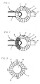
- Fig 1 shows a typical prior art current transformer with a one turn primary winding and a secondary winding, wound on a toroidal core.
- Fig 2 shows the transformer of Fig. 1 and illustrates a partially unsaturated prior art current transformer core.
- Fig 3 shows a current transformer according to the invention with four secondary winding sections, the primary winding is omitted for clarity.
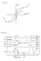
- Fig 4 shows a typical (not in scale) core material BH-curve.
- Fig 5 shows a diagram illustrating the location in time of the four states used to describe the invention. It also shows a typical secondary current waveform at positive primary current.
- Fig 6 a-c show the connection of the secondary winding in a H-bridge, and the states of this H-bridge in each of the states of the invention.
- Figure 1 illustrates a typical prior art current transformer having a primary winding 1 and a secondary winding 2, both wound on a toroidal core 3.
- Primary current 4 is transformed to a turns ratio scaled secondary current 5.
- a preferable way of implementing the primary winding 1 of a current transformer is to let the wire carrying the primary current 4, the current to be measured, be circumfered by the toroidal transformer core 3. It is of course possible to make a primary winding with more than one turn.
- Transformation of primary current to secondary current in a current transformer takes place as long as the primary current can cause a flux density change in the transformer core.
- the change of flux per unit time in a transformer core is proportional to the EMF induced in a winding and inverse proportional to the number of turns in the winding.
- the EMF in the winding is equal to the voltage applied over the winding 6 minus resistive voltage drops.
- the EMF will adjust itself, depending on the voltage over the winding, to let a secondary current flow with a magnitude equal to the turns ratio scaled magnitude of a primary current.
- the EMF can be controlled, and thereby the change of flux per unit time in the transformer core.
- a load for example a shunt resistor over the secondary winding a voltage proportional to the secondary current can be measured over this resistor.
- the basic property of the invention is to lower the losses in the measurement circuit and the secondary winding or secondary winding sections.
- the secondary current should only be allowed to flow a short period of time, before, during and after the measurement is conducted.
- the transforming function of the transformer core is disabled. Transformation takes place as long as the primary current cause a flux change in the transformer core. If the transformer core is saturated, the level of flux is at its maximum for positive saturation 16 and at its minimum for negative saturation 14. No further significant increase beyond positive saturation level and decrease beyond negative saturation level is possible.
- Positive saturation is in this document defined as the flux level the core would saturate at when short circuited by a load resistance and having positive primary current flowing in the primary winding. In case of negative primary current the core would saturate at negative saturation level, which only differs from the positive in the sense of sign.
- Figure 5 also includes an illustration of a positive secondary current waveform.
- the flux level in the current transformer core is in the linear region 15 of the BH-curve.
- the secondary winding is short circuited by a shunt resistor, to allow for measurements of secondary current by measuring the voltage over the resistor.
- the resistance must be low to keep the voltage over it low, and to keep the losses in the resistor low.
- the voltage over the secondary winding will depend on secondary current and the total resistance of the circuit including the shunt resistor, cables, winding wire and switches.
- the voltage is positive when a positive secondary current flows, the EMF will then also be positive, and the flux change in the transformer core will be positive.
- the flux level in the transformer core will increase towards positive saturation. For a negative primary current the flux will decrease towards negative saturation.
- the flux level in the transformer core is driven to saturation, during the saturation-state. This is done by applying a voltage, positive for positive primary currents and negative for negative primary currents, to the secondary winding.
- the transformer core will slowly drift towards saturation during the measurement-state. To make the drift faster during the saturation-state, a voltage greater than the measurement voltage is applied to the secondary winding.
- transformation of secondary current stops. Due to saturation the EMF will decrease towards zero.
- the secondary current is directed as to deliver power in to the secondary power supply, further reducing the total losses.
- secondary current will decrease and finally change direction when the EMF decreases below the supply voltage 40. Secondary current will now be directed as to draw power from the secondary power supply.
- Saturation of the transformer core activates the wait-state.
- the secondary winding is connected as in the measurement-state during the wait-state. No secondary current will flow as long as the current transformer core is saturated in the direction of primary current.
- For a positive primary current and positive saturation no further increase of flux is possible, and no transformation takes place.
- the primary current changes sign a decrease is possible, and a negative primary current will be transformed.
- For a negative primary current and negative saturation no further decrease of flux is possible, but an increase is possible, and positive primary current can be transformed.
- the primary current direction is detected during the measurement-state and according to this direction the core is saturated positive for positive primary current or negative for negative primary current.
- the current transformer core is desaturated, driven in to the linear region of the material BH-curve.
- a negative voltage is applied over the secondary winding. This will make the EMF negative and a negative flux change will take place.
- the flux level in the core will decrease from positive saturation level in to the linear region of the material BH-curve.
- a positive voltage is applied for negative directed primary current. This results in a positive EMF and the flux level in the core increase from negative saturation into the linear region.
- primary current is transformed to a turns-ratio scaled secondary current.
- the duration of the saturation-state is predetermined to a fixed time.
- the time must be long enough to drive the transformer core into the linear part of the core material BH-curve. It must also be long enough to allow for the secondary current to rise 23 to the amplitude 24 of the turns-ratio scaled primary current amplitude. In order to get effective and low power consuming measurements this time has to be reduced as much as possible.
- the rise time of the secondary current is limited by leakage inductances and effects caused by asymmetric magnetic fields.
- the leakage inductance of the secondary winding or the secondary winding sections can be minimised by minimising the number of secondary turns and using a core size with a small cross sectional area compared to the radius.
- the entire core must be in the linear region in order to get a turns-ratio scaled secondary current. If the flux level in some parts of the core is in the non-linear region or at saturation level, secondary current magnitude will differ from the turns-ratio scaled primary current magnitude.
- the desaturation-state duration must be long enough to allow for the entire core to reach a flux level within the linear region of the core material BH-curve. If the core is exposed to asymmetric magnetic fields, for example caused by a asymmetrically placed primary winding, or external fields originating from somewhere else, the parts of the core exposed to less magnetic field desaturates before parts exposed to more magnetic field. EMF in the first desaturated parts will decrease the current rise in the whole secondary winding.
- the secondary winding is divided in two or more separate winding sections.
- Each secondary winding section is locally wound at one bounded sector of the core. This is illustrated in figure 3 for the case of four secondary winding sections 10,11,12,13 the primary winding is omitted for clarity.
- the control of the transformer is done with a H-bridge connected as in figure 6.
- the controllable switches 45, 46, 47, 48 are turned on and off according to state and detected direction of primary current.
- Two shunt resistors 49, 50 are used to simplify detection of saturation and to keep the measured voltage close to ground.
- the low-side switches 47, 48 are turned on, and 45, 46 are turned off, independent of current direction. This is illustrated in figure 6b, for a positive primary current.
- the secondary current produces a proportional voltage drop over the two resistors 49, 50.
- the voltage 42 will, for positive primary current, drive the core towards positive saturation, and for negative primary current towards negative saturation. The drift will be slow because to lower the losses low valued resistors is used, and the voltage over these low valued resistors will be lower than the supply voltage.
- the secondary winding When saturation is detected, during wait-state, the secondary winding is connected as in the measurement state. This will keep the flux level at saturation if the current direction does not change, with no secondary current flow as result. If the primary current changes direction, the low voltage over the resistors 49, 50 will make the core drive slowly out of saturation. The slow drive out of saturation when current has changed sign is important, because if the flux level is to far away from it's original saturated level when the desaturation-state starts, the core could be driven into saturation in the opposite direction.
Landscapes
- Engineering & Computer Science (AREA)
- Power Engineering (AREA)
- Physics & Mathematics (AREA)
- General Physics & Mathematics (AREA)
- Transformers For Measuring Instruments (AREA)
- Measuring Instrument Details And Bridges, And Automatic Balancing Devices (AREA)
Applications Claiming Priority (2)
| Application Number | Priority Date | Filing Date | Title |
|---|---|---|---|
| SE0301961A SE525864C2 (sv) | 2003-07-03 | 2003-07-03 | Metod och anordning för strömmätning med strömtranformatorer vid stora strömmar |
| SE0301961 | 2003-07-03 |
Publications (1)
| Publication Number | Publication Date |
|---|---|
| EP1494033A1 true EP1494033A1 (de) | 2005-01-05 |
Family
ID=27731087
Family Applications (1)
| Application Number | Title | Priority Date | Filing Date |
|---|---|---|---|
| EP04445073A Withdrawn EP1494033A1 (de) | 2003-07-03 | 2004-06-24 | Leistungseffiziente Strommessung für hohe Ströme |
Country Status (3)
| Country | Link |
|---|---|
| US (1) | US7071678B2 (de) |
| EP (1) | EP1494033A1 (de) |
| SE (1) | SE525864C2 (de) |
Cited By (7)
| Publication number | Priority date | Publication date | Assignee | Title |
|---|---|---|---|---|
| US7372354B2 (en) | 2005-01-07 | 2008-05-13 | Danfysik A/S | Detector circuit to be used for measuring current |
| WO2008058981A3 (de) * | 2006-11-15 | 2008-07-10 | Continental Automotive Gmbh | Anordnung und verfahren zur ermittlung von lastströmen in einem fahrzeug |
| GB2476637A (en) * | 2009-07-22 | 2011-07-06 | Lilco Ltd | Wideband voltage measurement transformer |
| WO2015122855A1 (en) * | 2014-02-11 | 2015-08-20 | Grňo Ladislav | Sensor and method for electric current measurement |
| CN105405626A (zh) * | 2015-12-29 | 2016-03-16 | 无锡应达工业有限公司 | 一种大功率中高频电源用电流互感器及绕制方法 |
| EP2597658A3 (de) * | 2011-11-22 | 2017-12-06 | ABB Schweiz AG | Stromtransformator |
| EP4644915A1 (de) | 2024-04-30 | 2025-11-05 | Applied Invest s.r.o. | Planarer sensor und elektrischer stromsensor |
Families Citing this family (11)
| Publication number | Priority date | Publication date | Assignee | Title |
|---|---|---|---|---|
| DE102008029475A1 (de) * | 2008-06-20 | 2009-12-24 | Robert Bosch Gmbh | Stromsensoranordnung zur Messung von Strömen in einem Primärleiter |
| DE102008029477A1 (de) * | 2008-06-20 | 2009-12-24 | Vacuumschmelze Gmbh & Co. Kg | Stromsensoranordnung zur Messung von Strömen in einem Primärleiter |
| US8929053B2 (en) * | 2010-09-13 | 2015-01-06 | William Henry Morong | Direct-current current transformer |
| US8531858B2 (en) * | 2011-02-18 | 2013-09-10 | Ideal Power, Inc. | Power conversion with current sensing coupled through saturating element |
| DE102011001147A1 (de) | 2011-03-08 | 2012-09-13 | Sma Solar Technology Ag | Vormagnetisierte AC-Drossel mit Polwender |
| EP2747270B1 (de) * | 2012-12-21 | 2014-10-15 | Inmotion Technologies AB | Brückenzweig |
| WO2015070345A1 (en) * | 2013-11-12 | 2015-05-21 | The University Of Manitoba | Simultaneous measurement technique for line current, geomagnetically induced currents (gic) and transient currents in power systems |
| US10381155B2 (en) * | 2015-08-18 | 2019-08-13 | New York University | Winding for low-voltage coils of distribution-class toroidal transformers |
| CN105374507B (zh) * | 2015-11-30 | 2017-07-14 | 国家电网公司 | 弧形铁芯线圈电流互感器及其制作方法 |
| CN105353195B (zh) * | 2015-12-10 | 2018-06-05 | 国家电网公司 | Cvt泄漏电流无源零磁通取样装置 |
| US9618541B1 (en) * | 2016-04-20 | 2017-04-11 | Neilsen-Kuljian, Inc. | Apparatus, method and device for sensing DC currents |
Citations (4)
| Publication number | Priority date | Publication date | Assignee | Title |
|---|---|---|---|---|
| GB740467A (en) * | 1953-02-02 | 1955-11-16 | Foster Transformers Ltd | Improvements in current transformers |
| US4823074A (en) * | 1987-12-15 | 1989-04-18 | The United States Of America As Represented By The Administrator Of The National Aeronautics And Space Administration | Low power consumption current transducer |
| US5814983A (en) * | 1996-06-07 | 1998-09-29 | Hughes Electronics Corporation | Method for sensing DC current and sensor for carrying out same |
| US20030058596A1 (en) * | 2000-03-04 | 2003-03-27 | Macbeth Bruce F. | Two winding resonating arc fault sensor which boosts arc fault signals while rejecting arc mimicking noise |
Family Cites Families (8)
| Publication number | Priority date | Publication date | Assignee | Title |
|---|---|---|---|---|
| US4298838A (en) * | 1976-01-14 | 1981-11-03 | Mitsubishi Denki Kabushiki Kaisha | Transformer device |
| US3996543A (en) * | 1976-02-04 | 1976-12-07 | Westinghouse Electric Corporation | Current transformer |
| US4320433A (en) * | 1980-03-21 | 1982-03-16 | Fuji Electric Co., Ltd. | Earth-leakage-current circuit breaker system |
| US4482862A (en) * | 1982-06-10 | 1984-11-13 | The Charles Stark Draper Laboratory, Inc. | Current sensor |
| JPH03185362A (ja) * | 1989-12-14 | 1991-08-13 | Mitsubishi Electric Corp | 変流器 |
| US5053695A (en) * | 1990-03-09 | 1991-10-01 | Space Systems/Loral, Inc. | Dc current monitor |
| US5552979A (en) * | 1993-11-30 | 1996-09-03 | Philips Electronics North America Corporation | Isolated current sensor for DC to high frequency applications |
| US5811965A (en) * | 1994-12-28 | 1998-09-22 | Philips Electronics North America Corporation | DC and AC current sensor having a minor-loop operated current transformer |
-
2003
- 2003-07-03 SE SE0301961A patent/SE525864C2/sv not_active IP Right Cessation
-
2004
- 2004-06-24 EP EP04445073A patent/EP1494033A1/de not_active Withdrawn
- 2004-06-29 US US10/881,844 patent/US7071678B2/en not_active Expired - Fee Related
Patent Citations (4)
| Publication number | Priority date | Publication date | Assignee | Title |
|---|---|---|---|---|
| GB740467A (en) * | 1953-02-02 | 1955-11-16 | Foster Transformers Ltd | Improvements in current transformers |
| US4823074A (en) * | 1987-12-15 | 1989-04-18 | The United States Of America As Represented By The Administrator Of The National Aeronautics And Space Administration | Low power consumption current transducer |
| US5814983A (en) * | 1996-06-07 | 1998-09-29 | Hughes Electronics Corporation | Method for sensing DC current and sensor for carrying out same |
| US20030058596A1 (en) * | 2000-03-04 | 2003-03-27 | Macbeth Bruce F. | Two winding resonating arc fault sensor which boosts arc fault signals while rejecting arc mimicking noise |
Cited By (9)
| Publication number | Priority date | Publication date | Assignee | Title |
|---|---|---|---|---|
| US7372354B2 (en) | 2005-01-07 | 2008-05-13 | Danfysik A/S | Detector circuit to be used for measuring current |
| WO2008058981A3 (de) * | 2006-11-15 | 2008-07-10 | Continental Automotive Gmbh | Anordnung und verfahren zur ermittlung von lastströmen in einem fahrzeug |
| GB2476637A (en) * | 2009-07-22 | 2011-07-06 | Lilco Ltd | Wideband voltage measurement transformer |
| GB2476637B (en) * | 2009-07-22 | 2014-06-18 | Lilco Ltd | Wideband voltage measurement transformer |
| EP2597658A3 (de) * | 2011-11-22 | 2017-12-06 | ABB Schweiz AG | Stromtransformator |
| WO2015122855A1 (en) * | 2014-02-11 | 2015-08-20 | Grňo Ladislav | Sensor and method for electric current measurement |
| US9989562B2 (en) | 2014-02-11 | 2018-06-05 | Ladislav Gr{hacek over (n)}o | Sensor and method for electric current measurement |
| CN105405626A (zh) * | 2015-12-29 | 2016-03-16 | 无锡应达工业有限公司 | 一种大功率中高频电源用电流互感器及绕制方法 |
| EP4644915A1 (de) | 2024-04-30 | 2025-11-05 | Applied Invest s.r.o. | Planarer sensor und elektrischer stromsensor |
Also Published As
| Publication number | Publication date |
|---|---|
| SE525864C2 (sv) | 2005-05-17 |
| US20050001706A1 (en) | 2005-01-06 |
| SE0301961L (sv) | 2005-01-04 |
| SE0301961D0 (sv) | 2003-07-03 |
| US7071678B2 (en) | 2006-07-04 |
Similar Documents
| Publication | Publication Date | Title |
|---|---|---|
| US7071678B2 (en) | Low power consuming current measurements for high currents | |
| US6479976B1 (en) | Method and apparatus for accurate measurement of pulsed electric currents utilizing ordinary current transformers | |
| US5565765A (en) | Current sensor operating according to the compensation theorem | |
| US5146156A (en) | Current intensity transformer device for measuring a variable electric current | |
| US5345169A (en) | Current measuring device | |
| US5309086A (en) | Current measuring transducer operating on the compensation principle | |
| US4152637A (en) | Saturable reactor limiter for current | |
| US7242157B1 (en) | Switched-voltage control of the magnetization of current transforms and other magnetic bodies | |
| KR20020027491A (ko) | 교류전류 검출장치 | |
| EP2485061B1 (de) | Aktivkernstromsensor | |
| US4286211A (en) | Direct current detecting device using saturable reactors | |
| EP2950314B1 (de) | Sättigungsregelung von magnetkernen bidirektionaler vorrichtungen | |
| JPH1140429A (ja) | 変圧器及び変圧器の直流偏磁検出素子、並びに直流偏磁評価装置 | |
| JPH1054848A (ja) | 電流補償形電流センサ | |
| JP4016750B2 (ja) | 磁気検出装置 | |
| JP2003524765A (ja) | パルス幅変調された増幅器における電流を測定するための改善された動的応答を持つ回路 | |
| US4377758A (en) | Magnetic amplifying apparatus | |
| JP3114890B2 (ja) | 電動カーテン駆動装置 | |
| RU2138824C1 (ru) | Датчик тока | |
| JP3035728B2 (ja) | 節電装置 | |
| SU1285386A1 (ru) | Устройство дл воспроизведени значений больших посто нных токов | |
| JP2003217952A (ja) | 電流トランス | |
| JPH0470518A (ja) | 電磁流量計 | |
| JPH0244261A (ja) | 電流検出方法および電源装置 | |
| SU930177A1 (ru) | Устройство дл контрол магнитных свойств сердечников разомкнутой формы |
Legal Events
| Date | Code | Title | Description |
|---|---|---|---|
| PUAI | Public reference made under article 153(3) epc to a published international application that has entered the european phase |
Free format text: ORIGINAL CODE: 0009012 |
|
| AK | Designated contracting states |
Kind code of ref document: A1 Designated state(s): AT BE BG CH CY CZ DE DK EE ES FI FR GB GR HU IE IT LI LU MC NL PL PT RO SE SI SK TR |
|
| AX | Request for extension of the european patent |
Extension state: AL HR LT LV MK |
|
| 17P | Request for examination filed |
Effective date: 20050623 |
|
| AKX | Designation fees paid |
Designated state(s): DE FR GB IT |
|
| STAA | Information on the status of an ep patent application or granted ep patent |
Free format text: STATUS: EXAMINATION IS IN PROGRESS |
|
| 17Q | First examination report despatched |
Effective date: 20100331 |
|
| STAA | Information on the status of an ep patent application or granted ep patent |
Free format text: STATUS: THE APPLICATION IS DEEMED TO BE WITHDRAWN |
|
| 18D | Application deemed to be withdrawn |
Effective date: 20100811 |