EP1493983A1 - Loop-type thermosiphon and stirling refrigerator - Google Patents
Loop-type thermosiphon and stirling refrigerator Download PDFInfo
- Publication number
- EP1493983A1 EP1493983A1 EP03745945A EP03745945A EP1493983A1 EP 1493983 A1 EP1493983 A1 EP 1493983A1 EP 03745945 A EP03745945 A EP 03745945A EP 03745945 A EP03745945 A EP 03745945A EP 1493983 A1 EP1493983 A1 EP 1493983A1
- Authority
- EP
- European Patent Office
- Prior art keywords
- evaporator
- working fluid
- loop
- heat
- condenser
- Prior art date
- Legal status (The legal status is an assumption and is not a legal conclusion. Google has not performed a legal analysis and makes no representation as to the accuracy of the status listed.)
- Withdrawn
Links
Images



Classifications
-
- F—MECHANICAL ENGINEERING; LIGHTING; HEATING; WEAPONS; BLASTING
- F25—REFRIGERATION OR COOLING; COMBINED HEATING AND REFRIGERATION SYSTEMS; HEAT PUMP SYSTEMS; MANUFACTURE OR STORAGE OF ICE; LIQUEFACTION SOLIDIFICATION OF GASES
- F25B—REFRIGERATION MACHINES, PLANTS OR SYSTEMS; COMBINED HEATING AND REFRIGERATION SYSTEMS; HEAT PUMP SYSTEMS
- F25B25/00—Machines, plants or systems, using a combination of modes of operation covered by two or more of the groups F25B1/00 - F25B23/00
- F25B25/005—Machines, plants or systems, using a combination of modes of operation covered by two or more of the groups F25B1/00 - F25B23/00 using primary and secondary systems
-
- F—MECHANICAL ENGINEERING; LIGHTING; HEATING; WEAPONS; BLASTING
- F28—HEAT EXCHANGE IN GENERAL
- F28D—HEAT-EXCHANGE APPARATUS, NOT PROVIDED FOR IN ANOTHER SUBCLASS, IN WHICH THE HEAT-EXCHANGE MEDIA DO NOT COME INTO DIRECT CONTACT
- F28D15/00—Heat-exchange apparatus with the intermediate heat-transfer medium in closed tubes passing into or through the conduit walls ; Heat-exchange apparatus employing intermediate heat-transfer medium or bodies
- F28D15/02—Heat-exchange apparatus with the intermediate heat-transfer medium in closed tubes passing into or through the conduit walls ; Heat-exchange apparatus employing intermediate heat-transfer medium or bodies in which the medium condenses and evaporates, e.g. heat pipes
-
- F—MECHANICAL ENGINEERING; LIGHTING; HEATING; WEAPONS; BLASTING
- F25—REFRIGERATION OR COOLING; COMBINED HEATING AND REFRIGERATION SYSTEMS; HEAT PUMP SYSTEMS; MANUFACTURE OR STORAGE OF ICE; LIQUEFACTION SOLIDIFICATION OF GASES
- F25D—REFRIGERATORS; COLD ROOMS; ICE-BOXES; COOLING OR FREEZING APPARATUS NOT OTHERWISE PROVIDED FOR
- F25D11/00—Self-contained movable devices, e.g. domestic refrigerators
-
- F—MECHANICAL ENGINEERING; LIGHTING; HEATING; WEAPONS; BLASTING
- F28—HEAT EXCHANGE IN GENERAL
- F28D—HEAT-EXCHANGE APPARATUS, NOT PROVIDED FOR IN ANOTHER SUBCLASS, IN WHICH THE HEAT-EXCHANGE MEDIA DO NOT COME INTO DIRECT CONTACT
- F28D15/00—Heat-exchange apparatus with the intermediate heat-transfer medium in closed tubes passing into or through the conduit walls ; Heat-exchange apparatus employing intermediate heat-transfer medium or bodies
- F28D15/02—Heat-exchange apparatus with the intermediate heat-transfer medium in closed tubes passing into or through the conduit walls ; Heat-exchange apparatus employing intermediate heat-transfer medium or bodies in which the medium condenses and evaporates, e.g. heat pipes
- F28D15/0266—Heat-exchange apparatus with the intermediate heat-transfer medium in closed tubes passing into or through the conduit walls ; Heat-exchange apparatus employing intermediate heat-transfer medium or bodies in which the medium condenses and evaporates, e.g. heat pipes with separate evaporating and condensing chambers connected by at least one conduit; Loop-type heat pipes; with multiple or common evaporating or condensing chambers
-
- F—MECHANICAL ENGINEERING; LIGHTING; HEATING; WEAPONS; BLASTING
- F25—REFRIGERATION OR COOLING; COMBINED HEATING AND REFRIGERATION SYSTEMS; HEAT PUMP SYSTEMS; MANUFACTURE OR STORAGE OF ICE; LIQUEFACTION SOLIDIFICATION OF GASES
- F25B—REFRIGERATION MACHINES, PLANTS OR SYSTEMS; COMBINED HEATING AND REFRIGERATION SYSTEMS; HEAT PUMP SYSTEMS
- F25B23/00—Machines, plants or systems, with a single mode of operation not covered by groups F25B1/00 - F25B21/00, e.g. using selective radiation effect
- F25B23/006—Machines, plants or systems, with a single mode of operation not covered by groups F25B1/00 - F25B21/00, e.g. using selective radiation effect boiling cooling systems
-
- F—MECHANICAL ENGINEERING; LIGHTING; HEATING; WEAPONS; BLASTING
- F25—REFRIGERATION OR COOLING; COMBINED HEATING AND REFRIGERATION SYSTEMS; HEAT PUMP SYSTEMS; MANUFACTURE OR STORAGE OF ICE; LIQUEFACTION SOLIDIFICATION OF GASES
- F25B—REFRIGERATION MACHINES, PLANTS OR SYSTEMS; COMBINED HEATING AND REFRIGERATION SYSTEMS; HEAT PUMP SYSTEMS
- F25B2309/00—Gas cycle refrigeration machines
- F25B2309/06—Compression machines, plants or systems characterised by the refrigerant being carbon dioxide
-
- F—MECHANICAL ENGINEERING; LIGHTING; HEATING; WEAPONS; BLASTING
- F25—REFRIGERATION OR COOLING; COMBINED HEATING AND REFRIGERATION SYSTEMS; HEAT PUMP SYSTEMS; MANUFACTURE OR STORAGE OF ICE; LIQUEFACTION SOLIDIFICATION OF GASES
- F25B—REFRIGERATION MACHINES, PLANTS OR SYSTEMS; COMBINED HEATING AND REFRIGERATION SYSTEMS; HEAT PUMP SYSTEMS
- F25B9/00—Compression machines, plants or systems, in which the refrigerant is air or other gas of low boiling point
- F25B9/14—Compression machines, plants or systems, in which the refrigerant is air or other gas of low boiling point characterised by the cycle used, e.g. Stirling cycle
-
- F—MECHANICAL ENGINEERING; LIGHTING; HEATING; WEAPONS; BLASTING
- F25—REFRIGERATION OR COOLING; COMBINED HEATING AND REFRIGERATION SYSTEMS; HEAT PUMP SYSTEMS; MANUFACTURE OR STORAGE OF ICE; LIQUEFACTION SOLIDIFICATION OF GASES
- F25D—REFRIGERATORS; COLD ROOMS; ICE-BOXES; COOLING OR FREEZING APPARATUS NOT OTHERWISE PROVIDED FOR
- F25D23/00—General constructional features
- F25D23/003—General constructional features for cooling refrigerating machinery
Definitions
- the present invention relates to a loop-type thermosiphon and a Stirling refrigerator using the same.
- a heat sink, a heat pipe, a thermosiphon, or the like is used for cooling a heat-generating instrument or a thermoelectric cooling device.
- the heat sink temperature distribution is caused in a base portion thereof provided with a heat source. Accordingly, as a distance from the heat source is increased, the heat sink contributes less to heat dissipation.
- the heat pipe or the thermosiphon has high heat transfer capability, and is characterized by small temperature variation even when the heat is transferred to a portion distant from the heat source.
- vapor and liquid of a working fluid flows in the same pipe.
- a greater number of pipes are necessary.
- a heat pipe having an outer diameter of 15.8mm and a length of 300mm attains an amount of heat transfer of approximately 100W.
- a heat pipe including a condensation portion having a large heat transfer area should be provided in order to exchange heat with air, because a heat transfer coefficient of the air is low.
- a pipe-shaped thermosiphon in which a liquid returns to an evaporation portion by gravity also has the similar characteristic.
- a loop-type thermosiphon is also structured such that the liquid condensed in a condenser returns to an evaporator by gravity.
- the condenser can be designed in accordance with cooling means of the condenser, but also the evaporator can be designed in accordance with a shape and a size of the heat source. Therefore, two pipes, i.e., a gas pipe and a liquid pipe connecting the condenser and the evaporator are enough in most cases.
- the condenser has to be located above the evaporator.
- a newly developed HFC-based refrigerant though not destroying the ozone layer, is a potent greenhouse substance attaining a global warming coefficient several hundred to several thousand or more times larger than carbon dioxide, and subject to effluent control. Therefore, types of refrigerants that can be selected as a working fluid for the loop-type thermosiphon are limited from a viewpoint of environmental protection. Examples of an environmental-friendly and what is called natural refrigerant include a medium such as an HC-based refrigerant, ammonia, carbon dioxide, water, and ethanol, and a mixture thereof.
- a conventional loop-type thermosiphon is structured by connecting an evaporator 101, a condenser 103 and a gas-liquid separation tank 106 using pipes 102, 104.
- a heat source 105 is cooled in evaporator 101.
- Condenser 103 is provided above evaporator 101.
- the working fluid liquefied in condenser 103 is separated to gas and liquid in gas-liquid separation tank 106 provided between the condenser and the evaporator.
- the liquid of the working fluid runs through pipe 104 by gravity, and is introduced in the evaporator from a lower portion of evaporator 101.
- the working fluid that has deprived the heat source of heat is vaporized in evaporator 101, and the vapor of the working fluid is introduced in condenser 103 through pipe 102 by a vapor pressure difference between the condenser and the evaporator.
- evaporator 101 is designed in accordance with the shape of the heat source.
- gas-liquid separation tank 106 is not essential.
- Japanese Patent Laying-Open No. 11-223404 discloses a method of cooling a high-temperature portion of a Stirling cooler with a liquid of a secondary refrigerant by means of a pump.
- the loop-type thermosiphon is utilized for cooling a high-temperature portion of a Stirling cooler and the Stirling cooler is mounted on a refrigerator, for example.
- heat load of the refrigerator fluctuates depending on the season.
- an amount of heat dissipation from the high-temperature portion of the Stirling cooler is also varied.
- the loop-type thermosiphon often exhibits an unstable operation under fluctuating heat load.
- the temperature of the high-temperature portion of the Stirling cooler fluctuates significantly, an influence therefrom is not limited to fluctuation of a COP (Coefficient of Performance) of the Stirling cooler. If the temperature of the high-temperature portion is excessively high, a regenerator of the Stirling cooler may be destroyed.
- COP Coefficient of Performance
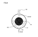
- Fig. 6 shows an evaporator for the conventional loop-type thermosiphon cooling the heat source having a cylindrical shape.
- Evaporator 101 has an annular shape in order to cool cylindrical heat source 105.
- Cylindrical heat source 105 is fitted in a hole of the evaporator, so as to be in intimate contact with a surface of the hole of the evaporator.
- the surface of the hole of the evaporator is provided with an internal fin (not shown) for increasing an evaporation area.
- the liquid from the condenser runs through pipe 104 and flows into a liquid pool 121 through a lower portion of the evaporator, and the vapor exits from an upper portion of the evaporator through pipe 102 and flows to the condenser.
- Fig. 7 shows variation of the temperature of the heat source in an experimental operation of the loop-type thermosiphon employing the evaporator and the pipe arrangement shown in Fig. 6 and containing water as a working fluid. If an amount of heat generation from the heat source is not larger than 75% of designed load, fluctuation of the temperature of the heat source is caused as shown in Fig. 7. Improvement was not observed even when a contained amount of the working fluid was changed.
- An object of the present invention is to provide a loop-type thermosiphon capable of maintaining a stable temperature of a high-temperature heat source in spite of large fluctuation of heat load and a Stirling refrigerator equipped with the same.
- a loop-type thermosiphon according to the present invention transfers heat from a high-temperature heat source using a working fluid.
- the loop-type thermosiphon includes: an evaporator having a heat absorption portion and evaporating the working fluid by depriving the high-temperature heat source of heat through the heat absorption portion; a condenser located above the high-temperature heat source and condensing the working fluid that has evaporated in the evaporator; and a pipe connecting the evaporator and the condenser so as to form a loop.
- the working fluid that has passed through the condenser is brought in contact with the heat absorption portion before it is pooled in a liquid pool for the working fluid in the evaporator
- the cooled working fluid is preheated by the heat absorption portion instead of being directly supplied to the liquid pool, and thereafter it is supplied from above by gravitation. Accordingly, a flow is produced in the liquid pool and evaporation of the working fluid as a whole, including the working fluid in the liquid pool, is promoted.
- evaporation of the working fluid that has been introduced and initially exchanges heat with the heat absorption portion is also promoted in an ensured manner, whereby temperature distribution in the high-temperature heat source can be uniform.
- separation of bubbles adhered to the heat absorption portion or the like can be promoted. Therefore, heat exchange adapted to fluctuation of the heat load can be performed, and the temperature of the high-temperature heat source can be stabilized.
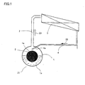
- Fig. 1 illustrates a basic arrangement of a loop-type thermosiphon in a first embodiment of the present invention.
- Fig. 2 shows a variation of the loop-type thermosiphon in the first embodiment of the present invention.
- Fig. 3 shows a Stirling refrigerator in a second embodiment of the present invention.
- Fig. 4 shows stability of a temperature of a heat source when a loop-type thermosiphon in a third embodiment of the present invention is employed.
- Fig. 5 shows an arrangement of a general loop-type thermosiphon.
- Fig. 6 shows an evaporator in a conventional loop-type thermosiphon.
- Fig. 7 shows fluctuation of a temperature of a heat source when the conventional loop-type thermosiphon is used.
- Fig. 1 is a conceptual diagram illustrating a basic arrangement of a loop-type thermosiphon in a first embodiment of the present invention.
- the loop-type thermosiphon shown in Fig. 1 is constituted of an evaporator 1, a condenser 3, a gas pipe 2 extending from evaporator 1 to condenser 3, and a liquid pipe 4 extending from condenser 3 to evaporator 1.
- a high-temperature heat source 5 to be cooled has a cylindrical heat dissipation surface as shown in Fig. 1, the evaporator has an annular shape with a circular hole having a dimension adapted to the cylindrical heat dissipation surface of the heat source.
- Condenser 3 is of a fin-tube type, and cools a working fluid flowing inside the pipe by flowing air around the same.
- the pipe of the condenser for flowing the working fluid may be any of a parallel flow type and a serpentine type.
- the condenser is provided such that an inlet of a gas is located higher than an outlet of a condensed liquid.
- Gas pipe 2 extending from evaporator 1 to condenser 3 has a larger diameter than liquid pipe 4 extending from the condenser to the evaporator. Therefore, gas pipe 2 has a flow resistance smaller than liquid pipe 4, so as to prevent backflow of the working fluid and hard starting.
- a diameter of the liquid pipe is determined based on designed heat load and thermal property of the working fluid.
- condenser 3 is located above evaporator 1.
- pure water is contained as the working fluid.
- a contained amount is assumed as a mass of the working fluid of which liquid fills 1/3 to 2/3 of a total of a possible volume of liquid pool in the condenser (a header pipe at an outlet of the condenser, for example), a volume of the liquid pipe and a volume of the evaporator, and of which saturated vapor fills a remaining volume at an operating temperature.
- Such a contained amount allows smooth operation of the working fluid.
- the water evaporates by depriving high-temperature heat source 5 of heat in evaporator 1.
- the vapor produced in evaporator 1 runs through gas pipe 2 utilizing a vapor pressure difference caused by a temperature difference between condenser 3 and evaporator 1 and flows in condenser 3, in which the vapor is deprived of heat by the air outside the pipe and condensed.
- the liquid condensed in condenser 3 returns to evaporator 1 through liquid pipe 4 by gravity. In this manner, a process including circulation of the working fluid, heat absorption in the evaporator, and heat dissipation in the condenser is repeated.
- One feature of the embodiment of the present invention resides in introduction of the liquid from the condenser through the upper portion of the evaporator as shown in Fig. 1, instead of introduction through the lower portion thereof (see Fig. 5).
- a cold liquid is supplied to the lower portion of the evaporator. Accordingly, a temperature gradient in the liquid pooled in the evaporator does not considerably affect the flow, without promoting evaporation. If the evaporator operates under a condition far from the designed heat load, particularly under such a condition as small heat load, bubbles adhered to a heat transfer surface takes longer time in growth.
- the liquid from the condenser is introduced through the upper portion of the evaporator, so that the supercooled liquid initially falls on a heat absorption portion at a high temperature or on a not-shown internal fin, on which the liquid is preheated.
- the internal fin is attached to the heat absorption portion and formed inwardly, so that evaporation of the liquid pooled in the evaporator is promoted.
- the liquid tends to move downward by gravity due to a difference in density.
- the loop-type thermosiphon according to the present embodiment can achieve a stable temperature of the heat source even under a condition far from the designed heat load.
- gas-liquid separation tank 6 may be provided between the condenser and the evaporator as shown in Fig. 2. It is noted, however, that an inner volume of the gas-liquid separation tank should be regarded as a portion of the liquid pipe in determining a contained amount. Provision of the gas-liquid separation tank may be effective for attaining a stable operation of the loop-type thermosiphon.
- Addition of ethanol to the water serving as the working fluid by not larger than 60% can lower a tolerable temperature of an environment during operation or transportation.
- Fig. 3 is a conceptual diagram of a Stirling refrigerator according to a second embodiment of the present invention, provided with the loop-type thermosiphon.
- the Stirling refrigerator in Fig. 3 is constituted of a Stirling cooler provided in a refrigerator main body 19, the loop-type thermosiphon attached in order to cool a high-temperature portion of the Stirling cooler, a low-temperature side heat exchange system transferring a cold of a low-temperature portion of the Stirling cooler to the inside of the refrigerator, the refrigerator main body, and the like.
- the low-temperature side heat exchange system is implemented by the loop-type thermosiphon, it is the loop-type thermosiphon not of interest in the present embodiment.
- a Stirling cooler 11 having cylindrical high-temperature and low-temperature portions is arranged on a back surface of the refrigerator.
- Evaporator 1 of the loop-type thermosiphon cooling a high-temperature portion 13 of the Stirling cooler is attached to and brought in intimate contact with the high-temperature portion of the Stirling cooler.
- condenser 3 is placed on the refrigerator main body and evaporator 1 and condenser 3 are connected to each other by a pipe as shown in Fig. 1, so that the loop-type thermosiphon in the present embodiment is mounted on the Stirling refrigerator.
- Liquid pipe 4 is inserted in evaporator 1 through its upper portion.
- pure water or a mixture of pure water and ethanol is contained.
- the low-temperature side heat exchange system supplies the cold of a low-temperature portion 12 of the Stirling cooler to the inside of the refrigerator with a refrigerator cooling apparatus 15 utilizing a secondary refrigerant.
- Refrigerator cooling apparatus 15 is provided in a cold-air duct in the refrigerator.
- Stirling cooler 11 serves to lower the temperature of low-temperature portion 12, and the secondary refrigerant in the heat exchange system flowing through the low-temperature portion is deprived of heat.
- the secondary refrigerant in the low-temperature side heat exchange system absorbs heat from the air inside the refrigerator in the refrigerator cooling apparatus by rotation of a cooling fan 16 on which a damper 17 is arranged.
- the secondary refrigerant in the low-temperature side heat exchange system attains natural circulation by gravity. Alternatively, circulation may naturally be attained by circulation means using a pump. As described above, the cold of Stirling cooler 11 is continuously provided to the air inside the refrigerator.
- drain water resulting from defrosting of refrigerator cooling apparatus 15 is discharged from a drain water outlet 18.
- Fig. 4 shows temperature fluctuation of the high-temperature heat source when a loop-type thermosiphon according to a third embodiment of the present invention is employed.
- the loop-type thermosiphon in the present embodiment is obtained merely by varying a manner of return of the liquid to the evaporator in the conventional loop-type thermosiphon shown in Fig. 6.
- the loop-type thermosiphon is structured such that the condensed working fluid is returned so as to contact with the heat absorption portion not being in contact with the liquid pool, instead of being directly introduced into the liquid pool.
- the variation with time of the temperature of the high-temperature heat source shown in Fig. 4 exhibits an effect obtained under the condition of heat load the same as in the conventional loop-type thermosiphon.
- stable temperature transition can be achieved.
- a loop-type thermosiphon transferring heat from a high-temperature heat source having a heat dissipation surface includes an evaporator depriving the high-temperature heat source of heat, a condenser arranged above the high-temperature heat source, and a pipe connecting the evaporator and the condenser so as to form a loop.
- the loop-type thermosiphon contains a working fluid, and drops the liquid of the working fluid from the condenser on a heat absorption portion when it is introduced in the evaporator, so as to exchange heat. Therefore, a loop-type thermosiphon capable of maintaining a stable temperature of the high-temperature heat source can be provided.
- an internal fin is provided in the heat absorption portion in the evaporator constituting the loop-type thermosiphon, and the liquid of the working fluid condensed in the condenser is introduced in the evaporator through the upper portion thereof, so that the liquid of the working fluid falls on the heat absorption portion or the internal fin in the evaporator.
- the evaporator may have a box-shape, or may have an annular shape by combining semi-annular portions. Alternatively, combination of portions of another shape may be employed.
- the heat absorption portion may be of a cylindrical shape or formed like a hole so as to receive the high-temperature heat source.
- the liquid of the working fluid can be preheated and a uniform and stable temperature of the high-temperature heat source in the evaporator can be achieved.
- a flow resistance of the gas pipe guiding vapor produced in the evaporator to the condenser is made smaller than that of the liquid pipe guiding the liquid condensed in the condenser to the evaporator. According to such an arrangement, backflow of the working fluid and hard starting likely in the thermosiphon can be prevented.
- the flow resistance of the pipe is made smaller if the amount of transferred heat is large, and it is made larger if the amount of transferred heat is small. If a diameter of the pipe is determined based on such an arrangement, more stable circulation flow rate of the working fluid can be achieved.
- a reference value of magnitude of an amount of transferred heat may be set to 75% of the designed load, for example. That is, if an amount of heat generation from the heat source is not larger than 75% of the designed load, the flow resistance of the pipe is made larger, and if it exceeds 75%, the flow resistance of the pipe is made smaller.
- another reference value such as 50% of the designed load may be adopted.
- a contained amount of the working fluid can be set to a mass of the working fluid of which liquid fills 1/3 to 2/3 of a total of a possible volume of liquid pool in the condenser at an operating temperature, a volume of the liquid pipe (the pipe) and a volume of the evaporator, and of which saturated vapor fills a remaining volume at the operating temperature. Accordingly, a disadvantage resulting from a contained amount of the working fluid can be eliminated.
- a loop-type thermosiphon according to yet another embodiment of the present invention employs a natural refrigerant such as carbonic acid gas, water, hydrocarbon, or the like as the working fluid, and can provide an environment-friendly heat exchange technique. Particularly when water is employed as the working fluid, a safe loop-type thermosiphon free from a toxic or flammable property can be obtained. Addition of ethanol by not larger than 60% can expand a range of temperature in an environment in which the loop-type thermosiphon employing water as the working fluid can operate.
- the evaporator of the loop-type thermosiphon described above exchanges heat with the high-temperature portion of the Stirling cooler.
- both of these components are brought in intimate contact with each other.
- the condenser can be arranged in a position higher than that of the high-temperature portion of the Stirling cooler of the refrigerator. According to such an arrangement, even when heat load of the Stirling refrigerator is varied, the Stirling cooler can achieve a stable operation.
- the working fluid achieves natural circulation by gravity, it is not necessary to provide a pump. Therefore, high reliability and efficiency can effectively be achieved.
- the loop-type thermosiphon according to the present invention can absorb fluctuation of heat load of the heat source and attain a stable operation. Therefore, the loop-type thermosiphon described above is used for cooling the high-temperature portion of the Stirling cooler in the refrigerator employing as a cooling apparatus the Stirling cooler without using CFC and free from greenhouse gas emission, for example.
- the loop-type thermosiphon is expected to contribute to ensuring stable freezing performance throughout a year.
Landscapes
- Engineering & Computer Science (AREA)
- Physics & Mathematics (AREA)
- Thermal Sciences (AREA)
- Mechanical Engineering (AREA)
- General Engineering & Computer Science (AREA)
- Life Sciences & Earth Sciences (AREA)
- Sustainable Development (AREA)
- Chemical & Material Sciences (AREA)
- Combustion & Propulsion (AREA)
- Devices That Are Associated With Refrigeration Equipment (AREA)
- Heat-Exchange Devices With Radiators And Conduit Assemblies (AREA)
- Sorption Type Refrigeration Machines (AREA)
Abstract
Description
Claims (9)
- A loop-type thermosiphon transferring heat from a high-temperature heat source (5) using a working fluid (22, 23), comprising:whereinan evaporator (1) having a heat absorption portion (1a) and evaporating said working fluid by depriving said high-temperature heat source of heat through the heat absorption portion;a condenser (3) located above said high-temperature heat source and condensing the working fluid (23) that has evaporated in said evaporator; anda pipe (2, 4) connecting said evaporator and said condenser so as to form a loop;
said working fluid (22) that has passed through said condenser is brought in contact with said heat absorption portion (1a) before it is pooled in a liquid pool (21) for the working fluid in said evaporator. - The loop-type thermosiphon according to claim 1, wherein
said evaporator (1) has the heat absorption portion (1a) provided so as to receive said high-temperature heat source (5), and said working fluid condensed in said condenser is introduced so as to fall on the heat absorption portion in said evaporator from an upper portion of said evaporator. - The loop-type thermosiphon according to claim 1, wherein
a flow resistance of said pipe (2) guiding the working fluid (23) that has evaporated in said evaporator (1) to said condenser (3) is made smaller than a flow resistance of said pipe (4) guiding the working fluid (22) condensed in said condenser (3) to said evaporator (1). - The loop-type thermosiphon according to claim 1, wherein
in accordance with an amount of heat transfer from said high-temperature heat source, if the amount of heat transfer is large, the flow resistance of the pipe from said condenser to said evaporator is made smaller, and if the amount of heat transfer is small, the flow resistance of the pipe from said condenser to said evaporator is made larger. - The loop-type thermosiphon according to claim 1, wherein
a contained amount of the working fluid refers to such a contained amount that 1/3 to 2/3 of a total volume of a possible volume of liquid pool in said condenser at an operation temperature, a volume of the pipe and a volume of the evaporator is filled with a liquid of said working fluid and a remaining volume of said total volume is filled with saturated vapor of said working fluid. - The loop-type thermosiphon according to claim 1, wherein
a natural refrigerant is used as the working fluid. - The loop-type thermosiphon according to claim 1, wherein
any one of carbon dioxide, water, hydrocarbon, ammonia, ethanol, and a mixture thereof is used as the working fluid. - The loop-type thermosiphon according to claim 1, wherein
a mixture containing ethanol by at most 60% is used as the working fluid. - A Stirling refrigerator provided with a Stirling cooler (11); wherein
said Stirling cooler includes the loop-type thermosiphon according to claim 1,
said evaporator (1) exchanges heat with a high-temperature portion (13) of said Stirling cooler, and
said condenser (3) is located above said high-temperature portion.
Applications Claiming Priority (3)
| Application Number | Priority Date | Filing Date | Title |
|---|---|---|---|
| JP2002104896 | 2002-04-08 | ||
| JP2002104896A JP4033699B2 (en) | 2002-04-08 | 2002-04-08 | Loop thermosyphon and Stirling refrigerator |
| PCT/JP2003/004399 WO2003085345A1 (en) | 2002-04-08 | 2003-04-07 | Loop-type thermosiphon and stirling refrigerator |
Publications (2)
| Publication Number | Publication Date |
|---|---|
| EP1493983A1 true EP1493983A1 (en) | 2005-01-05 |
| EP1493983A4 EP1493983A4 (en) | 2006-06-07 |
Family
ID=28786352
Family Applications (1)
| Application Number | Title | Priority Date | Filing Date |
|---|---|---|---|
| EP03745945A Withdrawn EP1493983A4 (en) | 2002-04-08 | 2003-04-07 | Loop-type thermosiphon and stirling refrigerator |
Country Status (9)
| Country | Link |
|---|---|
| US (1) | US20050172644A1 (en) |
| EP (1) | EP1493983A4 (en) |
| JP (1) | JP4033699B2 (en) |
| KR (1) | KR100691578B1 (en) |
| CN (1) | CN100350211C (en) |
| AU (1) | AU2003236294A1 (en) |
| BR (1) | BR0309143A (en) |
| CA (1) | CA2481477C (en) |
| WO (1) | WO2003085345A1 (en) |
Cited By (1)
| Publication number | Priority date | Publication date | Assignee | Title |
|---|---|---|---|---|
| FR2922003A1 (en) * | 2007-10-09 | 2009-04-10 | Christian Michel Gillet | Household freezing cabinet/cell for preserving food in building, has climatic cold capturing and storage system exploiting natural thermosiphon fluid circulation phenomenon, and sphere blocking fluid by its expansion under freezing effect |
Families Citing this family (31)
| Publication number | Priority date | Publication date | Assignee | Title |
|---|---|---|---|---|
| JP3746496B2 (en) * | 2003-06-23 | 2006-02-15 | シャープ株式会社 | refrigerator |
| US7487643B2 (en) | 2003-07-23 | 2009-02-10 | Sharp Kabushiki Kaisha | Loop type thermo syphone, heat radiation system, heat exchange system, and stirling cooling chamber |
| WO2005024331A1 (en) * | 2003-09-02 | 2005-03-17 | Sharp Kabushiki Kaisha | Loop type thermo siphon, stirling cooling chamber, and cooling apparatus |
| JP2006084111A (en) * | 2004-09-16 | 2006-03-30 | Sharp Corp | Refrigerator |
| US9074825B2 (en) | 2007-09-28 | 2015-07-07 | Panasonic Intellectual Property Management Co., Ltd. | Heatsink apparatus and electronic device having the same |
| KR100909929B1 (en) * | 2007-10-04 | 2009-07-29 | 순 동 강 | Heat exchanger using natural air-cooled heat pipe |
| US8262263B2 (en) * | 2007-11-16 | 2012-09-11 | Khanh Dinh | High reliability cooling system for LED lamps using dual mode heat transfer loops |
| EP2577205B1 (en) | 2010-05-27 | 2023-01-04 | Johnson Controls Tyco IP Holdings LLP | Cooling system comprising thermosyphon cooler and cooling tower and method for operating such cooling system |
| KR101219359B1 (en) * | 2010-11-26 | 2013-01-21 | 강희주 | heat transfer device |
| US9897365B2 (en) | 2011-12-14 | 2018-02-20 | Lg Electronics Inc. | Refrigerator, thermosyphon, and solenoid valve and method for controlling the same |
| WO2013169774A2 (en) | 2012-05-07 | 2013-11-14 | Phononic Devices, Inc. | Thermoelectric heat exchanger component including protective heat spreading lid and optimal thermal interface resistance |
| US20130291555A1 (en) | 2012-05-07 | 2013-11-07 | Phononic Devices, Inc. | Thermoelectric refrigeration system control scheme for high efficiency performance |
| FR3002028B1 (en) * | 2013-02-14 | 2017-06-02 | Euro Heat Pipes | DEVICE FOR TRANSPORTING HEAT WITH DIPHASIC FLUID |
| DE102014109293B4 (en) * | 2013-07-03 | 2020-02-20 | Thorsten Rapp | Device for heating a degreasing and / or cleaning system |
| US9593871B2 (en) | 2014-07-21 | 2017-03-14 | Phononic Devices, Inc. | Systems and methods for operating a thermoelectric module to increase efficiency |
| US10458683B2 (en) | 2014-07-21 | 2019-10-29 | Phononic, Inc. | Systems and methods for mitigating heat rejection limitations of a thermoelectric module |
| EP3209957B1 (en) | 2014-10-21 | 2021-04-07 | LG Electronics Inc. | Defrosting device and refrigerator having the same |
| KR101645428B1 (en) * | 2015-04-17 | 2016-08-16 | 한국원자력연구원 | Spray heat exchanger on the saturated steam |
| EP3602604A4 (en) * | 2017-03-29 | 2021-01-06 | PerkinElmer Health Sciences, Inc. | Cooling devices and instruments including them |
| JP6902102B2 (en) * | 2017-07-05 | 2021-07-14 | Phcホールディングス株式会社 | Refrigerator |
| US10591366B2 (en) | 2017-08-03 | 2020-03-17 | Fluke Corporation | Temperature calibration system with separable cooling assembly |
| US10677369B2 (en) | 2017-08-03 | 2020-06-09 | Fluke Corporation | Temperature calibration system comprising a valve in a closed fluidic system |
| CN107560227B (en) * | 2017-10-09 | 2019-12-17 | 中国科学院理化技术研究所 | A thermally driven Stirling heat pump |
| KR102140944B1 (en) * | 2018-06-27 | 2020-08-05 | 한국전력공사 | Energy Storage System with Air conditioner using thermosiphon |
| US11008927B2 (en) | 2019-04-10 | 2021-05-18 | James Moore | Alternative method of heat removal from an internal combustion engine |
| JP2019113310A (en) * | 2019-04-12 | 2019-07-11 | アアヴィッド・サーマロイ・エルエルシー | Thermosiphon with integrated components |
| CN112667036A (en) * | 2019-10-16 | 2021-04-16 | 北京百度网讯科技有限公司 | Computer server |
| US11744044B2 (en) | 2020-11-05 | 2023-08-29 | Deeia, Inc. | Loop thermosyphon devices and systems, and related methods |
| US12581622B2 (en) | 2020-11-05 | 2026-03-17 | Deeia Inc. | Metallic thermal interface materials and associated devices, systems, and methods |
| KR102393685B1 (en) * | 2021-08-18 | 2022-05-03 | 주식회사 코벡엔지니어링 | High-efficiency heat exchanging system for recycling waste cold/hot heat |
| US12453042B2 (en) | 2022-06-21 | 2025-10-21 | Deeia Inc. | Metallic thermal interface materials and associated devices, systems, and methods |
Family Cites Families (19)
| Publication number | Priority date | Publication date | Assignee | Title |
|---|---|---|---|---|
| US2083611A (en) * | 1931-12-05 | 1937-06-15 | Carrier Corp | Cooling system |
| FR1468770A (en) * | 1965-08-24 | 1967-02-10 | Thomson Houston Comp Francaise | Improvements to liquid supply circuits for vaporized cooled electron tubes |
| US3371298A (en) * | 1966-02-03 | 1968-02-27 | Westinghouse Electric Corp | Cooling system for electrical apparatus |
| US3576903A (en) * | 1968-04-29 | 1971-04-27 | Minnesota Mining & Mfg | Epoxy-terminated adducts of carboxy terminated polyesters and polyepoxides |
| US3756903A (en) * | 1971-06-15 | 1973-09-04 | Wakefield Eng Inc | Closed loop system for maintaining constant temperature |
| US3986550A (en) * | 1973-10-11 | 1976-10-19 | Mitsubishi Denki Kabushiki Kaisha | Heat transferring apparatus |
| US4117525A (en) * | 1977-09-09 | 1978-09-26 | Electric Power Research Institute, Inc. | Overpressure protection for vaporization cooled electrical apparatus |
| US4321421A (en) * | 1979-03-07 | 1982-03-23 | General Electric Company | Vaporization cooled transformer having a high voltage |
| US4280333A (en) * | 1979-03-16 | 1981-07-28 | The United States Of America As Represented By The United States Department Of Energy | Passive environmental temperature control system |
| JP2550770B2 (en) * | 1990-10-11 | 1996-11-06 | 日本電気株式会社 | Electronic component cooling mechanism |
| US5159972A (en) * | 1991-03-21 | 1992-11-03 | Florida Power Corporation | Controllable heat pipes for thermal energy transfer |
| JP2599516Y2 (en) * | 1993-11-08 | 1999-09-13 | 株式会社フジクラ | Geothermal heat source heat pipe snow melting device |
| US5642622A (en) * | 1995-08-17 | 1997-07-01 | Sunpower, Inc. | Refrigerator with interior mounted heat pump |
| GB2317222B (en) * | 1996-09-04 | 1998-11-25 | Babcock & Wilcox Co | Heat pipe heat exchangers for subsea pipelines |
| KR100276076B1 (en) * | 1997-12-17 | 2001-03-02 | 이계철 | Device for controlling instability of flow in loop-type thermosyphon/heat pipe |
| US6761212B2 (en) * | 2000-05-25 | 2004-07-13 | Liebert Corporation | Spiral copper tube and aluminum fin thermosyphon heat exchanger |
| JP2002013885A (en) * | 2000-06-28 | 2002-01-18 | Twinbird Corp | Thermosiphon for refrigerator |
| US6931863B2 (en) * | 2000-08-22 | 2005-08-23 | Sharp Kabushiki Kaisha | Stirling refrigerator |
| JP3625182B2 (en) * | 2000-08-22 | 2005-03-02 | シャープ株式会社 | Stirling refrigerator and Stirling refrigerator |
-
2002
- 2002-04-08 JP JP2002104896A patent/JP4033699B2/en not_active Expired - Fee Related
-
2003
- 2003-04-07 CN CNB038077752A patent/CN100350211C/en not_active Expired - Fee Related
- 2003-04-07 KR KR1020047015931A patent/KR100691578B1/en not_active Expired - Fee Related
- 2003-04-07 BR BR0309143-0A patent/BR0309143A/en not_active IP Right Cessation
- 2003-04-07 WO PCT/JP2003/004399 patent/WO2003085345A1/en not_active Ceased
- 2003-04-07 EP EP03745945A patent/EP1493983A4/en not_active Withdrawn
- 2003-04-07 CA CA2481477A patent/CA2481477C/en not_active Expired - Fee Related
- 2003-04-07 US US10/510,502 patent/US20050172644A1/en not_active Abandoned
- 2003-04-07 AU AU2003236294A patent/AU2003236294A1/en not_active Abandoned
Cited By (1)
| Publication number | Priority date | Publication date | Assignee | Title |
|---|---|---|---|---|
| FR2922003A1 (en) * | 2007-10-09 | 2009-04-10 | Christian Michel Gillet | Household freezing cabinet/cell for preserving food in building, has climatic cold capturing and storage system exploiting natural thermosiphon fluid circulation phenomenon, and sphere blocking fluid by its expansion under freezing effect |
Also Published As
| Publication number | Publication date |
|---|---|
| CN100350211C (en) | 2007-11-21 |
| JP2003302178A (en) | 2003-10-24 |
| KR100691578B1 (en) | 2007-03-12 |
| AU2003236294A1 (en) | 2003-10-20 |
| CN1646871A (en) | 2005-07-27 |
| KR20040094913A (en) | 2004-11-10 |
| BR0309143A (en) | 2005-01-11 |
| CA2481477A1 (en) | 2003-10-16 |
| US20050172644A1 (en) | 2005-08-11 |
| EP1493983A4 (en) | 2006-06-07 |
| WO2003085345A1 (en) | 2003-10-16 |
| JP4033699B2 (en) | 2008-01-16 |
| CA2481477C (en) | 2011-12-20 |
Similar Documents
| Publication | Publication Date | Title |
|---|---|---|
| CA2481477C (en) | Loop-type thermosiphon and stirling refrigerator | |
| US5940270A (en) | Two-phase constant-pressure closed-loop water cooling system for a heat producing device | |
| JP4524289B2 (en) | Cooling system with bubble pump | |
| RU2005126722A (en) | HYBRID TYPE COOLING UNIT | |
| US20050121180A1 (en) | Use of graphite foam materials in pumped liquid, two phase cooling, cold plates | |
| CN104344596B (en) | Refrigeration apparatus and method | |
| JP6285356B2 (en) | Boiling cooler | |
| US20060185825A1 (en) | Loop type thermo syphone, heat radiation system, heat exchange system, and stirling cooling chamber | |
| WO2019060792A1 (en) | Heat pipes, methods for transferring heat using heat pipes, and heat transfer fluids for use in heat pipes | |
| US8746007B2 (en) | Heat converter for condensation and refrigeration system using the same | |
| US20050016184A1 (en) | Stirling cooling device, cooling chamber, and refrigerator | |
| TW514716B (en) | Stirling cooling apparatus, cooler, and refrigerator | |
| KR101116138B1 (en) | Cooling system using separated heatpipes | |
| US20100018224A1 (en) | Stirling cooler | |
| JP2003302117A (en) | Heat dissipation system for Stirling engine and cooler provided with the same | |
| KR101095601B1 (en) | Absorption refrigeration system using waste heat from ship engine | |
| KR100609169B1 (en) | Cascade Refrigeration Cycle | |
| JP2007078275A (en) | Heat exchanger for stirling refrigerating machine | |
| KR200375016Y1 (en) | Vaporizing apparatus of heat pump type air conditioning equipment | |
| JP4001607B2 (en) | Stirling refrigerator | |
| JP2008057974A (en) | Cooling apparatus | |
| JPH06159867A (en) | Absorption type refrigerating machine | |
| JP2000088371A (en) | Heat pump device using non-azeotrope refrigerant | |
| JPH11218372A (en) | Heat pump type cooler employing hfc refrigerant gas | |
| JP2004278998A (en) | Cooling storage |
Legal Events
| Date | Code | Title | Description |
|---|---|---|---|
| PUAI | Public reference made under article 153(3) epc to a published international application that has entered the european phase |
Free format text: ORIGINAL CODE: 0009012 |
|
| 17P | Request for examination filed |
Effective date: 20041103 |
|
| AK | Designated contracting states |
Kind code of ref document: A1 Designated state(s): AT BE BG CH CY CZ DE DK EE ES FI FR GB GR HU IE IT LI LU MC NL PT RO SE SI SK TR |
|
| AX | Request for extension of the european patent |
Extension state: AL LT LV MK |
|
| RIN1 | Information on inventor provided before grant (corrected) |
Inventor name: MASUDA, MASAAKI Inventor name: CHEN, WEI Inventor name: ZHANG, HENGLIANG |
|
| A4 | Supplementary search report drawn up and despatched |
Effective date: 20060428 |
|
| 17Q | First examination report despatched |
Effective date: 20090216 |
|
| STAA | Information on the status of an ep patent application or granted ep patent |
Free format text: STATUS: THE APPLICATION IS DEEMED TO BE WITHDRAWN |
|
| 18D | Application deemed to be withdrawn |
Effective date: 20141101 |