EP1493856A2 - Method and tensioning device for stabilizing and regulating the tension of thread being unwound from bobbins - Google Patents
Method and tensioning device for stabilizing and regulating the tension of thread being unwound from bobbins Download PDFInfo
- Publication number
- EP1493856A2 EP1493856A2 EP04076862A EP04076862A EP1493856A2 EP 1493856 A2 EP1493856 A2 EP 1493856A2 EP 04076862 A EP04076862 A EP 04076862A EP 04076862 A EP04076862 A EP 04076862A EP 1493856 A2 EP1493856 A2 EP 1493856A2
- Authority
- EP
- European Patent Office
- Prior art keywords
- tension
- thread
- unwinding
- contrasting force
- rotational axis
- Prior art date
- Legal status (The legal status is an assumption and is not a legal conclusion. Google has not performed a legal analysis and makes no representation as to the accuracy of the status listed.)
- Granted
Links
- 238000000034 method Methods 0.000 title claims abstract description 20
- 230000001105 regulatory effect Effects 0.000 title claims abstract description 11
- 230000000087 stabilizing effect Effects 0.000 title claims abstract description 8
- 230000009471 action Effects 0.000 claims description 6
- 230000010355 oscillation Effects 0.000 claims 1
- 238000004804 winding Methods 0.000 description 11
- 241001589086 Bellapiscis medius Species 0.000 description 5
- 239000004753 textile Substances 0.000 description 4
- 239000000919 ceramic Substances 0.000 description 3
- 239000000463 material Substances 0.000 description 3
- 230000008569 process Effects 0.000 description 3
- 239000000835 fiber Substances 0.000 description 2
- 239000002184 metal Substances 0.000 description 2
- 230000006641 stabilisation Effects 0.000 description 2
- 238000011105 stabilization Methods 0.000 description 2
- 230000033228 biological regulation Effects 0.000 description 1
- 230000015572 biosynthetic process Effects 0.000 description 1
- 238000011143 downstream manufacturing Methods 0.000 description 1
- 230000007246 mechanism Effects 0.000 description 1
- 238000004806 packaging method and process Methods 0.000 description 1
- 230000002093 peripheral effect Effects 0.000 description 1
- 230000009467 reduction Effects 0.000 description 1
- 230000000630 rising effect Effects 0.000 description 1
- 239000000126 substance Substances 0.000 description 1
Images

Classifications
-
- B—PERFORMING OPERATIONS; TRANSPORTING
- B65—CONVEYING; PACKING; STORING; HANDLING THIN OR FILAMENTARY MATERIAL
- B65H—HANDLING THIN OR FILAMENTARY MATERIAL, e.g. SHEETS, WEBS, CABLES
- B65H59/00—Adjusting or controlling tension in filamentary material, e.g. for preventing snarling; Applications of tension indicators
- B65H59/10—Adjusting or controlling tension in filamentary material, e.g. for preventing snarling; Applications of tension indicators by devices acting on running material and not associated with supply or take-up devices
- B65H59/36—Floating elements compensating for irregularities in supply or take-up of material
-
- B—PERFORMING OPERATIONS; TRANSPORTING
- B65—CONVEYING; PACKING; STORING; HANDLING THIN OR FILAMENTARY MATERIAL
- B65H—HANDLING THIN OR FILAMENTARY MATERIAL, e.g. SHEETS, WEBS, CABLES
- B65H59/00—Adjusting or controlling tension in filamentary material, e.g. for preventing snarling; Applications of tension indicators
- B65H59/10—Adjusting or controlling tension in filamentary material, e.g. for preventing snarling; Applications of tension indicators by devices acting on running material and not associated with supply or take-up devices
- B65H59/16—Braked elements rotated by material
-
- B—PERFORMING OPERATIONS; TRANSPORTING
- B65—CONVEYING; PACKING; STORING; HANDLING THIN OR FILAMENTARY MATERIAL
- B65H—HANDLING THIN OR FILAMENTARY MATERIAL, e.g. SHEETS, WEBS, CABLES
- B65H2701/00—Handled material; Storage means
- B65H2701/30—Handled filamentary material
- B65H2701/31—Textiles threads or artificial strands of filaments
Definitions
- the present invention relates to the method and relevant tensioning device for stabilizing and regulating the tension of thread being unwound from a bobbin or "cop".
- Thread refers to any kind of thread or yarn, obtained from natural, artificial, chemical fibers or mixed fibers.
- the method and tensioning device according to the present invention is particularly, but not exclusively, used in four-twisting twisters, or in other textile equipment wherein the thread bobbins are axially unwound (in a "défilé” manner) and at a relatively low rate, both when the unwinding is direct, and when it is effected by means of a reeling machine.
- This tension variation of the unwound thread is due to the gradual reduction of the bobbin diameter and to the shifting of the thread along its unwinding generatrix.
- the present invention is disclosed and characterized in the main claim.
- the method and tensioning device envisages the addition of a resistant tension to the yarn unwinding tension, generated by means outside the device, whose amount is automatically variable in relation to the variations of said unwinding tension. In this way, a substantially constant tension on the yarn is obtained, downstream of the device itself.
- a stop pin 35 (fig. 2) is vertically placed on the upper part of the winding pulley 21, to limit the rotation of the radial arm 12 and prevent the spring 42 to discharge over a certain value.
- the latter can be directly fixed on the winding pulley 21, in which case the rotation angle of the radial arm 12 can be of a maximum of 360°, or a little less, or mounted on a element which can twist for a certain arc, around the rotational axis X with respect to the winding pulley 21, in which case the rotation angle of the radial arm 12 can be over 360°.
- a lateral upright element 51 is indirectly fixed to the supporting plate 45 and supports a thread guide group 130, consisting of a fixed base 52, a rotating disk 53, with in between a ball bearing 55.
- the thread guide group 130 has the same function as the thread guide ring 30.
- the supporting plate 45 is integral with a short tube 63 mounted so that can twist around a fixed pin 65, with in between the ball bearing 66.
- the method according to the present invention for stabilizing and regulating the tension of a thread being unwound from a bobbin, envisages that an amount of tension ⁇ t, automatically variable, is added to the thread unwinding tension t d applied by a body external to the device according to the invention, so as to have, downstream the device itself, a constant tension on the thread.
Landscapes
- Tension Adjustment In Filamentary Materials (AREA)
- Spinning Or Twisting Of Yarns (AREA)
- Unwinding Of Filamentary Materials (AREA)
Abstract
Description
- The present invention relates to the method and relevant tensioning device for stabilizing and regulating the tension of thread being unwound from a bobbin or "cop".
- Thread refers to any kind of thread or yarn, obtained from natural, artificial, chemical fibers or mixed fibers. The method and tensioning device according to the present invention, is particularly, but not exclusively, used in four-twisting twisters, or in other textile equipment wherein the thread bobbins are axially unwound (in a "défilé" manner) and at a relatively low rate, both when the unwinding is direct, and when it is effected by means of a reeling machine.
- It is well known that in thread unwinding machines, for example in four-twisting twisters, as described in Italian patent EP 1007773 granted to the Applicant, the thread is axially unwound from a thread bobbin, with remarkable tension variations of the unwound thread.
- This tension variation of the unwound thread is due to the gradual reduction of the bobbin diameter and to the shifting of the thread along its unwinding generatrix.
- These tension variations are particularly high when the bobbin is substantially cylindrically shaped and, more generally, when the unwinding is effected using a reeling machine, of the known type, which rotates as a result of the action of the unwinding thread.
- It is known that tensioning devices are normally used, which brake the moving yarn, thus increasing its tension, in order to give the yarn an adequate tension level and to stabilize the latter in different textile processes, in particular in yarn twisting process.
In the state of the art, e.g. from GB 1.038.504 and DE 1184681, devices for regulating the tension of the double twisting spindles are disclosed.
Said devices are able to add an additional tension but they are unable to counterbalance the variation of the unwinding tension and to give to the exit of the unwinding device a substantially constant tension. - These known tensioning devices generally include a thread tension mechanism consisting of two opposed surfaces which are pushed against each other by weights or springs, between which the thread is passed, such as, for example: washer yarn-braking, charged with weights or springs; piston-tensioner charged with a spring; ball-tensioner.
- In recent years, a tensioning device of the so-called "magnetic" type has been developed, which differs from those mentioned above as in this case the tension on the yarn is created by resistance to the rotation of a small wheel on which the yarn is wound and which is slowed down by magnetic hysteresis.
- Although both mechanical and magnetic tensioning devices produce an increase in the yarn tension, they do not effectively stabilize the tension itself due to the fact that, as they add a substantially constant value to the tension, they tend to maintain yarn tension irregularities on the yarn tension, which are present at the inlet of the same tensioning devices.
The tensioning devices known in the state of the art are not suitable to ensure a substantially constant tension and they do not meet the requirements of four-twisting spindles, where it is necessary a substantial constant tension in the thread unwound from the feed package.
Reference is made, for instance, to a four-twisting spindle according to patent EP 1007773. - These drawbacks have negative consequences on the yarn tension in four-twisting twisters where the known tensioning device is installed, which leads to irregularity and uncontrollability of the balloons, mainly of the descending balloon formed around the packaging container. The operation of a four-twisting spindle requires the formation of two balloons, one inside and the other outside.
For a good operation, the spindle of the four-twisting device requests that every balloons must be stabilized.
With reference to the spindle according to the cited patent EP1007773, the rising outer balloon is provided with a reserve pulley, similarly to the traditional double-twisting, while the inner downward balloon does not have space to place a reserve pulley of the thread.
Lacking of a balancing device that gives a substantial constant tension of feed thread, the inner balloon would vary continuously its shape and would interfere with the outer balloon, making the four-twisting spindle not operable. - An objective of the present invention is to provide a balancing device which guarantees the stabilization of the unwound yarn tension and which also allows the consequent regularization and stabilization of the yarn tension downstream of the tensioning device.
- The Applicant has studied, experimented and created the present invention, in order to overcome the drawbacks of the known art, to achieve this and other objectives and to obtain further advantages.
- The present invention is disclosed and characterized in the main claim.
- The secondary claims relate to other characteristics of the present invention or variations of the main solution idea.
- In accordance with the above objective, the method and tensioning device according to the present invention, envisages the addition of a resistant tension to the yarn unwinding tension, generated by means outside the device, whose amount is automatically variable in relation to the variations of said unwinding tension. In this way, a substantially constant tension on the yarn is obtained, downstream of the device itself.
- The amount of resistant tension which is added is generated and controlled by tensioning devices comprising an arm element which oscillates around a rotational axis and which is suitable for winding the thread, within a variable range, onto a cylindrical body, a pulley, for example, coaxial with said rotational axis.
- The above-mentioned arm element is subjected to both the unwinding tension of the yarn, increased by the resistant tension due to the at least partial winding of the yarn itself onto said cylindrical body, and to the action of a contrasting force which opposes the yarn unwinding tension, increased by said resistant tension.
- According to a characteristic of the present invention, said contrasting force is substantially constant during the entire oscillating range of the arm element and is generated, for example, by a spring or a weight whose value can be regulated.
- The arm element is integral with a cylindrical element, consisting, for example, of a small pulley which can rotate around the rotational axis and connected to a flexible hauling element, on which a constant load is applied, which represents said substantially constant contrasting force.
- The resistant tension added to the unwinding tension is generated by the friction of the yarn which runs on the cylindrical surface of the cylindrical body, according to the known law of physics
- Δt is the tension increase;
- td is the unwinding tension, or, more precisely, the yarn tension in the contact point with the cylindrical body;
- α is the contact angle of the yarn with the cylindrical body;
- µ is the friction coefficient between the running yarn and the cylindrical body, and therefore depends on the type of yarn, the material and the finishing degree of the cylindrical body.
-
- For a certain yarn, surface and finishing degree of the cylindrical body, µ is a constant.
- In addition to four-twisting (two plus two) twisters, the present invention can also be applied in other twisting systems, for example those called "cabling" or "tyre cord", in knitwear, or others, and, more generally in all textile processes where bobbins are unwound, both when the unwinding is direct and also when effected by means of a reeling machine.
- These and other characteristics of the invention will appear evident from the following description of some preferential embodiments, provided for illustrative and non-limiting purposes, with reference to the enclosed drawings wherein:
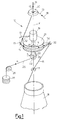
- fig. 1 is a schematic representation of the principle on which a tensioning device is based, according to the present invention, whereas fig. 1bis and 1ter show a preferential realization thereof, when the tensioning force is applied by weights;
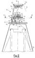
- fig. 2 is a longitudinal section of a tensioning device according to the present invention, in a first embodiment, with direct unwinding;
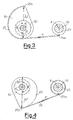
- fig. 3 is a section along the line III-III of fig. 2, with the device according to the present invention, in a first operating condition;
- fig. 4 represents the same elements of fig. 3, but in a second operating condition;
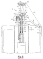
- fig. 5 is a longitudinal section of a tensioning device according to the present invention in a second embodiment, with unwinding by means of a reeling machine.
- With reference to fig. 1, a
tensioning device 10 according to the present invention, substantially comprises aradial arm 12, oscillating around a rotational axis X and including anend 13, shaped as an hook or aneyelet 15 shown in the next figures 2 and 5, for example made of ceramic or other material having a low friction coefficient, to guide ayarn 16 which is unwound from abobbin 18, coaxial to the rotational axis X. - The
radial arm 12 is fixed to anend 19 of ashaft 20 coaxial with the rotational axis X and free to rotate with respect to a windingpulley 21, also coaxial to the rotational axis X. The windingpulley 21 has a fixed radius R. - A
small pulley 23 is wedged at theother end 22 of theshaft 20, on which athin cable 25 is fixed, to enable the latter to be freely wound onto the peripheral surface of thesmall pulley 23. Thethin cable 25 can be substituted with a rope, a small belt or analogous flexible connecting body. Thesmall pulley 23 has a fixed radius b. - Moreover, according to a characteristic aspect of the present invention, a constant traction force P is applied to the
cable 25, obtained, for example, by means of aweight 26, arranged vertically, and acounter-pulley 29. - A first ceramic - or chromium-plated metal -
thread guide ring 30, is coaxially positioned with the rotational axis X, above theshaft 20, whereas a secondthread guide ring 31, again in ceramic or in a chromium-plated metal, is positioned coaxially with the rotational axis X, between theshaft 20 and thebobbin 18. - A
thread guide element 32 is fixed outside the windingpulley 21 so that it lies on a circumferential plane of the latter. - The forces operating on the oscillating
arm 12, as shown in fig. 1, are: - t1,
- which is the tension on the
thread 16 at the inlet of thehook 13 of the oscillatingarm 12, i.e. at the inlet of the latter, is oriented according to the tangent of thewinding pulley 21, and is equal to td + Δt; - t2,
- which is the tension on the
thread 16 at the outlet of thehook 13 of theoscillating arm 12, i.e. at the outlet of the latter, and oriented towards the rotational axis X and the centre of thethread guide ring 30; - P,
- which is the resisting force applied to the
cable 25. - The equilibrium with the rotation of the oscillating arm 12 (with respect to its axis X), under steady or almost steady conditions, regardless of the mechanical frictions, is
cable 25 and therefore on thesmall pulley 23, is kept constant for the whole winding angle envisaged on the windingpulley 21, t1 will tend to remain constant, as it is obliged to remain at such. - The
oscillating arm 12 will consequently rotate in one direction or another, in order to maintain the equilibrium between the unwinding tension of thethread 16 and the resisting moment P•b applied to thesmall pulley 23, so as to create, in relation to the actual unwinding tension of thebobbin 18, the amount of resisting tension Δt necessary for maintaining the inlet tension at thehook 13 constant. - If t1 is kept constant however, t2 at the outlet of the
hook 13 will also be constant, as : - α2
- is the contact angle of the
thread 16 with thehook 13 which is constant; - µ2
- is the friction coefficient between the
thread 16 and thehook 13, also constant for a giventhread 16 and a given material of thehook 13. - Furthermore, under the same conditions, the tension t3 will be constant, at the outlet of the upper
thread guide ring 30, both when thethread 16 is directed upwards, along the rotational axis X, and also when thethread 16 is directed downwards to form a possible descending balloon for a four-twisting procedure. In all cases we have: - α3 and µ3
- are the contact angle of the
thread 16 with theupper thread guide 30 and the friction coefficient between thethread 16 and theupper thread guide 30, respectively. - Tests and experiences of the Applicant have demonstrated that the
device 10 can be advantageously used at rates of at least up to 300m/min and also up to 450 m/min, with direct unwinding and at least up to 150 m/min and also up to 180m/min for unwinding with a reeling device. - In addition to stabilizing the tension of the
thread 16, thedevice 10 also allows the tension level requested by the downstream process to be regulated. By varying the value of the load P, the working tension can in fact be proportionally modified. - In practice, however, also the unwinding tension td can be increased by means of suitable braking systems, in order to obtain certain levels of working tension.
In the figures 1bis and 1ter a preferential realization of the balancing device is shown, where the tensioning force is applied by weights.
It has to be considered that thetensioning device 10 rotates together with the balloons of thethread 16, while the feed package is steady.
In the case of the four-twisting spindles, the inner of thebobbin 18 of doubled thread is available.
Frompulley 23 and through two counter-pulleys 29, thecable 25 reverts in an axial position within the spindle. Theweight 26 connected to it is so moving vertically into the tube of thebobbin 18.
According to a realization preferred by the invention, a joint 25' is interposed on thecable 25 that does not allow to transmit to theweight 26 the rotating movement that affects thetensioning device 10.
In figure 1ter, the joint 25' shown is made of a balls-bearing.
Theweights 26 are therefore on the axis of the twisting spindle and are not affected by centrifugal force.
The number of the wrapping turns of thethread 16 around thepulley 21 depends on the stroke available for the weights, while the quantity of theweights 26 depends on the size of thepulleys thread 16.
It has to be noted that with the realization of figure 1bis, the force exerted withweight 26 results constant and independent on extent of the angle α of contact betweenthread 16 andpulley 21. - As an alternative to the use of the
weight 26, the constant of the resistant force P can be obtained by the use of suitably applied springs and with systems which compensate the linear variation of the force for the variation, under operating conditions, in the length or angle of said springs. - Among the many possible solutions, one is illustrated as an example, with reference to figures 2, 3 and 4.
- In this solution of the present invention, the
cable 25 has one of its ends, 25a (fig. 3 and 4) integral with thesmall pulley 23, and anotherend 25b integral with acam 40, which can rotate on ahinge 41, parallel to the rotational axis X. Thecam 40 develops in a substantially linear mode with an angle β, passing from a radius A1 to a radius A2, and the amount of this development is substantially equal to the circumference of thepulley 23. - The head of a
spring 42 of the flexional type, with a high number of coils (20, for example) is fixed to thecam 40, and arranged coaxially with the hinge 41 (fig. 2, 3 and 4). The other end of thespring 42 is fixed to a supporting plate 45 (fig. 2) of thedevice 10. - In this solution, the
spring 42 acts on the sameradial arm 12 through thecam 40 and thesmall cable 25, which partially coils around the same and partially around thesmall pulley 23. Thecam 40, as thespring 42, when operating, linearly increases its charge, also proportionally increases the distance of thecable 25 from the axis of thehinge 41. In this way, the tension P on thecable 25 is always the same, for any angular position of thecam 40 and theradial arm 12. - If, for example, the envisaged working angle of the
radial arm 12 is 360°, the angle β of thecam 40 and therefore of thespring 42 is 180°, thespring 42 is precharged for 180°, and the radius A2 is equal to the double of the radius A1, as thespring 42 doubles its charge, thecam 40 will therefore accomplish the linear doubling of the cable distance from the axis of thehinge 41 for 180° of its development, ensuring the constancy of the charge P for the whole 360° rotation of theradial arm 12, to which an analogous rotation of thesmall shaft 20 corresponds, as shown in figures 3 and 4. - A stop pin 35 (fig. 2) is vertically placed on the upper part of the winding
pulley 21, to limit the rotation of theradial arm 12 and prevent thespring 42 to discharge over a certain value. The latter can be directly fixed on the windingpulley 21, in which case the rotation angle of theradial arm 12 can be of a maximum of 360°, or a little less, or mounted on a element which can twist for a certain arc, around the rotational axis X with respect to the windingpulley 21, in which case the rotation angle of theradial arm 12 can be over 360°. - According to the embodiment of the
device 10 shown in fig. 2, thepulley 21 is fixed to thesupport plate 45, which, in turn, is fasten to a fixedcontainment structure 46, or container, placed coaxially with thebobbin 18. Aball bearing 50 is interposed between thepulley 21 andsmall shaft 20. - Moreover, a lateral
upright element 51 is indirectly fixed to the supportingplate 45 and supports athread guide group 130, consisting of a fixedbase 52, arotating disk 53, with in between aball bearing 55. Thethread guide group 130 has the same function as thethread guide ring 30. - A
pre-charge ball 56 is placed above the secondthread guide ring 31, in order to vary the value of the unwinding tension td. - According to another embodiment shown in fig. 5, the
device 10 is mounted on a reelingmachine 60, rotating around the rotational axis X. The reelingmachine 60 includes anarm 61 equipped, at one end, with athread guide 62. - In this case, the supporting
plate 45, together with the structure mounted on it, which is analogous to that previously described with reference to fig. 2, rotates together with the reelingmachine 60 with respect to thecontainer 46 placed around thebobbin 18. - The supporting
plate 45 is integral with ashort tube 63 mounted so that can twist around a fixedpin 65, with in between theball bearing 66. - A brake of known
type 67, equipped with aweight 69 for the regulation of the unwinding tension td, is associated to theshort tube 63. - For all the above, it is clear that the method according to the present invention, for stabilizing and regulating the tension of a thread being unwound from a bobbin, envisages that an amount of tension Δt, automatically variable, is added to the thread unwinding tension td applied by a body external to the device according to the invention, so as to have, downstream the device itself, a constant tension on the thread.
- It is clear, however, that the
device 10 herein described, which has been applied, for illustrative purposes, to a four-twisting twister, can be modified and/or parts can be added to it, or can be adapted for other applications, without being excluded from the scope of the present invention. For example, the device according to the present invention can be used for other types of textile machines. - It is also clear that, even if the invention has been described making reference to specific examples, any person skilled in the field can surely found other equivalent forms of tensioning devices, all of them included within the scope of the present invention.
Claims (23)
- Method for stabilizing and regulating the tension of a thread (16) being unwound from a bobbin (18), characterized in that it envisages the addition to the unwinding tension (td), of a resistant tension (Δt) automatically variable in relation to the intensity of said unwinding tension (td) so that the tension (t2) of the thread (16) at the exit from the tensioning device (10) is substantially constant to the varying of the wrapping angle (α).
- The method according to claim 1, characterized in that said resistant tension (Δt) is generated and controlled by an arm element (12), oscillating around a rotational axis (X), suitable to make said thread (16) to wind, for a variable range (α), on a cylindrical body (21), coaxial to said rotational axis (X).
- The method according to claim 2, characterized in that said arm element (12) is subjected to the action of said unwinding tension (td) of said thread (16), increased by said resistant tension (Δt), and to the action of a contrasting force (P) which opposes said unwinding tension (td), increased by said resistant tension (Δt).
- The method according to claim 3, characterized in that said contrasting force (P) is substantially constant for the entire oscillating range of said arm element (12), around said rotational axis (X).
- The method according to claim 3 or 4, characterized in that said contrasting force (P) is generated by a weight (26).
- Method according to claim 5, characterized in that said contrasting force(P) is generated by a weight (26) placed in the proximity of the axis (X) of the twisting spindle and of the tensioning device (10).
- The method according to claim 3 or 4, characterized in that said contrasting force (P) is generated by an elastic element (42).
- The method according to one or more of claims 3 to 7, characterized in that said contrasting force (P) has a value which can be regulated.
- Tensioning device for stabilizing and regulating the tension of a thread (16) being unwound from a bobbin (18), characterized in that tensioning means (32) are envisaged to add a resistant tension (Δt) to the unwinding tension (td), such resistant tension being automatically variable in relation to the intensity of said unwinding tension (td), so that the tension (t2) of the thread (16) at the exit from the tensioning device (10) is substantially constant to the varying of the wrapping angle (α).
- The device according to claim 9, characterized in that said tensioning means include an arm element (12) suitable to oscillate around a rotation axis (X), in order to wind, for a variable range (α), said thread (16) on a cylindrical body (21) coaxial with said rotation axis (X).
- The device according to claim 9, characterized in that said arm element (12) is subject to the action of said unwinding tension (td) of said thread (16), increased by said resistant tension (Δt), and to the action of a contrasting force (P) which opposes said unwinding tension (td), increased by said resistant tension (Δt).
- The device according to claim 11, characterized in that said contrasting force (P) is substantially constant for the entire oscillation range of said arm element (12) around said rotational axis (X).
- The device according to claim 11 or 12, characterized in that said arm element (12) is integral with a cylindrical element (23) rotating around said rotational axis (X) and connected to a flexible haulage element (25) on which said contrasting force (P) is applied.
- The device according to claim 13, characterized in that said haulage element (25) includes a small cable, a rope or a small belt.
- The device according to claim 13 or 14, characterized in that said contrasting force (P) is generated by a weight (26) associated with said haulage element (25).
- Device according to claim 15, characterized in that said contrasting force (P) is generated by a weight (26) placed in correspondence with the axis (X) of the twisting spindle and of the tensioning device(10).
- Device according to claim 16, characterized in that within the haulage element (25) is inserted a joint (25') that does not transmit to the weight (26) the rotating movement that affects the tensioning device (10).
- The device according to claim 13 or 14, characterized in that said contrasting force (P) is generated by an elastic element (42) associated with said haulage element (25).
- The device according to claim 18, characterized in that said elastic element includes a spring of the flexional type (42) connected to a cam (40) rotating on an axis parallel to said rotational axis (X), a first end (25a) of said haulage element (25) being integral with said cylindrical element (23), and a second end (25b) being integral with said cam (40).
- The device according to claim 19, characterized in that said cam (40) develops in a substantially linear mode for a certain angle (β), its radius (A1-A2) progressively increasing, and the entity of its development is substantially equal to the circumference of said cylindrical element (23).
- The device according to claims 19 or 20, characterized in that said spring (42) is arranged coaxially to said cam (40) and one of its ends is fixed to said cam (40), whereas the other end is fixed to a supporting plate (45).
- The device according to claims 10 or 21, characterized in that said cylindrical body (21), on which said thread (16) is suitable for being wound, is fixed to said supporting plate (45) which is immobile with respect to said bobbin (18), in the case of direct unwinding, and rotates together with the reeling machine (60) with respect to said bobbin (18), when unwinding with a reeling machine (60).
- A method and tensioning device for stabilizing and regulating the tension of a thread (16) being unwound from a bobbin (18), substantially as described with reference to the enclosed drawings.
Applications Claiming Priority (2)
| Application Number | Priority Date | Filing Date | Title |
|---|---|---|---|
| ITUD20030143 | 2003-07-01 | ||
| IT000143A ITUD20030143A1 (en) | 2003-07-01 | 2003-07-01 | METHOD AND TENSIONING DEVICE FOR STABILIZING AND ADJUSTING THE THREAD TENSION IN A COIL WHEEL. |
Publications (3)
| Publication Number | Publication Date |
|---|---|
| EP1493856A2 true EP1493856A2 (en) | 2005-01-05 |
| EP1493856A3 EP1493856A3 (en) | 2006-03-22 |
| EP1493856B1 EP1493856B1 (en) | 2012-09-19 |
Family
ID=33428330
Family Applications (1)
| Application Number | Title | Priority Date | Filing Date |
|---|---|---|---|
| EP04076862A Expired - Lifetime EP1493856B1 (en) | 2003-07-01 | 2004-06-28 | Method and tensioning device for stabilizing and regulating the tension of thread being unwound from bobbins |
Country Status (4)
| Country | Link |
|---|---|
| US (1) | US7104483B2 (en) |
| EP (1) | EP1493856B1 (en) |
| CN (1) | CN100532231C (en) |
| IT (1) | ITUD20030143A1 (en) |
Cited By (1)
| Publication number | Priority date | Publication date | Assignee | Title |
|---|---|---|---|---|
| RU2564875C1 (en) * | 2014-04-17 | 2015-10-10 | Федеральное государственное бюджетное образовательное учреждение высшего профессионального образования "Ивановский государственный энергетический университет имени В.И. Ленина" (ИГЭУ) | Device of stabilising winding density of flexible material |
Families Citing this family (15)
| Publication number | Priority date | Publication date | Assignee | Title |
|---|---|---|---|---|
| ES2616332T3 (en) * | 2007-04-17 | 2017-06-12 | International Textile Group, Inc. | Denim fabric |
| DE102008033849A1 (en) * | 2008-07-19 | 2010-01-21 | Oerlikon Textile Gmbh & Co. Kg | Method for operating a spindle of a double-twisting or cabling machine |
| KR100944478B1 (en) * | 2009-09-07 | 2010-03-03 | 윤태증 | Unwinding apparatus |
| DE102011113614A1 (en) * | 2011-09-16 | 2013-03-21 | Oerlikon Textile Gmbh & Co. Kg | Yarn delivery |
| CN102765638A (en) * | 2012-07-19 | 2012-11-07 | 绍兴文理学院 | Adjustor capable of automatically adjusting yarn tension |
| CN103612947B (en) * | 2013-11-23 | 2017-02-15 | 金元宝弹簧设备(东莞)有限公司 | Automatic feed device for spring forming machine |
| DE102014110153A1 (en) * | 2014-07-18 | 2016-01-21 | Inotec Gmbh Maschinenentwicklung Und Vertrieb | Method for setting sausages on a sausage strand |
| CN104355184B (en) * | 2014-10-24 | 2017-03-01 | 苏州亘今纺织科技有限公司 | A kind of thread-tension on-line checking and control device |
| CN104294429B (en) * | 2014-10-24 | 2016-11-02 | 苏州亘今纺织科技有限公司 | A kind of real-time adjusting apparatus of thread-tension |
| CN104805545A (en) * | 2015-05-12 | 2015-07-29 | 安徽华茂纺织股份有限公司 | Direct spinning device for large package filament yarns for cotton spinning |
| CN107164858A (en) * | 2017-06-12 | 2017-09-15 | 湖州辰瑞纺织有限公司 | A kind of device for controlling tension of warping machine |
| CN108584545B (en) * | 2018-06-11 | 2023-11-03 | 淄博海天纺织有限公司 | Mechanical yarn bundle tension adjusting device |
| WO2022047013A1 (en) * | 2020-08-27 | 2022-03-03 | American Linc, Llc | Canister-yarn tensioning assembly incorporating a pivoted yarn tensioner |
| CN112408094B (en) * | 2020-11-18 | 2022-09-13 | 胡少坤 | Wire take-up buffer, wire take-up device and method |
| CN113026161B (en) * | 2021-03-02 | 2021-12-14 | 联亚智能科技(苏州)有限公司 | Spindle tension control device and control method of pay-off tension thereof |
Citations (3)
| Publication number | Priority date | Publication date | Assignee | Title |
|---|---|---|---|---|
| GB1038504A (en) | 1962-04-21 | 1966-08-10 | Allma Allgauer Maschb G M B H | Thread brake, in particular for double twisting spindles |
| IT1007773B (en) | 1973-04-02 | 1976-10-30 | Int Standard Electric Corp | LATCH CLOSURE RELAY WITH REED TAPS |
| EP1007773A1 (en) | 1997-06-05 | 2000-06-14 | D'Agnolo, Armando | Multiple twist spindle |
Family Cites Families (9)
| Publication number | Priority date | Publication date | Assignee | Title |
|---|---|---|---|---|
| US1620558A (en) * | 1927-03-08 | Unwinding device | ||
| US2314070A (en) * | 1940-12-10 | 1943-03-16 | Bogoslowsky Boris | Tensioning device |
| DE1184861B (en) | 1958-12-11 | 1965-01-07 | Philips Nv | Device for measuring the amplitude of voltage pulses |
| DE1188484B (en) * | 1960-05-07 | 1965-03-04 | Berliner Maschb A G Vormals L | Thread brake for two-for-one twisting spindles |
| DE1184681B (en) * | 1961-08-01 | 1964-12-31 | Barmag Barmer Maschf | Thread tensioning device for twisting two individual threads on a double wire spindle |
| US3165882A (en) * | 1962-04-21 | 1965-01-19 | Allma Allgauer Maschb G M B H | Thread brake, in particular for double twisting spindles |
| US3153894A (en) * | 1963-05-29 | 1964-10-27 | Allma Allgauer Maschb G M B H | Spool head for double twisting machines |
| FR2522698A1 (en) * | 1982-03-03 | 1983-09-09 | Verdol Sa | CORONAL WITH VARIABLE RESISTANT TORQUE |
| CN2170289Y (en) * | 1993-05-17 | 1994-06-29 | 上海铭联新技术经营公司 | Self-adjustable warp tension let-off regulating device |
-
2003
- 2003-07-01 IT IT000143A patent/ITUD20030143A1/en unknown
-
2004
- 2004-06-28 US US10/878,962 patent/US7104483B2/en not_active Expired - Fee Related
- 2004-06-28 EP EP04076862A patent/EP1493856B1/en not_active Expired - Lifetime
- 2004-07-01 CN CNB200410079406XA patent/CN100532231C/en not_active Expired - Fee Related
Patent Citations (3)
| Publication number | Priority date | Publication date | Assignee | Title |
|---|---|---|---|---|
| GB1038504A (en) | 1962-04-21 | 1966-08-10 | Allma Allgauer Maschb G M B H | Thread brake, in particular for double twisting spindles |
| IT1007773B (en) | 1973-04-02 | 1976-10-30 | Int Standard Electric Corp | LATCH CLOSURE RELAY WITH REED TAPS |
| EP1007773A1 (en) | 1997-06-05 | 2000-06-14 | D'Agnolo, Armando | Multiple twist spindle |
Cited By (1)
| Publication number | Priority date | Publication date | Assignee | Title |
|---|---|---|---|---|
| RU2564875C1 (en) * | 2014-04-17 | 2015-10-10 | Федеральное государственное бюджетное образовательное учреждение высшего профессионального образования "Ивановский государственный энергетический университет имени В.И. Ленина" (ИГЭУ) | Device of stabilising winding density of flexible material |
Also Published As
| Publication number | Publication date |
|---|---|
| ITUD20030143A1 (en) | 2005-01-02 |
| US7104483B2 (en) | 2006-09-12 |
| EP1493856A3 (en) | 2006-03-22 |
| CN100532231C (en) | 2009-08-26 |
| CN1590263A (en) | 2005-03-09 |
| EP1493856B1 (en) | 2012-09-19 |
| US20050011984A1 (en) | 2005-01-20 |
Similar Documents
| Publication | Publication Date | Title |
|---|---|---|
| US7104483B2 (en) | Method and tensioning device for stabilizing and regulating the tension of thread being unwound from bobbins | |
| US3742693A (en) | Yarn-twisting apparatus for formation of multiple-ply thread | |
| US2586037A (en) | Uniform strand tension device | |
| EP0225660B1 (en) | Method and system for spinning with a rotary balloon-checking device | |
| US2379806A (en) | Double twist twister | |
| US4469290A (en) | Thread guide for coaxially mounted bobbins | |
| US4391087A (en) | Twisting apparatus | |
| US3976261A (en) | Belt-type thread-supply apparatus | |
| US2559735A (en) | Strand twisting machine | |
| US2811013A (en) | Yarn twisting machine | |
| CN102162158A (en) | Device for automatically adjusting the tension of the feeding yarn of four-twist spindles | |
| US2613886A (en) | Strand tensioning device | |
| US2609652A (en) | Double-twist spindle | |
| US2869313A (en) | Method of and apparatus for plying strands | |
| US4487009A (en) | Spindle cap having a variable moment of resistance | |
| EP2028300A2 (en) | Device for controlling and reducing the tension pulsations in the feed of four-for-one twisting spindles | |
| US3133403A (en) | Rotatable yarn guides adapted for use on double twist spindles | |
| GB338606A (en) | Improvements in machines for spinning, doubling, twisting and the like, yarns, fibres, and the like | |
| EP2028301B1 (en) | Compensation device of the tension pulsations in four-for-one twisting spindles | |
| US2736511A (en) | Twister tension assembly | |
| US3264812A (en) | Apparatus for twisting yarn | |
| US1995041A (en) | Textile appliance | |
| US2795102A (en) | Twister spindles | |
| US2802329A (en) | Twisters | |
| SU1509330A1 (en) | Device for unwinding filament |
Legal Events
| Date | Code | Title | Description |
|---|---|---|---|
| PUAI | Public reference made under article 153(3) epc to a published international application that has entered the european phase |
Free format text: ORIGINAL CODE: 0009012 |
|
| AK | Designated contracting states |
Kind code of ref document: A2 Designated state(s): AT BE BG CH CY CZ DE DK EE ES FI FR GB GR HU IE IT LI LU MC NL PL PT RO SE SI SK TR |
|
| AX | Request for extension of the european patent |
Extension state: AL HR LT LV MK |
|
| PUAL | Search report despatched |
Free format text: ORIGINAL CODE: 0009013 |
|
| AK | Designated contracting states |
Kind code of ref document: A3 Designated state(s): AT BE BG CH CY CZ DE DK EE ES FI FR GB GR HU IE IT LI LU MC NL PL PT RO SE SI SK TR |
|
| AX | Request for extension of the european patent |
Extension state: AL HR LT LV MK |
|
| RIC1 | Information provided on ipc code assigned before grant |
Ipc: D01H 13/10 20060101ALI20060131BHEP Ipc: B65H 59/16 20060101AFI20060131BHEP |
|
| 17P | Request for examination filed |
Effective date: 20060919 |
|
| AKX | Designation fees paid |
Designated state(s): AT BE BG CH CY CZ DE DK EE ES FI FR GB GR HU IE IT LI LU MC NL PL PT RO SE SI SK TR |
|
| 17Q | First examination report despatched |
Effective date: 20091015 |
|
| REG | Reference to a national code |
Ref country code: DE Ref legal event code: R079 Ref document number: 602004039350 Country of ref document: DE Free format text: PREVIOUS MAIN CLASS: B65H0059160000 Ipc: B65H0059360000 |
|
| RIC1 | Information provided on ipc code assigned before grant |
Ipc: B65H 59/16 20060101ALI20120208BHEP Ipc: B65H 59/36 20060101AFI20120208BHEP |
|
| GRAJ | Information related to disapproval of communication of intention to grant by the applicant or resumption of examination proceedings by the epo deleted |
Free format text: ORIGINAL CODE: EPIDOSDIGR1 |
|
| GRAP | Despatch of communication of intention to grant a patent |
Free format text: ORIGINAL CODE: EPIDOSNIGR1 |
|
| RIN1 | Information on inventor provided before grant (corrected) |
Inventor name: D'AGNOLO, ARMANDO |
|
| RAP1 | Party data changed (applicant data changed or rights of an application transferred) |
Owner name: PENELOPE S.P.A. |
|
| GRAS | Grant fee paid |
Free format text: ORIGINAL CODE: EPIDOSNIGR3 |
|
| RAP1 | Party data changed (applicant data changed or rights of an application transferred) |
Owner name: SAVIO MACCHINE TESSILI S.P.A. |
|
| GRAA | (expected) grant |
Free format text: ORIGINAL CODE: 0009210 |
|
| RAP1 | Party data changed (applicant data changed or rights of an application transferred) |
Owner name: SAVIO MACCHINE TESSILI S.P.A. |
|
| AK | Designated contracting states |
Kind code of ref document: B1 Designated state(s): AT BE BG CH CY CZ DE DK EE ES FI FR GB GR HU IE IT LI LU MC NL PL PT RO SE SI SK TR |
|
| REG | Reference to a national code |
Ref country code: GB Ref legal event code: FG4D |
|
| REG | Reference to a national code |
Ref country code: CH Ref legal event code: EP |
|
| REG | Reference to a national code |
Ref country code: IE Ref legal event code: FG4D |
|
| REG | Reference to a national code |
Ref country code: AT Ref legal event code: REF Ref document number: 575902 Country of ref document: AT Kind code of ref document: T Effective date: 20121015 |
|
| REG | Reference to a national code |
Ref country code: DE Ref legal event code: R096 Ref document number: 602004039350 Country of ref document: DE Effective date: 20121115 |
|
| REG | Reference to a national code |
Ref country code: CH Ref legal event code: NV Representative=s name: PATENTANWAELTE SCHAAD, BALASS, MENZL AND PARTN, CH |
|
| PG25 | Lapsed in a contracting state [announced via postgrant information from national office to epo] |
Ref country code: CY Free format text: LAPSE BECAUSE OF FAILURE TO SUBMIT A TRANSLATION OF THE DESCRIPTION OR TO PAY THE FEE WITHIN THE PRESCRIBED TIME-LIMIT Effective date: 20120919 Ref country code: FI Free format text: LAPSE BECAUSE OF FAILURE TO SUBMIT A TRANSLATION OF THE DESCRIPTION OR TO PAY THE FEE WITHIN THE PRESCRIBED TIME-LIMIT Effective date: 20120919 |
|
| REG | Reference to a national code |
Ref country code: NL Ref legal event code: VDEP Effective date: 20120919 |
|
| REG | Reference to a national code |
Ref country code: AT Ref legal event code: MK05 Ref document number: 575902 Country of ref document: AT Kind code of ref document: T Effective date: 20120919 |
|
| PG25 | Lapsed in a contracting state [announced via postgrant information from national office to epo] |
Ref country code: SI Free format text: LAPSE BECAUSE OF FAILURE TO SUBMIT A TRANSLATION OF THE DESCRIPTION OR TO PAY THE FEE WITHIN THE PRESCRIBED TIME-LIMIT Effective date: 20120919 Ref country code: GR Free format text: LAPSE BECAUSE OF FAILURE TO SUBMIT A TRANSLATION OF THE DESCRIPTION OR TO PAY THE FEE WITHIN THE PRESCRIBED TIME-LIMIT Effective date: 20121220 Ref country code: SE Free format text: LAPSE BECAUSE OF FAILURE TO SUBMIT A TRANSLATION OF THE DESCRIPTION OR TO PAY THE FEE WITHIN THE PRESCRIBED TIME-LIMIT Effective date: 20120919 |
|
| PG25 | Lapsed in a contracting state [announced via postgrant information from national office to epo] |
Ref country code: NL Free format text: LAPSE BECAUSE OF FAILURE TO SUBMIT A TRANSLATION OF THE DESCRIPTION OR TO PAY THE FEE WITHIN THE PRESCRIBED TIME-LIMIT Effective date: 20120919 Ref country code: RO Free format text: LAPSE BECAUSE OF FAILURE TO SUBMIT A TRANSLATION OF THE DESCRIPTION OR TO PAY THE FEE WITHIN THE PRESCRIBED TIME-LIMIT Effective date: 20120919 Ref country code: EE Free format text: LAPSE BECAUSE OF FAILURE TO SUBMIT A TRANSLATION OF THE DESCRIPTION OR TO PAY THE FEE WITHIN THE PRESCRIBED TIME-LIMIT Effective date: 20120919 Ref country code: CZ Free format text: LAPSE BECAUSE OF FAILURE TO SUBMIT A TRANSLATION OF THE DESCRIPTION OR TO PAY THE FEE WITHIN THE PRESCRIBED TIME-LIMIT Effective date: 20120919 Ref country code: BE Free format text: LAPSE BECAUSE OF FAILURE TO SUBMIT A TRANSLATION OF THE DESCRIPTION OR TO PAY THE FEE WITHIN THE PRESCRIBED TIME-LIMIT Effective date: 20120919 Ref country code: ES Free format text: LAPSE BECAUSE OF FAILURE TO SUBMIT A TRANSLATION OF THE DESCRIPTION OR TO PAY THE FEE WITHIN THE PRESCRIBED TIME-LIMIT Effective date: 20121230 |
|
| PG25 | Lapsed in a contracting state [announced via postgrant information from national office to epo] |
Ref country code: PT Free format text: LAPSE BECAUSE OF FAILURE TO SUBMIT A TRANSLATION OF THE DESCRIPTION OR TO PAY THE FEE WITHIN THE PRESCRIBED TIME-LIMIT Effective date: 20130121 Ref country code: PL Free format text: LAPSE BECAUSE OF FAILURE TO SUBMIT A TRANSLATION OF THE DESCRIPTION OR TO PAY THE FEE WITHIN THE PRESCRIBED TIME-LIMIT Effective date: 20120919 Ref country code: SK Free format text: LAPSE BECAUSE OF FAILURE TO SUBMIT A TRANSLATION OF THE DESCRIPTION OR TO PAY THE FEE WITHIN THE PRESCRIBED TIME-LIMIT Effective date: 20120919 |
|
| PG25 | Lapsed in a contracting state [announced via postgrant information from national office to epo] |
Ref country code: AT Free format text: LAPSE BECAUSE OF FAILURE TO SUBMIT A TRANSLATION OF THE DESCRIPTION OR TO PAY THE FEE WITHIN THE PRESCRIBED TIME-LIMIT Effective date: 20120919 |
|
| PLBE | No opposition filed within time limit |
Free format text: ORIGINAL CODE: 0009261 |
|
| STAA | Information on the status of an ep patent application or granted ep patent |
Free format text: STATUS: NO OPPOSITION FILED WITHIN TIME LIMIT |
|
| PG25 | Lapsed in a contracting state [announced via postgrant information from national office to epo] |
Ref country code: DK Free format text: LAPSE BECAUSE OF FAILURE TO SUBMIT A TRANSLATION OF THE DESCRIPTION OR TO PAY THE FEE WITHIN THE PRESCRIBED TIME-LIMIT Effective date: 20120919 Ref country code: BG Free format text: LAPSE BECAUSE OF FAILURE TO SUBMIT A TRANSLATION OF THE DESCRIPTION OR TO PAY THE FEE WITHIN THE PRESCRIBED TIME-LIMIT Effective date: 20121219 |
|
| 26N | No opposition filed |
Effective date: 20130620 |
|
| REG | Reference to a national code |
Ref country code: DE Ref legal event code: R097 Ref document number: 602004039350 Country of ref document: DE Effective date: 20130620 |
|
| PG25 | Lapsed in a contracting state [announced via postgrant information from national office to epo] |
Ref country code: MC Free format text: LAPSE BECAUSE OF FAILURE TO SUBMIT A TRANSLATION OF THE DESCRIPTION OR TO PAY THE FEE WITHIN THE PRESCRIBED TIME-LIMIT Effective date: 20120919 |
|
| GBPC | Gb: european patent ceased through non-payment of renewal fee |
Effective date: 20130628 |
|
| REG | Reference to a national code |
Ref country code: IE Ref legal event code: MM4A |
|
| REG | Reference to a national code |
Ref country code: FR Ref legal event code: ST Effective date: 20140228 |
|
| PG25 | Lapsed in a contracting state [announced via postgrant information from national office to epo] |
Ref country code: GB Free format text: LAPSE BECAUSE OF NON-PAYMENT OF DUE FEES Effective date: 20130628 Ref country code: IE Free format text: LAPSE BECAUSE OF NON-PAYMENT OF DUE FEES Effective date: 20130628 |
|
| PG25 | Lapsed in a contracting state [announced via postgrant information from national office to epo] |
Ref country code: FR Free format text: LAPSE BECAUSE OF NON-PAYMENT OF DUE FEES Effective date: 20130701 |
|
| PGFP | Annual fee paid to national office [announced via postgrant information from national office to epo] |
Ref country code: TR Payment date: 20140623 Year of fee payment: 11 |
|
| PG25 | Lapsed in a contracting state [announced via postgrant information from national office to epo] |
Ref country code: LU Free format text: LAPSE BECAUSE OF NON-PAYMENT OF DUE FEES Effective date: 20130628 Ref country code: HU Free format text: LAPSE BECAUSE OF FAILURE TO SUBMIT A TRANSLATION OF THE DESCRIPTION OR TO PAY THE FEE WITHIN THE PRESCRIBED TIME-LIMIT; INVALID AB INITIO Effective date: 20040628 |
|
| PGFP | Annual fee paid to national office [announced via postgrant information from national office to epo] |
Ref country code: CH Payment date: 20150430 Year of fee payment: 12 |
|
| PGFP | Annual fee paid to national office [announced via postgrant information from national office to epo] |
Ref country code: IT Payment date: 20150619 Year of fee payment: 12 |
|
| PGFP | Annual fee paid to national office [announced via postgrant information from national office to epo] |
Ref country code: DE Payment date: 20150831 Year of fee payment: 12 |
|
| REG | Reference to a national code |
Ref country code: DE Ref legal event code: R119 Ref document number: 602004039350 Country of ref document: DE |
|
| REG | Reference to a national code |
Ref country code: CH Ref legal event code: PL |
|
| PG25 | Lapsed in a contracting state [announced via postgrant information from national office to epo] |
Ref country code: CH Free format text: LAPSE BECAUSE OF NON-PAYMENT OF DUE FEES Effective date: 20160630 Ref country code: DE Free format text: LAPSE BECAUSE OF NON-PAYMENT OF DUE FEES Effective date: 20170103 Ref country code: LI Free format text: LAPSE BECAUSE OF NON-PAYMENT OF DUE FEES Effective date: 20160630 |
|
| PG25 | Lapsed in a contracting state [announced via postgrant information from national office to epo] |
Ref country code: IT Free format text: LAPSE BECAUSE OF NON-PAYMENT OF DUE FEES Effective date: 20160628 |
|
| PG25 | Lapsed in a contracting state [announced via postgrant information from national office to epo] |
Ref country code: TR Free format text: LAPSE BECAUSE OF NON-PAYMENT OF DUE FEES Effective date: 20160628 |