EP1493854A1 - Process and device for producing nonwovens - Google Patents
Process and device for producing nonwovens Download PDFInfo
- Publication number
- EP1493854A1 EP1493854A1 EP04013153A EP04013153A EP1493854A1 EP 1493854 A1 EP1493854 A1 EP 1493854A1 EP 04013153 A EP04013153 A EP 04013153A EP 04013153 A EP04013153 A EP 04013153A EP 1493854 A1 EP1493854 A1 EP 1493854A1
- Authority
- EP
- European Patent Office
- Prior art keywords
- web
- screen belt
- belt
- supplied
- pile
- Prior art date
- Legal status (The legal status is an assumption and is not a legal conclusion. Google has not performed a legal analysis and makes no representation as to the accuracy of the status listed.)
- Granted
Links
Images


Classifications
-
- D—TEXTILES; PAPER
- D01—NATURAL OR MAN-MADE THREADS OR FIBRES; SPINNING
- D01G—PRELIMINARY TREATMENT OF FIBRES, e.g. FOR SPINNING
- D01G25/00—Lap-forming devices not integral with machines specified above
-
- D—TEXTILES; PAPER
- D04—BRAIDING; LACE-MAKING; KNITTING; TRIMMINGS; NON-WOVEN FABRICS
- D04H—MAKING TEXTILE FABRICS, e.g. FROM FIBRES OR FILAMENTARY MATERIAL; FABRICS MADE BY SUCH PROCESSES OR APPARATUS, e.g. FELTS, NON-WOVEN FABRICS; COTTON-WOOL; WADDING ; NON-WOVEN FABRICS FROM STAPLE FIBRES, FILAMENTS OR YARNS, BONDED WITH AT LEAST ONE WEB-LIKE MATERIAL DURING THEIR CONSOLIDATION
- D04H1/00—Non-woven fabrics formed wholly or mainly of staple fibres or like relatively short fibres
- D04H1/70—Non-woven fabrics formed wholly or mainly of staple fibres or like relatively short fibres characterised by the method of forming fleeces or layers, e.g. reorientation of fibres
- D04H1/74—Non-woven fabrics formed wholly or mainly of staple fibres or like relatively short fibres characterised by the method of forming fleeces or layers, e.g. reorientation of fibres the fibres being orientated, e.g. in parallel (anisotropic fleeces)
Definitions
- a fibrous web taken from a carding machine hereafter referred to as "batt”
- a crosslapper on a transversely to the feed direction of the fibrous web endlessly circulating support a multilayer nonwoven web, hereafter referred to as nonwoven fabric produced, which fed to a needle machine and there is solidified by needling.
- the stretching of the card web generates in this a reorientation of fibers, with the result that has the orientation of the fibers within the cross-laid nonwoven web transversely varies to the web direction, which in turn the stretch properties of the nonwoven web influenced by needling produced product.
- There are places in the finished product have track characteristics different from those of other places. In general, however, finished products are desired whose stretch characteristics the largely regardless of the stretch direction.
- the invention has for its object to provide a device and a method, with which a transversely profiled nonwoven web can be produced, the no Has fiber orientation disorders.
- the batt is formed by means of an aerodynamic pile generator.
- Aerodynamic pile generators are already known, for example, from DE 101 44 728 A1.
- the pile producer has facilities with the help of the Florabgabe in operation is changeable.
- the aerodynamic pile generator lays a batt that does not orientate has, so a random fiber pile, on an air-permeable surface from.
- DE 101 44 728 A1 is said to be, whose conveying speed can be regulated by means of a control unit become.
- the invention While aerofoil-making is commonly used to produce high basis weight webs of up to 400 g / m 2 which, because of this high basis weight, can be directly subjected to needling, water jet or thermobonding consolidation, the invention combines mechanical aerodynamic web production Web formation by crosslapping, for which purpose preferably thin webs with a basis weight of up to 20 g / m 2 down aerodynamically generated.
- the random fiber pile is thus laid in a cross-lapper to a nonwoven web.
- the special feature of the invention is that by appropriate control of Ab grind whatsoever the pad on which the pile is stored in the aerodynamic Florerzeugung, in the formed goal web thick and thin areas can be generated at regular intervals, these distances from the Spreading width depends on crosslapping. By suitable adjustment of the cross-stacking movement, it is then possible in a known manner to ensure that the thin places of the card web are deposited in the edge regions of the nonwoven web produced, so that the desired thickness profile of the nonwoven web is seen in the transverse direction.
- the cyclical change required for the particular application as described the basis weight of the aerodynamically generated card web is made by changing the speed of the air-permeable pad, preferably an endlessly circulating Sieve belt, which receives the fibers fed to it and the formed thereon card web transported away in the direction of the stacker.
- the speed of the air-permeable pad preferably an endlessly circulating Sieve belt
- the speed with which the screen belt rotates arises on the screen belt Florbahn whose basis weight inversely to the transport speed of the wire belt fluctuates. Due to the cyclic change in the transport speed of the screen belt
- a card web is produced, which has thin points, the regular distances from each other and which is suitable for the production of a profiled nonwoven web.
- the Unoriented fiber layer is in both the thick and in the thin areas of the card web available.
- the aerodynamic pile generator can be fed directly from a feeder because it is due to its design to some extent also performs the function of a roller card and in some cases the quality requirements waiving the use of a separate one Allow clutter.
- a feeder which has already been mentioned that Nonuniformities in the batt due to the effect of the crosslapper to some extent be compensated.
- special quality is important, is the aerodynamic Florerzeuger preferably supplied by a roll card with fibers. Of the Florerzeuger then delivers despite the longitudinal orientation of the fibers in the of the carding given and supplied to him cardstock a Wirrmaschineflor, because he the card pile completely dissolved in single fibers, which then aerodynamically without preferential direction on the air-permeable base are stored.
- the core assembly K in the present invention of FIG. 1, a tangled fiber file producer, comprises a Ganzstahlgarniturwalze 1, the several provided with trims Abdeckmulden 2 face each other.
- the all-steel set roller 1 rotates at high speed, according to Fig. 1 in a clockwise direction.
- the cover troughs 2 are intended to rotate during rotation the all-steel garnish roll 1 to keep the fibers on this.
- the all-steel set roller 1 is on the inlet side a pair of feed rollers 3 and 4 opposite, which also with all-steel sets are provided and between them or together with the Ganzstahlgarniturwalze 1 each form a gap at the supplied fibers of the one Roller to be handed to the other.
- the upstream of the feed rollers which in 1 is provided with the reference numeral 4, is a Flor Insertsmulde 5 opposite, the one with the circumference of the feed roller 4 in the direction of rotation of the feed roller. 4 forming narrowing gap.
- the drain side Guide roller 6 of an endlessly circulating conveyor belt 7 is arranged, which for feeding of fiber material from a feeder (not shown in Fig. 1).
- the Ganzstahlgarniturwalze 1 is in a range in the direction of rotation of this roller. 1 located between the wells 2 and the feed roller 3, a scraper 8 opposite, below which there is an endlessly circulating sieve belt 9, which has several Deflection rollers 10 and 11 is guided. Under the upper run of the sieve belt 9, the Scraper 8 faces, there is an open-topped suction box 12 which is connected to a Vacuum source (not shown) is connected. Furthermore, a baffle 13 is to be mentioned, which is located in a sector between the wells 2 and the scraper 8 and delimiting a fiber flight channel extending from the all-steel clothing roll 1 toward extends to the portion of the upper run of the screen belt 9, which extends above the suction box 12 is located. In a space below the baffle 13 and above the Siebbandes 9 is a pressure roller 14, which with the screen belt 9 a gap formed.
- the guide rollers. 6 and 10 characterized as having an individual drive means. These drive devices are connected to a control unit 15, which is shown in the drawing is indicated by corresponding connecting lines.
- one of a feeder (not shown) or a Carding (also not shown) dispensed and introduced via the feed belt 7 Fiber material in the narrowing gap between the first feed roller. 4 and the trough 5 introduced. Due to the all-steel set of feed roller 4 is the supplied fiber mass evened. It is from the first feed roller 4 of the adjacent and in the opposite direction of rotation rotating second feed roller. 3 pass and thereby evened out. From the second feed roller 3 are pass the fibers of the Ganzstahlgarniturwalze 1, which further uniformizes the pulp and isolated and the fibers with the help of the Abireers 8 aerodynamically deposits on the screen belt 9.
- the upper run of the screen belt 9 is by means of in the Suction box 12 prevailing negative pressure under suction, what the fiber deposit on the wire belt 9 favors and helps avoid flyaway.
- the fiber deposit on the screen belt 9 takes place completely undirected, i. the fibers within the formed on the wire belt 9 Flors have no preference orientation.
- the pile formed on the screen belt 9 is from Sieve belt, which revolves endlessly, transported away as a coherent card web.
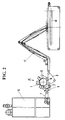
- Fig. 2 shows the application of this core unit K of FIG. 1 in an inventive Apparatus for producing a fibrous web.
- the aforementioned core unit K is located between a feeder 16 and a stacker 17, which on the screen belt 9 produced fiber web is fed.
- the stacker is designed here as a pier arm and will not be explained in detail.
- the devisrm the steep arm 17 leads above a take-off belt 18 a reciprocating motion. In the area of reversals of the laying arm of the steep arm 17, the speed of the Florabgabe must the discharge belt 18 reduced because of the necessary deceleration of devisrms to avoid unevenness of the pile storage. The transfer of fibrous web From the screen belt 9 to the steep arm 17 must therefore be adjusted accordingly.
- FIG. 3 shows a device comparable to that shown in FIG. 2, which is provided with a temporary store Z is supplemented.
- the buffer Z consists of an endlessly circulating second screen belt 19 and a storage roller 20, which is between the first wire 9 and the second screen belt 19 is arranged and stored on the first screen belt 9 card web decreases from there and deflects to the underside of the second screen belt 19, to which the Florbahn is sucked by a negative pressure, which in a between the two runs the second sieve belt 9 arranged suction box 21 prevails.
- the storage cylinder 20 is along the two sieve belts 9 and 19 movable and thus able to the length the located between the core unit K and the stacker 17 Florbahnabitess to change. An enlargement of this length causes a pile absorption, i. an intermediate storage, a reduction a corresponding Florabgabe from the Cache Z.
- the first screen belt 9 can, from the needs of a profile formation if necessary apart, be driven independently of the stacker 17.
- the embodiment of FIG. 4 differs from the embodiment of FIG. 2 in that between the feeder 16 and the core unit K a roll card W with two customers and a buffer Z are arranged.
- the roll card W has an upper pickup 22 and a lower pickup 23.
- the lower pickup 23 lays the fibrous web removed from the carding drum 24 of the roll carding W on endless circulating pile conveyor belt 25.
- the upper loader 22 also places one Fibrous on an endless circulating transfer belt 26, the latter Flor on the Flortransportband already located on the pile 25 sets, of the lower Customer 23 comes. If a higher flange thickness is desired, can on the Krempeitambour 24 also more than two customers, for example, four customers, be present.
- the invention is not limited thereto.
- the pile conveyor belt 25 is at the same time part of a buffer Z, to which a pile storage roller 20 heard between the Flortransportband 25 and the cache Z is arranged and along the Flortransportbandes 25 and the cache Z is movable.
- This storage roller 20 operates in the same manner as described with reference to Fig. 3 has been explained.
- a fiber mass fed from the reservoir 16 is separated from the roll card transformed into a uniform pile, in two layers of the upper and lower Pickups 22 and 23 removed and placed on the pile conveyor belt 25.
- the double-ply card web is fed via the temporary storage Z to the core unit K, where they in the same manner as described with reference to FIG. 1, in individual fibers is dissolved, which are stored on the screen belt 9. It can by appropriate Control the running speed of the screen belt 9 to ensure that Thick areas and thin areas are produced in the produced random fiber web.
- the fiber feed must be in the core unit K in vote be controlled with the Flor supply the Buchlegers 17. That means the feed in the core unit K must be varied in time.
- the roll card W the two card webs, which are superimposed on the pile conveyor belt 25, with constant speed and thickness. The difference between this constant Florabgabe of the roll card W and the pile recording at the core unit K is compensated by the buffer Z.
- FIGS. 2 to 4 refer to the representation of the control devices has been dispensed with for driving the various units. It should be noted that a speed modulation at the carding drum 24 and at the all-steel set roller 1 because of the large masses excreted, leaving alone the drives of feed rollers, storage roller and second screen belt 19 of the pile store into consideration come.
Abstract
Description
Bei der Herstellung von Nadelfilzen wird aus einer von einer Krempel abgenommenen Faserflorbahn, nachfolgend kurz Faserflor genannt, mit Hilfe eines Kreuzlegers auf einer quer zur Zuführrichtung des Faserflors endlos umlaufenden Unterlage eine mehrlagige Faservliesbahn, nachfolgend kurz Faservlies genannt, erzeugt, die einer Nadelmaschine zugeführt und dort durch Vernadelung verfestigt wird.In the manufacture of needle felts, a fibrous web taken from a carding machine, hereafter referred to as "batt", with the help of a crosslapper on a transversely to the feed direction of the fibrous web endlessly circulating support a multilayer nonwoven web, hereafter referred to as nonwoven fabric produced, which fed to a needle machine and there is solidified by needling.
Dabei kann man beobachten, dass selbst dann, wenn das vom Kreuzleger erzeugte Faservlies über seine gesamte Breite gleichmäßig dick ist, also an allen Stellen ein konstantes Flächengewicht hat, die von der Nadelmaschine erzeugte Filz- oder Velourbahn ein quer zu ihrer Laufrichtung ungleichmäßiges Flächengewicht hat. Ihr Randbereich ist dicker, als ihr Mittenbereich.It can be observed that even if the nonwoven produced by the stacker is uniformly thick over its entire width, so a constant at all points Basis weight has, the felt or velor web produced by the needle machine transversely to their direction uneven basis weight has. Its border area is thicker than hers Midrange.
Um diesem Effekt zu begegnen, ist aus DE 37 38 190 C2 bereits eine sogenannte Profilbildung bekannt geworden, die darin besteht, dass man mit dem Kreuzleger eine Faservliesbahn ungleichmäßigen Flächengewichts erzeugt derart, dass die Faservliesbahn in Ihren Randbereichen dünner als in ihrem Mittenbereich ist. Hierfür ist es wiederum aus DE 101 39 833 A1 und DE 201 13 467 U1 bekannt, die dem Kreuzleger zugeführte Florbahn auf ihrem Weg zwischen dem Florerzeuger und dem Kreuzleger oder, wie in DE 43 04 988 C1 beschrieben, mit Hilfe des Kreuzlegers in Abstimmung mit den Legebewegungen des Kreuzlegers, zyklisch zu verstrecken, um in ihr Dünnstellen in einem vorbestimmten, regelmäßigen Abstand zu erzeugen, die dann vom Kreuzleger in den Randbereichen der aus der Florbahn erzeugten Faservliesbahn abgelegt werden.To counteract this effect, from DE 37 38 190 C2 already a so-called profile formation become known, which consists in that one with the stacker a nonwoven web Uneven basis weight generates such that the nonwoven web in your Edge areas is thinner than in their middle area. For this it is again from DE 101 39 833 A1 and DE 201 13 467 U1 known, the Kreuzleger supplied card web on their way between the pile producer and the stacker or, as in DE 43 04 988 C1 described with the help of the Kreuzlegers in accordance with the laying movements of Kreuzlegers, cyclically stretch to in their thinning in a predetermined, regular Distance to be created, then from the stacker in the edge areas of the fibrous web produced nonwoven web are stored.
Das Strecken der Florbahn erzeugt in dieser eine Umorientierung von Fasern, was zur Folge hat, dass die Orientierung der Fasern innerhalb der kreuzgelegten Faservliesbahn quer zur Bahnrichtung variiert, was wiederum die Streckeigenschaften des aus der Faservliesbahn durch Vernadelung hergestellten Produkts beeinflusst. Es entstehen Stellen im Fertigprodukt die Streckeigenschaften aufweisen, die von denen anderer Stellen abweichen. Im Allgemeinen sind aber Fertigprodukte gewünscht, deren Streckeigenschaften die weitgehend unabhängig von der Streckrichtung sind.The stretching of the card web generates in this a reorientation of fibers, with the result that has the orientation of the fibers within the cross-laid nonwoven web transversely varies to the web direction, which in turn the stretch properties of the nonwoven web influenced by needling produced product. There are places in the finished product have track characteristics different from those of other places. In general, however, finished products are desired whose stretch characteristics the largely regardless of the stretch direction.
Aus WO 99/24650 ist bekannt geworden, die für die Profilbildung erwünschten, zyklisch, oder anders gesagt, als Rapport wiederkehrenden Dünnstellen innerhalb einer Faserflorbahn durch zyklisch ungleichmäßige Abnahme des Flors von einer den Flor herstellenden Krempel zu erzeugen. Die dazu erforderliche Technik ist sehr aufwendig und nicht bei allen Flordicken durchführbar.From WO 99/24650 has become known, the desired for the profile formation, cyclic, or in other words, as a repeat of recurring thin spots within a fibrous web by cyclically uneven removal of the pile from a pile producing the pile To create clutter. The required technology is very complicated and not at all Tile punching feasible.
Der Erfindung liegt die Aufgabe zugrunde, eine Vorrichtung und ein Verfahren anzugeben, mit der eine in Querrichtung profilierte Faservliesbahn hergestellt werden kann, die keine Störungen der Faserorientierung aufweist.The invention has for its object to provide a device and a method, with which a transversely profiled nonwoven web can be produced, the no Has fiber orientation disorders.
Diese Aufgabe wird durch die im Anspruch 1 bzw. 7 angegebenen Merkmale gelöst. Vorteilhafte
Weiterbildungen der Erfindung sind Gegenstand der Unteransprüche.This object is achieved by the features specified in
Bei der Erfindung wird der Faserflor mit Hilfe eines aerodynamischen Florerzeugers gebildet. Aerodynamische Florerzeuger sind beispielsweise aus DE 101 44 728 A1 bereits bekannt. Der Florerzeuger weist Einrichtungen auf, mit deren Hilfe die Florabgabe im Betrieb veränderbar ist. Der aerodynamische Florerzeuger legt einen Faserflor, der keine Orientierung hat, also einen Wirrfaserflor, auf eine luftdurchlässige Unterlage ab. In DE 101 44 728 A1 ist hierzu gesagt, deren Fördergeschwindigkeit könne mittels einer Steuereinheit reguliert werden.In the invention, the batt is formed by means of an aerodynamic pile generator. Aerodynamic pile generators are already known, for example, from DE 101 44 728 A1. The pile producer has facilities with the help of the Florabgabe in operation is changeable. The aerodynamic pile generator lays a batt that does not orientate has, so a random fiber pile, on an air-permeable surface from. In DE 101 44 728 A1 is said to be, whose conveying speed can be regulated by means of a control unit become.
Während die aerodynamische Florerzeugung üblicherweise dazu verwendet wird, Florbahnen hohen Flächengewichts von bis zu 400 g/m2 zu erzeugen, die aufgrund dieses hohen Flächengewichts direkt einer Verfestigung durch Nadelung, Wasserstrahlbehandlung oder Thermobonding unterworfen werden können, kombiniert die Erfindung die aerodynamische Florerzeugung mit einer mechanischen Vliesbildung durch Kreuzlegen, wozu vorzugsweise dünne Florbahnen mit einem Flächengewicht bis zu 20 g/m2 herab aerodynamisch erzeugt werden. Der Wirrfaserflor wird also in einem Kreuzleger zu einer Faservliesbahn gelegt. Durch die Vielfachtäfelung des Flors innerhalb des durch Kreuzlegen der Florbahn gebildeten Vlieses mitteln sich ungewollte Dickenschwankungen innerhalb des Flors, sofern solche überhaupt vorhanden sind, entsprechend den bei der Kreuzlegung geltenden Gesetzmäßigkeiten aus. Das Besondere bei der Erfindung ist indessen, dass durch entsprechende Steuerung der Abfördergeschwindigkeit der Unterlage, auf die der Flor bei der aerodynamischen Florerzeugung abgelegt wird, in der so gebildeten Florbahn gewollt Dick- und Dünnstellen in regelmäßigen Abständen erzeugt werden können, wobei diese Abstände von der Legebreite beim Kreuzlegen abhängt. Durch geeignete Abstimmung der Kreuzlegerbewegung ist es dann in bekannter Weise möglich, dafür zu sorgen, dass die Dünnstellen der Florbahn in den Randbereichen der erzeugten Vliesbahn abgelegt werden, so das gewünschte Dickenprofil der Vliesbahn, in Querrichtung derselben gesehen, erzielt wird.While aerofoil-making is commonly used to produce high basis weight webs of up to 400 g / m 2 which, because of this high basis weight, can be directly subjected to needling, water jet or thermobonding consolidation, the invention combines mechanical aerodynamic web production Web formation by crosslapping, for which purpose preferably thin webs with a basis weight of up to 20 g / m 2 down aerodynamically generated. The random fiber pile is thus laid in a cross-lapper to a nonwoven web. As a result of the multiple paneling of the pile within the nonwoven fabric formed by crosslapping the card web, unwanted thickness fluctuations within the pile, if any, are averaged in accordance with the laws applicable at the cross cutting. The special feature of the invention, however, is that by appropriate control of Abfördergeschwindigkeit the pad on which the pile is stored in the aerodynamic Florerzeugung, in the formed goal web thick and thin areas can be generated at regular intervals, these distances from the Spreading width depends on crosslapping. By suitable adjustment of the cross-stacking movement, it is then possible in a known manner to ensure that the thin places of the card web are deposited in the edge regions of the nonwoven web produced, so that the desired thickness profile of the nonwoven web is seen in the transverse direction.
Selbstverständlich ist es auch möglich, andere Profile zu erzeugen. Das hängt ganz vom Abstand der erzeugten Dick- und Dünnstellen in der Florbahn und der Steuerung der Legebewegung des Kreuzlegers ab.Of course it is also possible to create other profiles. That depends entirely on Distance between the thick and thin spots created in the card web and the control of the laying movement of the Kreuzlegers.
Die für die besondere Anwendung, wie geschildert, erforderliche zyklische Veränderung des Flächengewichts der aerodynamisch erzeugten Florbahn erfolgt durch Veränderung der Geschwindigkeit der luftdurchlässigen Unterlage, vorzugsweise ein endlos umlaufendes Siebband, das die auf sie zugeführten Fasern aufnimmt und die davon gebildete Florbahn in Richtung auf den Kreuzleger abtransportiert. Bei gleichmäßiger Zuführung von Fasern, d.h. gleichbleibender pro Zeiteinheit auf das Siebband zugeführter Fasermenge, und wechselnder Geschwindigkeit, mit der das Siebband umläuft, entsteht auf dem Siebband eine Florbahn, deren Flächengewicht umgekehrt zur Transportgeschwindigkeit des Siebbandes schwankt. Durch die zyklische Änderung der Transportgeschwindigkeit des Siebbandes wird somit eine Florbahn erzeugt, die Dünnstellen aufweist, die regelmäßige Abstande voneinander haben, und die für die Herstellung einer profilierten Vliesbahn geeignet ist. Die unorientierte Faserlage ist dabei sowohl in den Dick- als auch in den Dünnstellen der Florbahn vorhanden.The cyclical change required for the particular application as described the basis weight of the aerodynamically generated card web is made by changing the speed of the air-permeable pad, preferably an endlessly circulating Sieve belt, which receives the fibers fed to it and the formed thereon card web transported away in the direction of the stacker. With uniform supply of fibers, i.e. Consistent per unit of time on the screen belt supplied amount of fiber, and changing The speed with which the screen belt rotates arises on the screen belt Florbahn whose basis weight inversely to the transport speed of the wire belt fluctuates. Due to the cyclic change in the transport speed of the screen belt Thus, a card web is produced, which has thin points, the regular distances from each other and which is suitable for the production of a profiled nonwoven web. The Unoriented fiber layer is in both the thick and in the thin areas of the card web available.
Der aerodynamische Florerzeuger kann direkt von einem Speiser versorgt sein, weil er aufgrund seiner Bauart in gewissem Umfange auch die Funktion einer Walzenkrempel ausübt und in manchen Fällen die Qualitätsanforderungen den Verzicht auf den Einsatz einer gesonderten Krempel zulassen. In diesem Zusammenhang ist bereits erwähnt worden, dass Ungleichmäßigkeiten im Faserflor durch die Wirkung des Kreuzlegers in gewissem Umfange ausgeglichen werden. Wo es hingegen auf besondere Qualität ankommt, ist der aerodynamische Florerzeuger vorzugsweise von einer Walzenkrempel mit Fasern versorgt. Der Florerzeuger liefert dann trotz der Längsorientierung der Fasern in den von der Krempel abgegebenen und ihm zugeführten Krempelflor einen Wirrfaserflor, weil er den Krempelflor vollständig in Einzelfasern auflöst, die dann aerodynamisch ohne Vorzugsrichtung auf der luftdurchlässigen Unterlage abgelegt werden.The aerodynamic pile generator can be fed directly from a feeder because it is due to its design to some extent also performs the function of a roller card and in some cases the quality requirements waiving the use of a separate one Allow clutter. In this context it has already been mentioned that Nonuniformities in the batt due to the effect of the crosslapper to some extent be compensated. Where on the other hand special quality is important, is the aerodynamic Florerzeuger preferably supplied by a roll card with fibers. Of the Florerzeuger then delivers despite the longitudinal orientation of the fibers in the of the carding given and supplied to him cardstock a Wirrfaserflor, because he the card pile completely dissolved in single fibers, which then aerodynamically without preferential direction on the air-permeable base are stored.
Da die Geschwindigkeit, mit der der Kreuzleger die Faserflorbahn entgegennimmt, im allgemeinen nicht mit der Augenblicksgeschwindigkeit übereinstimmt, mit der das Siebband umläuft, kann ein Zwischenspeicher eingesetzt werden, der diese sich zeitlich ändernden Geschwindigkeitsunterschiede ausgleicht.As the speed at which the stacker receives the fibrous web, in general does not coincide with the instantaneous speed with which the screen belt can be used, a cache can be used, they change over time Compensates for speed differences.
Wenn man die Geschwindigkeiten der Speisewalze und des Siebbandes am aerodynamischen Florerzeuger in Abhängigkeit von der Legebewegung des Kreuzlegers regelt, kann auf einen Florspeicher zwischen dem Florerzeuger und dem Kreuzleger verzichtet werden, allerdings ist es dann notwendig, dass auf der Einlaufseite des Florerzeugers eine Speichereinrichtung vorhanden ist, die den Geschwindigkeitsunterschieden Rechnung trägt, mit der der Florerzeuger das von ihm zu verarbeitende Fasermaterial entgegennimmt. Ein Speiser üblicher Bauart hat solche Speichereigenschaften von Hause aus, so dass bei ihm nicht die Gefahr besteht, dass er überläuft. Eine gesonderte Zwischenspeichereinrichtung ist dann entbehrlich.If one of the speeds of the feed roller and the sieve belt at the aerodynamic Flor producers in dependence on the laying movement of the Kreuzlegers regulates can to dispense with a pile storage between the pile producer and the stacker, However, it is then necessary that on the inlet side of the pile generator, a storage device is present, which takes into account the speed differences, with the pile producer receives the fiber material to be processed by him. One Speiser common design has such storage properties of home, so that with him there is no danger of it overflowing. A separate temporary storage device is then dispensable.
Die mit der Erfindung erzielbaren Vorteile sind vielfältig. Ein wichtiger Vorteil gegenüber dem Stand der Technik besteht darin, dass ein vollkommen unorientiertes Vlies erzeugt wird, das keine durch Verzug hervorgerufenen Störstellen aufweist. Weiterhin ist die Vliesbildung auf einfachste Weise möglich. Es kann gegebenenfalls auf gesonderte Zwischenspeicher zum Ausgleich von Geschwindigkeitsunterschieden zwischen den an der Vliesbildung beteiligten Aggregaten verzichtet werden. Es kann jedes beliebige Vliesprofil in der den Kreuzleger verlassenden Faservliesbahn erzeugt werden, weil nur kleine Maschinenmassen zum Zwecke der Profilbildung gebremst und beschleunigt werden müssen. Die Massenvariation innerhalb der Faserflorbahnist größer, weil Fasermasse aufgebaut werden kann. Das ist besonders dann gut möglich, wenn keine Krempel als Speisevorrichtung für den aerodynamischen Florerzeuger verwendet wird, sondern dieser direkt aus einem Speiser versorgt wird. Ist eine Krempel als Versorger für den aerodynamischen Florerzeuger vorgesehen, kann man durch Verminderung der Transportgeschwindigkeit des Siebbandes auf diesem Fasermassen anhäufen.The achievable with the invention advantages are many. An important advantage over The prior art is that produces a completely unoriented fleece is that has no defects caused by distortion. Furthermore, the web formation in the simplest way possible. It may be available on separate buffers to compensate for differences in speed between those at the web formation participating units are dispensed with. It can be any fleece profile in the the crosslapper leaving nonwoven web are generated because only small machine masses for the purpose of profiling must be slowed down and accelerated. The Mass variation within the fiber web is greater because fiber mass is built up can. This is especially possible if no clutter as a feeding device for the aerodynamic pile generator is used, but this directly from a feeder is supplied. Is a clutter as a provider for the aerodynamic pile producer provided, one can by reducing the transport speed of the screen belt pile on this pulp.
Die Erfindung wird nachfolgend unter Bezugnahme auf in den Zeichnungen dargestellte Ausführungsbeispiele näher erläutert. Es zeigt:
- Fig. 1
- die Kernbaugruppe der vorliegenden Erfindung mit Ganzstahlgarniturwalze, Faserzuführeinrichtung und Siebband;
- Fig. 2
- eine Vorrichtung gemäß der Erfindung mit der Kernbaugruppe von Fig. 1, einem Speiser stromaufwärts und einem Kreuzleger stromabwärts davon;
- Fig. 3
- eine weitere Vorrichtung gemäß der Erfindung mit der Kernbaugruppe von Fig. 1, einem Speiser stromaufwärts und einem Zwischenspeicher sowie einem Kreuzleger stromabwärts davon, und
- Fig. 4
- eine weitere Vorrichtung gemäß der Erfindung mit der Kernbaugruppe von Fig. 1, einem Speiser und einer Walzenkrempelanordnung stromaufwärts sowie einem Florspeicher und einem Kreuzleger stromabwärts davon.
- Fig. 1
- the core assembly of the present invention with all-steel garnish roll, fiber feeder and screen belt;
- Fig. 2
- a device according to the invention with the core assembly of Figure 1, a feeder upstream and a stacker downstream thereof;
- Fig. 3
- a further device according to the invention with the core assembly of Figure 1, a feeder upstream and a buffer and a stacker downstream thereof, and
- Fig. 4
- a further device according to the invention with the core assembly of Fig. 1, a feeder and a roll carding arrangement upstream and a pile store and a stacker downstream thereof.
Die Kernbaugruppe K in der vorliegenden Erfindung nach Fig. 1, ein Wirrfaserflorerzeuger,
umfasst eine Ganzstahlgarniturwalze 1, der mehrere mit Garnituren versehene Abdeckmulden
2 gegenüberstehen. Die Ganzstahlgarniturwalze 1 rotiert mit hoher Drehzahl, gemäß
Fig. 1 im Uhrzeigersinn. Die Abdeckmulden 2 sind dazu bestimmt, während der Rotation
der Ganzstahlgarniturwalze 1 die Fasern auf dieser zu halten. Der Ganzstahlgarniturwalze
1 steht einlaufseitig ein Speisewalzenpaar 3 und 4 gegenüber, die gleichfalls mit Ganzstahlgarnituren
versehen sind und die zwischen sich bzw. zusammen mit der Ganzstahlgarniturwalze
1 jeweils einen Spalt ausbilden, an dem zugeführte Fasern von der einen
Walze an die andere übergeben werden. Der stromaufwärtigen der Speisewalzen, die in
Fig. 1 mit dem Bezugszeichen 4 versehen ist, steht eine Florführungsmulde 5 gegenüber,
die mit dem Umfang der Speisewalze 4 einen sich in Umlaufrichtung der Speisewalze 4
verengenden Spalt ausbildet. Am Ende größerer Breite dieses Spaltes ist die ablaufseitige
Umlenkwalze 6 eines endlos umlaufenden Zuführbandes 7 angeordnet, das zur Zuführung
von Fasermaterial von einem Speiser (in Fig. 1 nicht dargestellt) bestimmt ist.The core assembly K in the present invention of FIG. 1, a tangled fiber file producer,
comprises a Ganzstahlgarniturwalze 1, the several provided with trims Abdeckmulden
2 face each other. The all-steel set roller 1 rotates at high speed, according to
Fig. 1 in a clockwise direction. The
Der Ganzstahlgarniturwalze 1 steht in einem Bereich, der in Umlaufrichtung dieser Walze 1
zwischen den Mulden 2 und der Speisewalze 3 gelegen ist, ein Abstreifer 8 gegenüber,
unterhalb dessen sich ein endlos umlaufendes Siebband 9 befindet, das über mehrere
Umlenkwalzen 10 und 11 geführt ist. Unter dem oberen Trum des Siebbandes 9, das dem
Abstreifer 8 gegenübersteht, befindet sich ein oben offener Saugkasten 12, der an eine
Unterdruckquelle (nicht dargestellt) angeschlossen ist. Weiterhin ist ein Leitblech 13 zu erwähnen,
das sich in einem Sektor zwischen den Mulden 2 und dem Abstreifer 8 befindet
und einen Faserflugkanal begrenzt, der sich von der Ganzstahlgarniturwalze 1 in Richtung
auf den Abschnitt des oberen Trums des Siebbandes 9 erstreckt, der sich über dem Saugkasten
12 befindet. In einem Zwischenraum unterhalb des Leitblechs 13 und oberhalb des
Siebbandes 9 befindet sich eine Andruckwalze 14, die mit dem Siebband 9 einen Spalt
ausbildet.The Ganzstahlgarniturwalze 1 is in a range in the direction of rotation of this roller. 1
located between the
Durch entsprechende Markierung in Sektoren sind in der Zeichnung die Umlenkwalzen 6
und 10 als solche gekennzeichnet, die über eine individuelle Antriebseinrichtung verfügen.
Diese Antriebseinrichtungen sind mit einem Steuergerät 15 verbunden, was in der Zeichnung
durch entsprechende Verbindungsleitungen angedeutet ist.By appropriate marking in sectors are in the drawing, the guide rollers. 6
and 10 characterized as having an individual drive means.
These drive devices are connected to a
Im Betrieb dieser Einrichtung wird ein von einem Speiser (nicht dargestellt) oder einer
Krempel (gleichfalls nicht dargestellt) abgegebenes und über das Zuführband 7 herangeführtes
Fasermaterial in den sich verengenden Spalt zwischen der ersten Speisewalze 4
und der Mulde 5 eingeleitet. Aufgrund der Ganzstahlgarnitur der Speisewalze 4 wird die
zugeführte Fasermasse vergleichmäßigt. Sie wird von der ersten Speisewalze 4 der benachbarten
und in entgegengesetzter Drehrichtung rotierenden zweiten Speisewalze 3
übergeben und dabei nochmals vergleichmäßigt. Von der zweiten Speisewalze 3 werden
die Fasern der Ganzstahlgarniturwalze 1 übergeben, die die Fasermasse weiter vergleichmäßigt
und vereinzelt und die Fasern unter Zuhilfenahme des Abstreiters 8 aerodynamisch
auf dem Siebband 9 ablegt. Das obere Trum des Siebbandes 9 ist mittels des in dem
Saugkasten 12 herrschenden Unterdrucks untersaugt, was die Faserablage auf dem Siebband
9 begünstigt und Faserflug vermeiden hilft. Die Faserablage auf dem Siebband 9 erfolgt
vollkommen ungerichtet, d.h. die Fasern innerhalb des auf dem Siebband 9 gebildeten
Flors haben keine Vorzugsorientierung. Der auf dem Siebband 9 gebildete Flor wird vom
Siebband, das endlos umläuft, als zusammenhängende Florbahn abtransportiert.In operation of this device, one of a feeder (not shown) or a
Carding (also not shown) dispensed and introduced via the
Wenn die Fasern vom Zuführband 7 mit gleichförmiger Geschwindigkeit zugeführt werden,
ist auch mit einer gleichförmigen Abgabe der von der Ganzstahlgarniturwalze 1 vereinzelten
Fasern auf dem Siebband 9 zu rechnen. Wenn dann die Transportgeschwindigkeit des
Siebbandes 9 verändert wird, ergibt sich eine Veränderung der Dicke der auf dem Siebband
9 aerodynamisch abgelegten Faserschicht. Mit Hilfe der Steuereinrichtung 15 und der
von dieser beeinflussten Laufgeschwindigkeit des Siebbandes 9 lassen sich somit in der
auf dem Siebband 9 gebildeten Faserflorbahn dicke und dünne Stellen erzeugen.When the fibers are fed from the
Fig. 2 zeigt die Anwendung dieser Kerneinheit K nach Fig. 1 in einer erfindungsgemäßen
Vorrichtung zur Herstellung eines Faservlieses. Die vorgenannte Kerneinheit K befindet
sich zwischen einem Speiser 16 und einem Kreuzleger 17, dem die auf dem Siebband 9
erzeugte Faserflorbahn zugeführt wird. Der Kreuzleger ist hier als Steilarmleger ausgebildet
und soll nicht näher erläutert werden. Der Legearm des Steilarmlegers 17 führt oberhalb
eines Abzugsbandes 18 eine hin- und hergehende Bewegung aus. Im Bereich der Umkehrstellen
des Legearms des Steilarmlegers 17 muss die Geschwindigkeit der Florabgabe auf
das Abzugsband 18 wegen der notwendigen Abbremsung des Legearms herabgesetzt
werden, um Ungleichmäßigkeiten der Florablage zu vermeiden. Die Übergabe von Faserflor
vom Siebband 9 an den Steilarmleger 17 muss daher entsprechend angepasst werden.
Dieses kann im vorliegenden Falle nur durch Veränderung der Transportgeschwindigkeit
des Siebbandes 9 erfolgen, da ein Verzug des Faserflors im Übergabebereich zwischen
dem Siebband 9 und dem Steilarmleger 17 vermieden werden muss. Um nun unerwünschte
Schwankungen der Dicke des auf dem Siebband 9 abgelegten Flors zu vermeiden,
muss die Einspeisung von Fasern in die Kerneinheit K entsprechend variiert werden.
Dieses erfolgt mit Hilfe der Speisewalzen 3 und 4. Dem sich daraus ergebenden ungleichmäßigen
Faserbedarf der Kerneinheit K wird durch das dem Speiser 16 von Hause aus
innewohnende Speichervermögen Rechnung getragen. Die notwendige Abstimmung der
Bewegungsgeschwindigkeit des Siebbandes 9 mit den Legebewegungen des Kreuzlegers
17 besorgt die Steuereinrichtung 15.Fig. 2 shows the application of this core unit K of FIG. 1 in an inventive
Apparatus for producing a fibrous web. The aforementioned core unit K is located
between a
Es versteht sich, dass die Legebewegung des Legearms des Kreuzlegers mit der Zuführung der Florbahn unter Berücksichtigung von der Lage der in ihr enthaltenen Dick- und Dünnstellen abgestimmt werden muss, wenn ein bestimmtes Querprofil der gelegten Vliesbahn erzielt werden soll. Die hierfür notwendigen Einrichtungen sind bekannt und brauchen daher hier nicht erläutert zu werden.It is understood that the laying motion of the laying arm of the stacker with the feeder the card web, taking into account the location of the thick and Thin points must be matched if a particular cross-section of the laid nonwoven web should be achieved. The necessary facilities are known and need therefore not to be explained here.
Fig. 3 zeigt eine der Fig. 2 vergleichbare Vorrichtung, die um einen Zwischenspeicher Z
ergänzt ist. Der Zwischenspeicher Z besteht aus einem endlos umlaufenden zweiten Siebband
19 und einer Florspeicherwalze 20, die zwischen dem ersten Siebband 9 und dem
zweiten Siebband 19 angeordnet ist und die auf das erste Siebband 9 abgelegte Florbahn
von dort abnimmt und an die Unterseite des zweiten Siebbandes 19 umlenkt, an das die
Florbahn durch einen Unterdruck angesaugt wird, der in einem zwischen den beiden Trums
des zweiten Siebbandes 9 angeordneten Saugkasten 21 herrscht. Die Florspeicherwalze
20 ist längs der beiden Siebbänder 9 und 19 beweglich und somit in der Lage, die Länge
des zwischen der Kerneinheit K und dem Kreuzleger 17 befindlichen Florbahnabschnitts zu
verändern. Eine Vergrößerung dieses Längenabschnitts bewirkt eine Floraufnahme, d.h.
eine Zwischenspeicherung, eine Verkleinerung eine entsprechende Florabgabe aus dem
Zwischenspeicher Z.FIG. 3 shows a device comparable to that shown in FIG. 2, which is provided with a temporary store Z
is supplemented. The buffer Z consists of an endlessly circulating
Mit Hilfe des Zwischenspeichers Z lassen sich die vom Kreuzleger 17 verursachten Geschwindigkeitsänderungen
beim Einlauf der Florbahn in den Kreuzleger 17 ausgleichen,
ohne dass an der Florabgabe der Kerneinheit K auf das erste Siebband 9 etwas geändert
werden muss. Das erste Siebband 9 kann, von den Notwendigkeiten einer Profilbildung ggf.
abgesehen, unabhängig von dem Kreuzleger 17 angetrieben werden.With the help of the buffer Z can be caused by the
Die Ausführungsform von Fig. 4 unterscheidet sich von der Ausführungsform nach Fig. 2
dadurch, dass zwischen dem Speiser 16 und der Kerneinheit K eine Walzenkrempel W mit
zwei Abnehmern und ein Zwischenspeicher Z angeordnet sind. Die Walzenkrempel W hat
einen oberen Abnehmer 22 und einen unteren Abnehmer 23. Der untere Abnehmer 23 legt
den von dem Krempeltambour 24 der Walzenkrempel W abgenommenen Faserflor auf ein
endlos umlaufendes Flortransportband 25. Der obere Abnehmer 22 legt ebenfalls einen
Faserflor auf ein endlos umlaufendes Übertragungsband 26, das den letztgenannten Flor
auf den auf dem Flortransportband 25 bereits befindlichen Flor legt, der von dem unteren
Abnehmer 23 stammt. Falls eine höhere Flordicke erwünscht ist, Können an dem Krempeitambour
24 auch mehr als zwei Abnehmer, beispielsweise vier Abnehmer, vorhanden sein.
Die Erfindung ist hierauf nicht beschränkt.The embodiment of FIG. 4 differs from the embodiment of FIG. 2
in that between the
Das Flortransportband 25 ist zugleich Teil eines Zwischenspeichers Z, zu dem eine Florspeicherwalze
20 gehört, die zwischen dem Flortransportband 25 und dem Zwischenspeicher
Z angeordnet ist und längs des Flortransportbandes 25 sowie des Zwischenspeichers
Z beweglich ist. Diese Speicherwalze 20 arbeitet in der gleichen Weise, wie sie anhand der
Fig. 3 erläutert worden ist.The
Ablaufseitig des Zwischenspeichers Z befindet sich das Zuführband 7, das die auf ihm liegende
Florbahn der Kerneinheit K zuführt. Die übrigen Elemente dieser Anordnung sind
vergleichbar denen in den vorangehend beschriebenen Ausführungsformen.Expiration of the buffer Z is the
Im Betrieb wird eine aus dem Speicher 16 zugeführte Fasermasse von der Walzenkrempel
in einen gleichmäßigen Flor umgewandelt, der in zwei Lagen von den oberen und unteren
Abnehmern 22 und 23 abgenommen und auf das Flortransportband 25 gelegt wird. Von
dort wird die doppellagige Florbahn über den Zwischenspeicher Z der Kerneineinheit K zugeführt,
wo sie in derselben Weise, wie anhand von Fig. 1 beschrieben, in Einzelfasern
aufgelöst wird, die auf dem Siebband 9 abgelegt werden. Dabei kann durch entsprechende
Steuerung der Laufgeschwindigkeit des Siebbandes 9 dafür Sorge getragen werden, dass
in der erzeugten Wirrfaserflorbahn Dick- und Dünnstellen erzeugt werden. Da zwischen der
die Florbahn erzeugende Kerneinheit K und dem Kreuzleger 17 kein Zwischenspeicher
vorhanden ist, andererseits aber der Kreuzleger aus den erwähnten Gründen einen zeitlich
schwankenden Florbedarf hat, muss die Fasereinspeisung in die Kerneinheit K in Abstimmung
mit dem Florbedarf des Kreuzlegers 17 gesteuert werden. Das bedeutet, die Einspeisung
in die Kerneinheit K muss zeitlich variiert werden. Andererseits gibt die Walzenkrempel
W die beiden Florbahnen, die auf dem Flortransportband 25 übereinandergelegt werden,
mit konstanter Geschwindigkeit und Dicke ab. Der Unterschied zwischen dieser konstanten
Florabgabe von der Walzenkrempel W und der Floraufnahme an der Kerneinheit K
wird durch den Zwischenspeicher Z ausgeglichen.In operation, a fiber mass fed from the
In den Fig. 2 bis 4 ist aus Übersichtlichkeitsgründen auf die Darstellung der Steuereinrichtungen
für den Antrieb der verschiedenen Einheiten verzichtet worden. Es sei nur angemerkt,
dass eine Geschwindigkeitsmodulation am Krempeltambour 24 und an der Ganzstahlgarniturwalze
1 wegen der großen Massen ausscheidet, so dass allein die Antriebe
von Speisewalzen, Florspeicherwalze und zweitem Siebband 19 des Florspeichers in Betracht
kommen.For the sake of clarity, FIGS. 2 to 4 refer to the representation of the control devices
has been dispensed with for driving the various units. It should be noted
that a speed modulation at the carding drum 24 and at the all-steel set roller
1 because of the large masses excreted, leaving alone the drives
of feed rollers, storage roller and
Claims (7)
Applications Claiming Priority (2)
| Application Number | Priority Date | Filing Date | Title |
|---|---|---|---|
| DE10329648A DE10329648B4 (en) | 2003-07-01 | 2003-07-01 | Device for web formation |
| DE10329648 | 2003-07-01 |
Publications (2)
| Publication Number | Publication Date |
|---|---|
| EP1493854A1 true EP1493854A1 (en) | 2005-01-05 |
| EP1493854B1 EP1493854B1 (en) | 2006-03-22 |
Family
ID=33426808
Family Applications (1)
| Application Number | Title | Priority Date | Filing Date |
|---|---|---|---|
| EP04013153A Expired - Fee Related EP1493854B1 (en) | 2003-07-01 | 2004-06-03 | Process and device for producing nonwovens |
Country Status (3)
| Country | Link |
|---|---|
| EP (1) | EP1493854B1 (en) |
| AT (1) | ATE321159T1 (en) |
| DE (2) | DE10329648B4 (en) |
Cited By (4)
| Publication number | Priority date | Publication date | Assignee | Title |
|---|---|---|---|---|
| DE202014100908U1 (en) * | 2014-02-27 | 2015-05-28 | Autefa Solutions Germany Gmbh | carding |
| CN106894117A (en) * | 2017-05-06 | 2017-06-27 | 青岛源泉机械有限公司 | It is capable of the square motion comb of self-feeding |
| EP3450603A1 (en) * | 2017-09-01 | 2019-03-06 | Oskar Dilo Maschinenfabrik KG | Method for forming a profiled non-woven fabric |
| US11519111B2 (en) | 2019-08-07 | 2022-12-06 | Hubert Hergeth | Method and apparatus for forming a fiber nonwoven |
Families Citing this family (6)
| Publication number | Priority date | Publication date | Assignee | Title |
|---|---|---|---|---|
| DE202009012819U1 (en) | 2009-09-24 | 2011-02-10 | Matecs Sp. Z.O.O. | Plant for the production of fiber fleece mats and fiber fleece produced therewith |
| DE102010034777A1 (en) * | 2010-08-18 | 2012-02-23 | Hubert Hergeth | Nonwoven laying machine and method for laying a nonwoven |
| CN102953233B (en) | 2011-08-24 | 2019-01-08 | 休伯特·赫格思 | By the device of scraper |
| DE102015014301A1 (en) * | 2015-11-06 | 2017-05-11 | Hubert Hergeth | Saugsammelband |
| DE102017006235A1 (en) * | 2017-07-03 | 2019-01-03 | Hubert Hergeth | Dual fleece formation |
| DE102021000424A1 (en) | 2021-01-28 | 2022-07-28 | Hubert Hergeth | pressure roller |
Citations (6)
| Publication number | Priority date | Publication date | Assignee | Title |
|---|---|---|---|---|
| US5060347A (en) * | 1988-11-30 | 1991-10-29 | S.A. Des Ateliers Houget Duesberg Bosson | Process and device for the manufacture of non-woven fabrics |
| DE4304988C1 (en) * | 1993-02-18 | 1994-04-07 | Autefa Maschinenfab | Wadding prodn. machinery - has mechanism to extend or condense the web of gauze |
| US5353477A (en) * | 1990-03-30 | 1994-10-11 | Hergeth Hollingsworth Gmbh | Process for laying a nonwoven or the like, and nonwoven laying device |
| DE19527416A1 (en) * | 1995-07-27 | 1997-01-30 | Autefa Maschinenfab | Nonwoven produced by repeated cross-laying of carded webs - has web edges thinned by varying the laying width to improve final web uniformity |
| US6434795B1 (en) * | 1999-06-01 | 2002-08-20 | Asselin | Method for controlling the profile of a non-woven lap and related production installation |
| WO2002101130A1 (en) * | 2001-04-23 | 2002-12-19 | Autefa Automation Gmbh | Method for profiling a nonwoven fabric and profile forming device |
Family Cites Families (5)
| Publication number | Priority date | Publication date | Assignee | Title |
|---|---|---|---|---|
| DE3738190C2 (en) * | 1987-11-10 | 1997-10-16 | Autefa Holding Gmbh | Process for forming a nonwoven and nonwoven tape layer |
| FR2770855B1 (en) * | 1997-11-07 | 2000-01-28 | Asselin | METHOD AND DEVICE FOR PRODUCING A TEXTILE TABLECLOTH |
| DE10144728A1 (en) * | 2001-06-27 | 2003-01-16 | Ake Innotech Gmbh Automatisier | Twin-head aerodynamic web laying machine for producing mixed fiber webs involves two machines back to back with full spatial adjustment |
| DE20113467U1 (en) * | 2001-08-14 | 2002-12-19 | Dilo Kg Maschf Oskar | Drafting device and device for producing a nonwoven fabric |
| DE10139833A1 (en) * | 2001-08-14 | 2003-02-27 | Dilo Kg Maschf Oskar | Method and device for producing a nonwoven fabric |
-
2003
- 2003-07-01 DE DE10329648A patent/DE10329648B4/en not_active Expired - Fee Related
-
2004
- 2004-06-03 DE DE502004000367T patent/DE502004000367D1/en active Active
- 2004-06-03 EP EP04013153A patent/EP1493854B1/en not_active Expired - Fee Related
- 2004-06-03 AT AT04013153T patent/ATE321159T1/en active
Patent Citations (6)
| Publication number | Priority date | Publication date | Assignee | Title |
|---|---|---|---|---|
| US5060347A (en) * | 1988-11-30 | 1991-10-29 | S.A. Des Ateliers Houget Duesberg Bosson | Process and device for the manufacture of non-woven fabrics |
| US5353477A (en) * | 1990-03-30 | 1994-10-11 | Hergeth Hollingsworth Gmbh | Process for laying a nonwoven or the like, and nonwoven laying device |
| DE4304988C1 (en) * | 1993-02-18 | 1994-04-07 | Autefa Maschinenfab | Wadding prodn. machinery - has mechanism to extend or condense the web of gauze |
| DE19527416A1 (en) * | 1995-07-27 | 1997-01-30 | Autefa Maschinenfab | Nonwoven produced by repeated cross-laying of carded webs - has web edges thinned by varying the laying width to improve final web uniformity |
| US6434795B1 (en) * | 1999-06-01 | 2002-08-20 | Asselin | Method for controlling the profile of a non-woven lap and related production installation |
| WO2002101130A1 (en) * | 2001-04-23 | 2002-12-19 | Autefa Automation Gmbh | Method for profiling a nonwoven fabric and profile forming device |
Cited By (5)
| Publication number | Priority date | Publication date | Assignee | Title |
|---|---|---|---|---|
| DE202014100908U1 (en) * | 2014-02-27 | 2015-05-28 | Autefa Solutions Germany Gmbh | carding |
| US10443155B2 (en) | 2014-02-27 | 2019-10-15 | Autefa Solutions Germany Gmbh | Carding apparatus and carding method |
| CN106894117A (en) * | 2017-05-06 | 2017-06-27 | 青岛源泉机械有限公司 | It is capable of the square motion comb of self-feeding |
| EP3450603A1 (en) * | 2017-09-01 | 2019-03-06 | Oskar Dilo Maschinenfabrik KG | Method for forming a profiled non-woven fabric |
| US11519111B2 (en) | 2019-08-07 | 2022-12-06 | Hubert Hergeth | Method and apparatus for forming a fiber nonwoven |
Also Published As
| Publication number | Publication date |
|---|---|
| DE10329648A1 (en) | 2005-01-27 |
| ATE321159T1 (en) | 2006-04-15 |
| DE502004000367D1 (en) | 2006-05-11 |
| EP1493854B1 (en) | 2006-03-22 |
| DE10329648B4 (en) | 2005-06-16 |
Similar Documents
| Publication | Publication Date | Title |
|---|---|---|
| EP2695976B1 (en) | Supply device for delivering opened fibres or flocked fibres to a transport device | |
| EP2630287B1 (en) | Method and apparatus for producing a composite nonwoven | |
| EP0013902B1 (en) | Process and apparatus for the manufacture of velvet needle-felted webs | |
| EP1947223B1 (en) | Device for the guided transport of a web | |
| EP1285982B1 (en) | Process and apparatus for producing a fibre web | |
| EP3118361B1 (en) | Installation and method for making a multi-layer nonwoven fabric from at least one loose fibre web | |
| EP1643022B1 (en) | Method for profiling a nonwoven fabric and profile forming device | |
| EP1493854B1 (en) | Process and device for producing nonwovens | |
| EP3110997B1 (en) | Carding apparatus and carding method | |
| EP1644565B1 (en) | Method for reinforcing a web of nonwoven fabric by means of needling | |
| EP3061855B1 (en) | Roller card and method for fixing at least one fibre web | |
| DE69609171T3 (en) | DEVICE AND DEVICE FOR THE PRODUCTION OF FILES | |
| AT501434B1 (en) | VLIESZUFÜHRVORRICHTUNG | |
| AT501195B1 (en) | STEILARM VLIESLEGER AND DEVICE FOR PRODUCING A CROSS-LINKED FIBER CLOSURE | |
| WO2015067627A2 (en) | Nonwoven laying apparatus, and nonwoven laying method | |
| AT6279U1 (en) | STRETCHER AND DEVICE FOR PRODUCING A FIBER FLEECE | |
| DE202022106415U1 (en) | Fiber treatment plant | |
| DE4234354A1 (en) | Mfg. felt of great width with longitudinal fibres - using stable fibre web of comparatively small width, which is transported continuously and deposited into several layers laying on top of each other | |
| EP2635729B1 (en) | Nonwoven web laying device and method for forming a nonwoven fabric | |
| EP4087967A1 (en) | Method for producing a composite nonwoven fabric and device for producing a composite nonwoven fabric | |
| EP3260583A1 (en) | Web forming machine |
Legal Events
| Date | Code | Title | Description |
|---|---|---|---|
| PUAI | Public reference made under article 153(3) epc to a published international application that has entered the european phase |
Free format text: ORIGINAL CODE: 0009012 |
|
| 17P | Request for examination filed |
Effective date: 20041104 |
|
| AK | Designated contracting states |
Kind code of ref document: A1 Designated state(s): AT BE BG CH CY CZ DE DK EE ES FI FR GB GR HU IE IT LI LU MC NL PL PT RO SE SI SK TR |
|
| AX | Request for extension of the european patent |
Extension state: AL HR LT LV MK |
|
| AKX | Designation fees paid |
Designated state(s): AT DE FR IT |
|
| GRAP | Despatch of communication of intention to grant a patent |
Free format text: ORIGINAL CODE: EPIDOSNIGR1 |
|
| GRAS | Grant fee paid |
Free format text: ORIGINAL CODE: EPIDOSNIGR3 |
|
| GRAA | (expected) grant |
Free format text: ORIGINAL CODE: 0009210 |
|
| AK | Designated contracting states |
Kind code of ref document: B1 Designated state(s): AT DE FR IT |
|
| REF | Corresponds to: |
Ref document number: 502004000367 Country of ref document: DE Date of ref document: 20060511 Kind code of ref document: P |
|
| ET | Fr: translation filed | ||
| PLBE | No opposition filed within time limit |
Free format text: ORIGINAL CODE: 0009261 |
|
| STAA | Information on the status of an ep patent application or granted ep patent |
Free format text: STATUS: NO OPPOSITION FILED WITHIN TIME LIMIT |
|
| 26N | No opposition filed |
Effective date: 20061227 |
|
| REG | Reference to a national code |
Ref country code: FR Ref legal event code: PLFP Year of fee payment: 13 |
|
| PGFP | Annual fee paid to national office [announced via postgrant information from national office to epo] |
Ref country code: FR Payment date: 20160623 Year of fee payment: 13 Ref country code: AT Payment date: 20160628 Year of fee payment: 13 |
|
| PGFP | Annual fee paid to national office [announced via postgrant information from national office to epo] |
Ref country code: DE Payment date: 20160628 Year of fee payment: 13 Ref country code: IT Payment date: 20160630 Year of fee payment: 13 |
|
| REG | Reference to a national code |
Ref country code: DE Ref legal event code: R119 Ref document number: 502004000367 Country of ref document: DE |
|
| REG | Reference to a national code |
Ref country code: AT Ref legal event code: MM01 Ref document number: 321159 Country of ref document: AT Kind code of ref document: T Effective date: 20170603 |
|
| REG | Reference to a national code |
Ref country code: FR Ref legal event code: ST Effective date: 20180228 |
|
| PG25 | Lapsed in a contracting state [announced via postgrant information from national office to epo] |
Ref country code: DE Free format text: LAPSE BECAUSE OF NON-PAYMENT OF DUE FEES Effective date: 20180103 |
|
| PG25 | Lapsed in a contracting state [announced via postgrant information from national office to epo] |
Ref country code: IT Free format text: LAPSE BECAUSE OF NON-PAYMENT OF DUE FEES Effective date: 20170603 Ref country code: FR Free format text: LAPSE BECAUSE OF NON-PAYMENT OF DUE FEES Effective date: 20170630 Ref country code: AT Free format text: LAPSE BECAUSE OF NON-PAYMENT OF DUE FEES Effective date: 20170603 |