EP1493549A2 - Verfahren und Vorrichtung zur Herstellung eines Faserverbundwerkstoff-Bauteils - Google Patents
Verfahren und Vorrichtung zur Herstellung eines Faserverbundwerkstoff-Bauteils Download PDFInfo
- Publication number
- EP1493549A2 EP1493549A2 EP04015030A EP04015030A EP1493549A2 EP 1493549 A2 EP1493549 A2 EP 1493549A2 EP 04015030 A EP04015030 A EP 04015030A EP 04015030 A EP04015030 A EP 04015030A EP 1493549 A2 EP1493549 A2 EP 1493549A2
- Authority
- EP
- European Patent Office
- Prior art keywords
- component
- hydrostatic pressure
- matrix material
- pressure
- preform
- Prior art date
- Legal status (The legal status is an assumption and is not a legal conclusion. Google has not performed a legal analysis and makes no representation as to the accuracy of the status listed.)
- Withdrawn
Links
Images


Classifications
-
- B—PERFORMING OPERATIONS; TRANSPORTING
- B30—PRESSES
- B30B—PRESSES IN GENERAL
- B30B15/00—Details of, or accessories for, presses; Auxiliary measures in connection with pressing
- B30B15/02—Dies; Inserts therefor; Mounting thereof; Moulds
- B30B15/022—Moulds for compacting material in powder, granular of pasta form
- B30B15/024—Moulds for compacting material in powder, granular of pasta form using elastic mould parts
-
- B—PERFORMING OPERATIONS; TRANSPORTING
- B29—WORKING OF PLASTICS; WORKING OF SUBSTANCES IN A PLASTIC STATE IN GENERAL
- B29C—SHAPING OR JOINING OF PLASTICS; SHAPING OF MATERIAL IN A PLASTIC STATE, NOT OTHERWISE PROVIDED FOR; AFTER-TREATMENT OF THE SHAPED PRODUCTS, e.g. REPAIRING
- B29C70/00—Shaping composites, i.e. plastics material comprising reinforcements, fillers or preformed parts, e.g. inserts
- B29C70/04—Shaping composites, i.e. plastics material comprising reinforcements, fillers or preformed parts, e.g. inserts comprising reinforcements only, e.g. self-reinforcing plastics
- B29C70/28—Shaping operations therefor
- B29C70/40—Shaping or impregnating by compression not applied
- B29C70/42—Shaping or impregnating by compression not applied for producing articles of definite length, i.e. discrete articles
- B29C70/44—Shaping or impregnating by compression not applied for producing articles of definite length, i.e. discrete articles using isostatic pressure, e.g. pressure difference-moulding, vacuum bag-moulding, autoclave-moulding or expanding rubber-moulding
-
- B—PERFORMING OPERATIONS; TRANSPORTING
- B30—PRESSES
- B30B—PRESSES IN GENERAL
- B30B11/00—Presses specially adapted for forming shaped articles from material in particulate or plastic state, e.g. briquetting presses, tabletting presses
- B30B11/007—Presses specially adapted for forming shaped articles from material in particulate or plastic state, e.g. briquetting presses, tabletting presses using a plurality of pressing members working in different directions
Definitions
- the invention relates to a method for producing a component from a Fiber composite material in which fibers are incorporated in a matrix.
- the matrix materials which are plastic materials or metals and the fiber materials have different physical properties. This can lead to problems in combination.
- the invention has for its object to provide a method for producing a Fiber composite component through which the mechanical Let properties of the manufactured component be influenced.
- This object is achieved in that flowable or creeping matrix material, a hydrostatic pressure on a component preform is exercised.
- thermoplastic matrix In the case of a thermoplastic matrix, the different behavior of fibers and matrix cause during the manufacturing process After heating, the matrix shrinks onto the fibers during cooling. Thereby In a fiber, a compressive stress is induced while the matrix under tension. This results in that in the manufactured component unwanted residual stresses exist.
- the matrix is subject to hydrostatic Pressure of increased compression when the matrix is softer as the fibers. For the technically relevant fiber composites this is usually the case.
- the hydrostatic pressure is reduced or taken away becomes, the matrix can expand again; this will be the effect the larger thermal expansion coefficient to some extent compensated. This then results in a reduction of residual stresses in the Extent of applied hydrostatic pressure.
- a hydrostatic Apply pressure on the component preform can be, depending on the height of the Hydrostatic pressure set the residual stress level targeted.
- the Residual stress level can be adjusted so that the strength is increased. But it is also possible to perform the setting so that, for example Damping properties are specifically modified.
- the hydrostatic pressure can be applied to the component preform as a whole be exercised or even only on a portion of the component preform. In the latter case, depending on the shape of the subregion of applied pressure usually only approximately hydrostatic.
- a flowability or creep ability of the matrix material can be reduced to simple Achieve mode (at a given stress level) when the matrix material is heated while the yield point is exceeded or a Creep level is reached.
- Flowable means that the material in the conditions change irreversibly can.
- the irreversible shape change is time-dependent.
- the crawl level is not necessarily a fixed value.
- the hydrostatic pressure when the hydrostatic pressure is exerted, the yield point of the matrix material is reached or exceeded or a crawl level is reached. By applying the hydrostatic pressure can then residual stresses specifically affect, in turn, mechanical properties to adjust the component during its manufacture.
- the hydrostatic pressure is selected in this way is that the residual stresses in the component are affected. Thereby can For example, the residual stresses can be specifically reduced.
- the hydrostatic pressure is chosen so that the residual stresses in the component can be adjusted specifically, for example to reduce the residual stresses or targeted at damping properties adjust. It can then set interface connections targeted.
- the hydrostatic Pressure as a function of the ratio of the compressibility of the matrix to Compressibility of the fibers chosen.
- the hydrostatic pressure must be greater when the compressibility properties are more similar.
- the compressibility of the Fibers should be lower than those of the matrix, i. the fibers should be stiffer than the matrix.
- the hydrostatic pressure is applied externally to the component preform, for example, in a stamping device.
- a hydrostatic pressure before a cooling phase is exerted upon heating of the matrix material, wherein the hydrostatic pressure then (not necessarily with the same value) during the cooling phase is maintained. It can be a time control of Be provided pressurization. In particular, the creep behavior can also of the matrix material.
- hydrostatic pressure will be applied until the Component preform is cured, d. H. until the matrix material (given the Stress level) is no longer flowable or creepable.
- the process of the invention can be used advantageously, if the matrix material has a higher thermal expansion coefficient has as the fiber material.
- the inventive method can be used when the fibers have a higher modulus of elasticity than the matrix. If the modulus of elasticity is higher, then in general, the compression modulus is higher.
- This preconsolidated component preform may already be cured and he will then again above the yield point or brought to a crawl to the To adjust residual stresses in a targeted manner.
- the fiber composite component is long fiber reinforced or reinforced by continuous fibers.
- Becoming short fibers Usually understood fibers with a length of up to 3 mm.
- continuous fibers are fibers that are processed in the form of rovings or fabrics and whose length is design-related or by the geometric Dimension of the component is conditional.
- Long fibers usually have Fiber lengths between 3 mm and 50 mm.
- the matrix material is a thermoplastic Material is. It can also be a duromer or a metallic material act.
- the isostatic pressing can be easily exert a hydrostatic pressure on the component preform, for example, residual stresses related to the finished component to reduce.
- a hot isostatic pressing takes place, wherein the matrix material was rendered flowable or creepable by heating.
- the component preform in isostatic Pressing is heated above a glass transition temperature of the matrix material.
- the matrix material is flowable.
- the invention further relates to a fiber composite component, which according to produced by the method according to the invention.
- Such a component has defined mechanical properties with respect to its residual stresses, as described above.
- the invention further relates to a device for producing a fiber composite component.
- a heating device is provided, with a component preform is heatable to a matrix material flowable or creep too and means for applying hydrostatic pressure the component preform is provided.
- a device can be the component preform in the (given Voltage level) flowable or creep capable state and during the cooling phase can then be a hydrostatic pressure exercise, so the residual stresses in the component preform and thus produced in the To be able to specifically influence the component.
- the pressure applying means comprises a ram to to be able to produce a pressure, which then as at least approximately hydrostatic pressure on the component preform is exercisable.
- a ram to be able to produce a pressure, which then as at least approximately hydrostatic pressure on the component preform is exercisable.
- a movable punch and a stationary counter punch or it may be provided two movable ram.
- the component preform can be encapsulate or embed in a fluid, just so to apply a hydrostatic pressure.
- the recording or a storage facility The recording is made of a material that does not or has a low shear stiffness.
- the component preform surrounded by the recording is, d. H. embedded in this, so that the component preform over its entire Surface is evenly pressurized, d. H. a hydrostatic Pressure is exercisable.
- the receptacle is made of silicone.
- Fiber composite components made from fiber reinforced materials are made of a matrix with a matrix material into which the Fibers are embedded.
- fiber reinforced materials are glass fiber reinforced PEEK or fiber reinforced titanium (TMC - titanium matrix composite).
- the fibers usually have one higher compression modulus or modulus of elasticity than the matrix. Furthermore it is also usually the case that the matrix material has a higher thermal Expansion coefficient has as the fiber material of the embedded Fibers.
- the structure of the residual stresses during cooling specifically influenced:
- a fiber composite component is produced by means of a component preform.
- This component preform is for example about individual prepreg tapes prepared by prepreg monolayers, which consist of unidirectional Consist of fibers in a matrix, trimmed and in layers, for example be superimposed with different orientations.
- prepreg monolayers which consist of unidirectional Consist of fibers in a matrix, trimmed and in layers, for example be superimposed with different orientations.
- the component preform treated so is that the matrix material flowable or creep (in the relevant Tensions).
- the component preform is heated in this way, that the matrix material becomes fluid.
- the component preform is externally with subjected to hydrostatic pressure, which during cooling of the component Vorörpers is effective.
- hydrostatic pressure can be the structure influence residual stresses and in particular control them specifically.
- the heating of the component preform to exceed the yield value of the material Matrix is part of the manufacturing process of the component.
- the hydrostatic pressure is chosen so large that the process of shrinking the matrix on the fibers is influenced.
- the absolute size of the At least pressure to be exerted depends on the ratio of the compressibility between matrix and fibers and the flow limit of the matrix material or its creep levels. With a PEEK matrix and glass fibers lies this ratio, for example, on the order of 10: 1, while at a titanium matrix composite with SiC fibers the ratio in the order of magnitude 4: 1 lies. In the former case (glass fibers in PEEK), pressures in the Magnitude of 2000 bar proved to be useful. In the latter case (SiC fibers in titanium) must due to the similar mechanical properties between fibers and matrix a higher pressure can be selected.
- Typical values for the applied hydrostatic pressures are depending on Material combination between 500 bar and 20,000 bar.
- the hydrostatic pressure is during the entire cooling phase of the component preform maintained, and that until the component preform hardened or solidified, d. H. hardened or solidified the matrix material is or until ambient temperature is reached.
- the hydrostatic Pressure acts, then the matrix in the flowable state opposite to the Fiber more compressed.
- the hydrostatic pressure is reduced or no longer works, then the Stretch the matrix again. This process allows, to some extent Compensation for the higher coefficient of thermal expansion the matrix. To the extent of the applied hydrostatic pressure can be reduce the residual stresses.
- Due to the size of the applied hydrostatic pressure can thus be the Set residual stress level in the component and in particular set specifically. Also on variation of the hydrostatic pressure, which on the Component test body acts during the cooling process, can be a make or change this setting.
- Such a setting can be made with the goal, the residual stresses to reduce the strength of the component.
- FIG. 1 shows a schematic exploded view of a device, by means of which the method according to the invention can be carried out.
- a stamping device with a movable Stamp 12 and a fixed or movable counter punch 14th (Anvil).
- the punch 12 has a substantially flat pressurizing surface 16 on.
- the countermark 14 has a corresponding thereto Pressure impingement.
- stamp 12 can with its pressurization surface 16 immersed in the chamber 18, wherein a component preform 22 between Stamp 12 and counter punch 14 sits.
- component preform 22 is designated as a whole with 24 recording provided, via which the hydrostatic pressure in the component preform 22nd is introduced.
- the receptacle 24 comprises a first plate 26 and a second plate 28. Between the first plate 26 and the second plate 28 sits a ring 30, which surrounds the component preform 22.
- the first plate 26, the second plate 28 and the ring 30 are made of a Material manufactured, over which a hydrostatic pressure on in the admission 24 recorded component preform 22 is transmitted when the Stamp 12 is pressed against the counter punch 14.
- the first plate 26, the second plate 28 and the ring 30 Made of temperature resistant silicone.
- the punch 12 and the counter punch 14 form a device 32 for acting the component Vorörpers 22 with hydrostatic pressure in cooperation with the recording 24.
- a heating device 34 via which the component preform 22 in the chamber 18 can be heated so that the plastic material the matrix becomes fluid.
- the heating device 34 one or more radio frequency coils 36th includes, which are arranged around the metal ring 20.
- the inventive method can be especially for flat components.
- the concept described was tested on the basis of a test specimen which made by conventional methods from a fiber composite laminate has been.
- the matrix material was PEEK; the fiber reinforcement was made of glass fibers.
- the component preform was with three consecutive 0 ° fiber layers and three subsequent 90 ° fiber layers laid. He became so produced asymmetrically. He was consolidated between flat plates.
- the asymmetric structure leads to residual stresses due to the clamping between the plates after release of the clamping to a Deformation of the component, i. to a non-level surface education to lead.
- test specimen with the same structure was the method of the invention subjected.
- the specimen was placed in the receptacle 24 in the chamber 18 and heated to about 350 ° C to make the PEEK material flowable. It was a hydrostatic pressure of about 2000 bar exerted by the punch 12 was fed to the counter punch 14.
- the heating was switched off, whereby the hydrostatic pressure during the cooling phase was maintained. After reaching the ambient temperature the pressure was reduced, d. H. the stamp 12 was then of the Countermark 14 drove off.
- the manufactured component had a lower deformation than that after conventional component produced on. This shows that through the inventive method residual stress can be influenced.
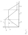
- FIG. 2 schematically shows an exemplary method sequence with reference to FIG Temperature diagram and a pressure diagram shown.
- a hydrostatic pressure is exerted.
- the temperature 40 is a temperature beyond the glass transition temperature of the matrix material.
- the hydrostatic pressure is in one Time interval 42 increased until a pressure level 44 is reached.
- the pressure is linearly ramped up (via the punch 12), such as shown in FIG.
- other pressure gradients are possible.
- time interval 46th the specimen is cooled, d. H. the temperature is lowered. Preferably becomes the pressure level 44 reached in this cooling interval 46 maintained.
- FIGS 3 (a) to 3 (c) are the microscopic operations in the component manufacturing shown schematically.
- Fig. 3 (a) the initial state of Component preform after consolidation and before the exercise of a hydrostatic pressure using a unit cell 48 shown.
- a fiber 50 is surrounded by matrix material 52.
- Two areas 54 and 56 are indicated in FIG Matrix material. (For illustrative reasons, the areas 54 and 56 at an exaggerated distance from the fiber 50.) These areas in the matrix material subject to a train in the circumferential direction (relative on the fiber 50) due to the different properties and in particular different thermal expansion coefficient between the Fiber 50 and the matrix material 52.
- a hydrostatic Applied pressure This is indicated in FIG. 3 (b).
- the hydrostatic pressure leads to a change in volume of the unit cell 48 (in Figure 3 (b) indicated through the cell 58).
- This volume change results in a boundary region 60 between the matrix material 52 and the fiber 50 to a mechanical Shape changing potential.
- the shape change potential in turn leads to a plasticization in the boundary region 60, d. H.
- the shape change energy is at least partially converted into dissipative energy, which is a Plastification causes. It then forms in the boundary region 60 a Plastactus Scheme 62 off.
- plastification in the boundary region 60 can be the Train in areas 54, 56 break down and it may even be generate a pressure in the circumferential direction relative to the fiber 50.
Landscapes
- Engineering & Computer Science (AREA)
- Mechanical Engineering (AREA)
- Chemical & Material Sciences (AREA)
- Composite Materials (AREA)
- Moulding By Coating Moulds (AREA)
- Casting Or Compression Moulding Of Plastics Or The Like (AREA)
- Manufacture Of Alloys Or Alloy Compounds (AREA)
Abstract
Description
- Figur 1
- eine Explosionsdarstellung eines Ausführungsbeispiels einer Vorrichtung zur Durchführung des erfindungsgemäßen Verfahrens;
- Figur 2
- schematisch ein Ausführungsbeispiel für einen Temperaturverlauf und Druckverlauf bei der Durchführung des erfindungsgemäßen Verfahrens und
- Figuren 3(a), 3(b) und 3(c)
- schematisch die mikroskopischen Verhältnisse bei der Durchführung des erfindungsgemäßen Verfahrens ausgehend von einem konsolidierten Bauteil-Vorkörper (Figur 3(a)) über Ausübung eines hydrostatischen Drucks (Figur 3(b)) bis zum Endzustand (Figur 3(c)).
Claims (31)
- Verfahren zur Herstellung eines Bauteils aus einem Faserverbundwerkstoff mit einer Matrix, in die Fasern eingelagert sind, bei dem bei fließfähigem oder kriechfähigem Matrixmaterial ein hydrostatischer Druck auf einen Bauteil-Vorkörper ausgeübt wird.
- Verfahren nach Anspruch 1, dadurch gekennzeichnet, daß das Matrixmaterial durch Erhitzen fließfähig oder kriechfähig gemacht wird.
- Verfahren nach Anspruch 1 oder 2, dadurch gekennzeichnet, daß bei Ausübung des hydrostatischen Drucks die Fließgrenze des Matrixmaterials erreicht oder überschritten ist oder ein Kriechniveau erreicht ist.
- Verfahren nach einem der vorangehenden Ansprüche, dadurch gekennzeichnet, daß der hydrostatische Druck so gewählt wird, daß die Eigenspannungen im Bauteil beeinflußt werden.
- Verfahren nach einem der vorangehenden Ansprüche, dadurch gekennzeichnet, daß der hydrostatische Druck so gewählt wird, daß die Eigenspannungen im Bauteil gezielt eingestellt werden.
- Verfahren nach einem der vorangehenden Ansprüche, dadurch gekennzeichnet, daß der hydrostatische Druck in Abhängigkeit des Verhältnisses der Kompressibilität des Matrixmaterials zur Kompressibilität der Fasern gewählt wird.
- Verfahren nach einem der vorangehenden Ansprüche, dadurch gekennzeichnet, daß der hydrostatische Druck oberhalb 500 bar liegt.
- Verfahren nach einem der vorangehenden Ansprüche, dadurch gekennzeichnet, daß der hydrostatische Druck extern auf den Bauteil-Vorkörper aufgebracht wird.
- Verfahren nach einem der vorangehenden Ansprüche, dadurch gekennzeichnet, daß ein hydrostatischer Druck nach Erhitzung des Matrixmaterials vor einer Abkühlphase ausgeübt wird.
- Verfahren nach einem der vorangehenden Ansprüche, dadurch gekennzeichnet, daß ein hydrostatischer Druck ausgeübt wird, bis der Bauteil-Vorkörper Umgebungstemperatur erreicht.
- Verfahren nach einem der vorangehenden Ansprüche, dadurch gekennzeichnet, daß hydrostatischer Druck ausgeübt wird, bis der Bauteil-Vorkörper ausgehärtet ist und/oder das Matrixmaterial nicht mehr fließfähig oder kriechfähig ist.
- Verfahren nach einem der vorangehenden Ansprüche, dadurch gekennzeichnet, daß das Matrixmaterial einen höheren thermischen Ausdehnungskoeffizienten hat als das Fasermaterial.
- Verfahren nach einem der vorangehenden Ansprüche, dadurch gekennzeichnet, daß die Fasern ein höheres E-Modul aufweisen als das Matrixmaterial.
- Verfahren nach einem der vorangehenden Ansprüche, dadurch gekennzeichnet, daß die Herstellung der Fließfähigkeit oder Kriechfähigkeit bei einem vorkonsolidierten Bauteil-Vorkörper erfolgt.
- Verfahren nach einem der Ansprüche 1 bis 13, dadurch gekennzeichnet, daß die Herstellung der Fließfähigkeit oder Kriechfähigkeit als Teil des Konsolidierungsprozesses des Bauteil-Vorkörpers erfolgt.
- Verfahren nach einem der vorangehenden Ansprüche, dadurch gekennzeichnet, daß das Faserverbundwerkstoff-Bauteil langfaserverstärkt ist oder durch Endlosfasern verstärkt.
- Verfahren nach einem der vorangehenden Ansprüche, dadurch gekennzeichnet, daß das Matrixmaterial ein thermoplastisches Material ist.
- Verfahren nach einem der Ansprüche 1 bis 16, dadurch gekennzeichnet, daß das Matrixmaterial ein Duromer ist.
- Verfahren nach einem der Ansprüche 1 bis 16, dadurch gekennzeichnet, daß das Matrixmaterial ein Metall ist.
- Verfahren nach einem der vorangehenden Ansprüche, dadurch gekennzeichnet, daß der Bauteil-Vorkörper isostatisch gepreßt wird.
- Verfahren nach Anspruch 20, dadurch gekennzeichnet, daß der Bauteil-Vorkörper beim isostatischen Pressen über eine Glasübergangstemperatur des Matrixmaterials geheizt ist.
- Verfahren nach Anspruch 20 oder 21, dadurch gekennzeichnet, daß eine Abkühlung bei im wesentlichen konstantem Druck erfolgt.
- Verfahren nach Anspruch 22, dadurch gekennzeichnet, daß nach der Abkühlung der Druck auf Atmosphärendruck zurückgenommen wird.
- Faserverbundwerkstoff-Bauteil, welches mit dem Verfahren gemäß einem der vorangehenden Ansprüche hergestellt ist.
- Vorrichtung zur Herstellung eines Faserverbundwerkstoff-Bauteils, umfassend eine Erwärmungseinrichtung (34), mit der ein Bauteil-Vorkörper (22) erhitzbar ist, um ein Matrixmaterial fließfähig oder kriechfähig zu machen, und eine Einrichtung (32) zum Ausüben eines hydrostatischen Drucks auf den Bauteil-Vorkörper (22).
- Vorrichtung nach Anspruch 25, dadurch gekennzeichnet, daß die Druckausübungseinrichtung (32) einen Preßstempel (12; 14) umfaßt.
- Vorrichtung nach Anspruch 25 oder 26, dadurch gekennzeichnet, daß eine Aufnahme (24) für den Bauteil-Vorkörper (22) vorgesehen ist, durch die der hydrostatische Druck auf den Bauteil-Vorkörper (22) übertragbar ist.
- Vorrichtung nach Anspruch 27, dadurch gekennzeichnet, daß der Bauteil-Vorkörper (22) durch die Aufnahme (24) umgeben ist.
- Vorrichtung nach Anspruch 27 oder 28, dadurch gekennzeichnet, daß die Aufnahme (24) aus Silikon hergestellt ist.
- Vorrichtung nach einem der Ansprüche 25 bis 29, dadurch gekennzeichnet, daß die Druckausübungseinrichtung (32) so ausgebildet ist, daß während einer Abkühlphase des Bauteil-Vorkörpers (22) ein hydrostatischer Druck aufbringbar ist.
- Vorrichtung nach einem der Ansprüche 25 bis 30, dadurch gekennzeichnet, daß durch die Druckausübungseinrichtung (32) hydrostatische Drücke größer als 500 bar aufbringbar sind.
Applications Claiming Priority (2)
| Application Number | Priority Date | Filing Date | Title |
|---|---|---|---|
| DE10330919 | 2003-07-03 | ||
| DE2003130919 DE10330919A1 (de) | 2003-07-03 | 2003-07-03 | Verfahren und Vorrichtung zur Herstellung eines Faserverbundwerkstoff-Bauteils |
Publications (2)
| Publication Number | Publication Date |
|---|---|
| EP1493549A2 true EP1493549A2 (de) | 2005-01-05 |
| EP1493549A3 EP1493549A3 (de) | 2011-05-25 |
Family
ID=33426887
Family Applications (1)
| Application Number | Title | Priority Date | Filing Date |
|---|---|---|---|
| EP04015030A Withdrawn EP1493549A3 (de) | 2003-07-03 | 2004-06-25 | Verfahren und Vorrichtung zur Herstellung eines Faserverbundwerkstoff-Bauteils |
Country Status (2)
| Country | Link |
|---|---|
| EP (1) | EP1493549A3 (de) |
| DE (1) | DE10330919A1 (de) |
Cited By (1)
| Publication number | Priority date | Publication date | Assignee | Title |
|---|---|---|---|---|
| CN114851599A (zh) * | 2022-05-06 | 2022-08-05 | 河海大学 | 纤维复合材料蠕变控制方法、纤维复合材料及加固方法 |
Family Cites Families (10)
| Publication number | Priority date | Publication date | Assignee | Title |
|---|---|---|---|---|
| US3201235A (en) * | 1962-07-02 | 1965-08-17 | Martin Marietta Corp | Hot press fabrication of thermoelectric elements |
| US4615933A (en) * | 1984-04-06 | 1986-10-07 | Rogers Corporation | Radome structure and method of manufacture thereof |
| JPS61273300A (ja) * | 1985-05-27 | 1986-12-03 | Tatsuro Kuratomi | 通電加熱と機械加圧を行う加熱加圧プレス装置 |
| DE3528629A1 (de) * | 1985-08-09 | 1987-02-12 | Man Technologie Gmbh | Verfahren zur herstellung eines rotorrohres |
| DE3813694A1 (de) * | 1988-04-22 | 1989-11-02 | Mobik Gmbh | Verfahren und anlage zur grossseriellen verarbeitung von hochleistungs-faserverbundwerkstoffen |
| JPH03284937A (ja) * | 1990-03-31 | 1991-12-16 | Three D Compo Res:Kk | 繊維強化複合材料の成形方法及び装置 |
| IT1258126B (it) * | 1992-12-23 | 1996-02-20 | Fiat Auto Spa | Procedimento a basso consumo energetico per la realizzazione di elementi in materiale composito. |
| US5830396A (en) * | 1993-01-21 | 1998-11-03 | Biomet, Inc. | Method for processing thermoplastics, thermosets and elastomers |
| CN1139901A (zh) * | 1994-10-28 | 1997-01-08 | 陶氏化学公司 | 改进的树脂压铸法 |
| US6214134B1 (en) * | 1995-07-24 | 2001-04-10 | The United States Of America As Represented By The Secretary Of The Air Force | Method to produce high temperature oxidation resistant metal matrix composites by fiber density grading |
-
2003
- 2003-07-03 DE DE2003130919 patent/DE10330919A1/de not_active Withdrawn
-
2004
- 2004-06-25 EP EP04015030A patent/EP1493549A3/de not_active Withdrawn
Cited By (2)
| Publication number | Priority date | Publication date | Assignee | Title |
|---|---|---|---|---|
| CN114851599A (zh) * | 2022-05-06 | 2022-08-05 | 河海大学 | 纤维复合材料蠕变控制方法、纤维复合材料及加固方法 |
| CN114851599B (zh) * | 2022-05-06 | 2023-03-14 | 河海大学 | 纤维复合材料蠕变控制方法、纤维复合材料及加固方法 |
Also Published As
| Publication number | Publication date |
|---|---|
| DE10330919A1 (de) | 2005-01-27 |
| EP1493549A3 (de) | 2011-05-25 |
Similar Documents
| Publication | Publication Date | Title |
|---|---|---|
| EP3523115B1 (de) | Verfahren und vorrichtung zum herstellen eines bauteils aus einem faserverbundwerkstoff | |
| AT395693B (de) | Einrichtung zum spritzpressen | |
| EP4017694B1 (de) | Verfahren und vorrichtung zum herstellen eines bauteils aus einem faserverbundwerkstoff | |
| DE102011077468A1 (de) | RTM-Verfahren und dichtungsloses Werkzeug zur Herstellung von faserverstärkten Kunststoffformteilen | |
| WO2021023829A1 (de) | Verfahren zum reparieren eines faserverbundbauteils | |
| EP4017712B1 (de) | Verfahren zum herstellen eines bauteils aus einem faserverbundwerkstoff | |
| EP1626859B1 (de) | Verfahren zur herstellung eines faserverbundwerkstoff-bauteils sowie zwischenprodukt f r ein solches verfahren | |
| EP4017710B1 (de) | Verfahren zur herstellung von formteilen aus faserverbund-werkstoff | |
| DE69607445T2 (de) | Verfahren zur Herstellung eines Gegenstandes aus Verbundwerkstoff durch Transfer-Spritzgiessen von Kunstharz (R.T.M.) und dadurch hergestellter Gegenstand | |
| DE102012102594A1 (de) | Hydraulische Taktpresse | |
| DE10258630A1 (de) | Verfahren zu Herstellung langfaserverstärkter, thermoplastischer Bauteile | |
| EP0413714A1 (de) | Verfahren und anlage zur grossseriellen verarbeitung von hochleistungs-faserverbundwerkstoffen | |
| DE102020127719B3 (de) | Pressvorrichtung und Verfahren zur Herstellung eines Presserzeugnisses | |
| DE10330919A1 (de) | Verfahren und Vorrichtung zur Herstellung eines Faserverbundwerkstoff-Bauteils | |
| DE102017006050B4 (de) | Verfahren zur Herstellung eines FKV-Bauteils mit lokaler Verdichtung und Verfahren zur Herstellung eines Bauteilverbunds | |
| DE102019114710A1 (de) | Vorrichtung und Verfahren | |
| EP3630479B1 (de) | Presse und verfahren zum herstellen des formteils | |
| EP2999583B1 (de) | Verfahren zum herstellen eines werkzeugs für die herstellung eines faserverbundbauteils | |
| DE102015119401A1 (de) | Verfahren zur Herstellung eines Sandwichbauteils | |
| WO2020207672A1 (de) | Verfahren zur herstellung einer verbindung zwischen zwei bauteilen | |
| DE102013012226B4 (de) | Verfahren zur Herstellung eines faserverstärkten Kunststoffbauteils durch Spritzpressen | |
| WO2021032665A1 (de) | Verfahren und vorrichtung zum herstellen eines bauteils aus einem faserbundwerkstoff | |
| WO2001007223A1 (de) | Verfahren zum pressen zylindrischer verbundkörper | |
| DE102023126685A1 (de) | Verfahren zur Herstellung eines gekrümmten Faserverbundbauteils | |
| EP3317073A1 (de) | VERFAHREN ZUR BEEINFLUSSUNG DER ORIENTIERUNG VON FÜLLSTOFFEN IN EINER KUNSTSTOFFSCHMELZE WÄHREND EINER HERSTELLUNG EINES FORMKÖRPERS IN EINEM SPRITZGIEßVERFAHREN |
Legal Events
| Date | Code | Title | Description |
|---|---|---|---|
| PUAI | Public reference made under article 153(3) epc to a published international application that has entered the european phase |
Free format text: ORIGINAL CODE: 0009012 |
|
| AK | Designated contracting states |
Kind code of ref document: A2 Designated state(s): AT BE BG CH CY CZ DE DK EE ES FI FR GB GR HU IE IT LI LU MC NL PL PT RO SE SI SK TR |
|
| AX | Request for extension of the european patent |
Extension state: AL HR LT LV MK |
|
| RAP1 | Party data changed (applicant data changed or rights of an application transferred) |
Owner name: DEUTSCHES ZENTRUM FUER LUFT- UND RAUMFAHRT E.V. |
|
| PUAL | Search report despatched |
Free format text: ORIGINAL CODE: 0009013 |
|
| AK | Designated contracting states |
Kind code of ref document: A3 Designated state(s): AT BE BG CH CY CZ DE DK EE ES FI FR GB GR HU IE IT LI LU MC NL PL PT RO SE SI SK TR |
|
| AX | Request for extension of the european patent |
Extension state: AL HR LT LV MK |
|
| RIC1 | Information provided on ipc code assigned before grant |
Ipc: B30B 11/00 20060101ALI20110419BHEP Ipc: B29C 70/34 20060101ALI20110419BHEP Ipc: B29C 70/46 20060101ALI20110419BHEP Ipc: B29C 70/44 20060101AFI20041015BHEP |
|
| AKY | No designation fees paid | ||
| REG | Reference to a national code |
Ref country code: DE Ref legal event code: R108 |
|
| REG | Reference to a national code |
Ref country code: DE Ref legal event code: R108 Effective date: 20120201 |
|
| STAA | Information on the status of an ep patent application or granted ep patent |
Free format text: STATUS: THE APPLICATION IS DEEMED TO BE WITHDRAWN |
|
| 18D | Application deemed to be withdrawn |
Effective date: 20111126 |