EP1493496A1 - Coating apparatus and method - Google Patents
Coating apparatus and method Download PDFInfo
- Publication number
- EP1493496A1 EP1493496A1 EP04291649A EP04291649A EP1493496A1 EP 1493496 A1 EP1493496 A1 EP 1493496A1 EP 04291649 A EP04291649 A EP 04291649A EP 04291649 A EP04291649 A EP 04291649A EP 1493496 A1 EP1493496 A1 EP 1493496A1
- Authority
- EP
- European Patent Office
- Prior art keywords
- substrate
- coating
- fluid
- roll
- opening
- Prior art date
- Legal status (The legal status is an assumption and is not a legal conclusion. Google has not performed a legal analysis and makes no representation as to the accuracy of the status listed.)
- Granted
Links
Images


Classifications
-
- B—PERFORMING OPERATIONS; TRANSPORTING
- B05—SPRAYING OR ATOMISING IN GENERAL; APPLYING FLUENT MATERIALS TO SURFACES, IN GENERAL
- B05C—APPARATUS FOR APPLYING FLUENT MATERIALS TO SURFACES, IN GENERAL
- B05C5/00—Apparatus in which liquid or other fluent material is projected, poured or allowed to flow on to the surface of the work
- B05C5/02—Apparatus in which liquid or other fluent material is projected, poured or allowed to flow on to the surface of the work the liquid or other fluent material being discharged through an outlet orifice by pressure, e.g. from an outlet device in contact or almost in contact, with the work
- B05C5/0254—Coating heads with slot-shaped outlet
- B05C5/0266—Coating heads with slot-shaped outlet adjustable in length, e.g. for coating webs of different width
-
- B—PERFORMING OPERATIONS; TRANSPORTING
- B05—SPRAYING OR ATOMISING IN GENERAL; APPLYING FLUENT MATERIALS TO SURFACES, IN GENERAL
- B05C—APPARATUS FOR APPLYING FLUENT MATERIALS TO SURFACES, IN GENERAL
- B05C3/00—Apparatus in which the work is brought into contact with a bulk quantity of liquid or other fluent material
- B05C3/18—Apparatus in which the work is brought into contact with a bulk quantity of liquid or other fluent material only one side of the work coming into contact with the liquid or other fluent material
-
- B—PERFORMING OPERATIONS; TRANSPORTING
- B05—SPRAYING OR ATOMISING IN GENERAL; APPLYING FLUENT MATERIALS TO SURFACES, IN GENERAL
- B05C—APPARATUS FOR APPLYING FLUENT MATERIALS TO SURFACES, IN GENERAL
- B05C5/00—Apparatus in which liquid or other fluent material is projected, poured or allowed to flow on to the surface of the work
- B05C5/02—Apparatus in which liquid or other fluent material is projected, poured or allowed to flow on to the surface of the work the liquid or other fluent material being discharged through an outlet orifice by pressure, e.g. from an outlet device in contact or almost in contact, with the work
- B05C5/0254—Coating heads with slot-shaped outlet
- B05C5/0262—Coating heads with slot-shaped outlet adjustable in width, i.e. having lips movable relative to each other in order to modify the slot width, e.g. to close it
Abstract
Description
L'invention a pour objet un nouveau dispositif et un nouveau procédé d'enduction de fluide, notamment de fluide à seuil d'écoulement.The subject of the invention is a new device and a new process for coating fluid, in particular fluid at the threshold of flow.
On appelle « enduction » l'application d'une substance fluide ou fluidifiée sur un support ou substrat et, par extension, la couche de la substance déposée comme enduit elle-même. Des adhésifs tels que les réactifs polyuréthannes bi-composants (PU2K) solvantés sont fréquemment utilisés pour l'enduction de substrats tels que des bandes tissées ou tricotées. L'enduction conduit à un renforcement mécanique du substrat et connaít diverses applications, telles que la fixation du tissage, le rasage des bouclettes du substrat ou la découpe du substrat.The term "coating" is applied to the application of a substance fluid or fluidized on a support or substrate and extension, the layer of the substance deposited as a coating herself. Adhesives such as reagents two-component polyurethanes (PU2K) are frequently used for coating substrates such as woven or knitted strips. Coating leads to a mechanical reinforcement of the substrate and know various applications, such as fixing weaving, shaving loops of the substrate or the cutting of the substrate.
On connaít des encolleuses standards à rouleau(x) avec une alimentation par débordement et recyclage, telles qu'utilisées pour les adhésifs PU2K solvantés. On connaít en outre des dispositifs d'enduction utilisant une buse à lèvre, tel qu'il est pratiqué pour des HMPUR (de l'anglais « Reactive Hot-Melt Polyurethanes »). Or, ces dispositifs donnent lieu à des arrêts de production fréquents dus, par exemple, à des bouchages et à la nécessité de purger et rincer les dispositifs.We know standard glue rollers (x) with overflow and recycling, such as used for solvent-based PU2K adhesives. We know in addition to coating devices using a nozzle to lip, as practiced for HMPUR "Reactive Hot-Melt Polyurethanes"). Now, these devices give rise to frequent production stoppages due to for example, blockages and the need to purge and rinse the devices.
Il existe donc un besoin pour un dispositif d'enduction qui permette de résoudre les problèmes évoqués ci-dessus.There is therefore a need for a device coating that solves the problems mentioned above.
L'invention a pour objet un dispositif d'enduction comprenant un bac d'enduction avec une ouverture et un rouleau d'enduction, dans lequel le rouleau est en regard de l'ouverture.The subject of the invention is a coating device comprising a coating pan with an opening and a coating roll, in which the roll is facing of the opening.
Dans des modes de réalisation préférés, l'invention comprend une ou plusieurs des caractéristiques suivantes :
- un espace est ménagé entre le bac et le rouleau d'enduction, de préférence compris entre 0,1 et 7 mm ;
- au moins un tiroir coulisse dans le dispositif ;
- le dispositif comprend des moyens de rappel du bac d'enduction vers une position de fonctionnement ;
- le dispositif comprend au moins un rouleau de guidage du substrat avec, éventuellement, des galets de guidage ;
- le dispositif comprend des moyens de positionnement du rouleau de guidage selon un axe, éventuellement excentré par rapport à l'axe de rotation du rouleau de guidage ;
- le dispositif comprend en outre un four ;
- le dispositif comprend en outre un rouleau de bobinage du substrat.
- a space is provided between the tray and the coating roll, preferably between 0.1 and 7 mm;
- at least one drawer slides in the device;
- the device comprises return means of the coating tray to an operating position;
- the device comprises at least one guide roller of the substrate with, optionally, guide rollers;
- the device comprises means for positioning the guide roller along an axis, possibly eccentric with respect to the axis of rotation of the guide roller;
- the device further comprises an oven;
- the device further comprises a substrate winding roller.
L'invention concerne également un procédé d'enduction d'un substrat par un fluide comprenant les étapes de : (i) fourniture d'un substrat et d'un fluide, (ii) application du fluide sur le substrat et (iii) cisaillement du fluide par le substrat mis en mouvement relatif par rapport au fluide.The invention also relates to a coating process a substrate by a fluid comprising the steps of: (i) providing a substrate and a fluid, (ii) applying fluid on the substrate and (iii) fluid shear by the substrate set in motion relative to the fluid.
Dans des modes de réalisation préférés, l'invention comprend également une ou plusieurs des caractéristiques suivantes :
- le procédé comprend en outre une étape (iv) d'extension du substrat au moins partiellement concomitante avec l'étape de cisaillement du fluide ;
- le substrat fourni à l'étape (i) est un substrat maillé et l'étape (iv) est une étape d'extension des mailles du substrat ;
- les caractéristiques du fluide fourni comprennent au moment de l'étape (ii) : une viscosité Brookfield à 23°C comprise entre 100 et 200000 mPas, de préférence entre 200 et 4000 mPas, un seuil d'écoulement compris entre 1 et 5000 Pa, de préférence entre 10 et 500 Pa et un délai d'obtention de seuil d'écoulement ajusté entre 1 et 20 secondes, de préférence entre 2 et 10 secondes ;
- le fluide fourni est un adhésif réactif Polyuréthanne bi-composant, qui comprend une partie résine comprenant au moins un polyol et une polyamine, et une partie durcisseur comprenant au moins un isocyanate ;
- le procédé comprend en outre une étape (v) de chauffage du substrat ;
- le procédé comprend en outre une étape (vi) d'enroulement du substrat ;
- le procédé utilise un dispositif d'enduction selon l'invention.
- the method further comprises a step (iv) of extending the substrate at least partially concomitant with the fluid shearing step;
- the substrate provided in step (i) is a mesh substrate and step (iv) is a step of extending the mesh of the substrate;
- the characteristics of the fluid supplied comprise, at the time of step (ii): a Brookfield viscosity at 23 ° C. of between 100 and 200000 mPas, preferably between 200 and 4000 mPas, a yield point of between 1 and 5000 Pa, preferably between 10 and 500 Pa and a time to obtain adjusted flow threshold between 1 and 20 seconds, preferably between 2 and 10 seconds;
- the fluid supplied is a two-component polyurethane reactive adhesive, which comprises a resin part comprising at least one polyol and a polyamine, and a hardener part comprising at least one isocyanate;
- the method further comprises a step (v) of heating the substrate;
- the method further comprises a step (vi) of winding the substrate;
- the method uses a coating device according to the invention.
L'invention concerne également un substrat enduit susceptible d'être obtenu par le procédé d'enduction d'un substrat selon l'invention. Dans un mode de réalisation préféré, le substrat est un textile auto-agrippant.The invention also relates to a coated substrate obtainable by the coating process of a substrate according to the invention. In one embodiment preferred, the substrate is a self-gripping textile.
D'autres caractéristiques et avantages de l'invention apparaítront à la lecture de la description qui suit de modes de réalisation préférés de l'invention, donnée à titre d'exemple et en référence aux dessins annexés montrant :
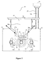
- Figure 1 : une vue en perspective d'un dispositif d'enduction selon l'invention ;
- Figure 2 : une vue de côté d'un dispositif d'enduction selon l'invention ;
- Figure 3 : une vue de dessus d'une partie d'un dispositif d'enduction selon l'invention ; et
- Figure 4 : une illustration schématique d'un substrat inséré dans un dispositif d'enduction selon l'invention, vu de profil.
- Figure 1 is a perspective view of a coating device according to the invention;
- Figure 2 is a side view of a coating device according to the invention;
- Figure 3: a top view of a portion of a coating device according to the invention; and
- Figure 4: a schematic illustration of a substrate inserted into a coating device according to the invention, seen in profile.
L'invention propose un dispositif d'enduction comprenant un bac d'enduction, avec une ouverture, et un rouleau d'enduction, dans lequel le rouleau est en regard de l'ouverture.The invention proposes a coating device comprising a coating pan, with an opening, and a coating roll, in which the roll is facing of the opening.
Le bac d'enduction est apte à recevoir une substance devant être enduite sur un substrat. L'ouverture est de dimension inférieure ou égale à la surface de rouleau en regard du bac. Un fluide, par exemple un adhésif à seuil d'écoulement, peut être introduit dans le bac d'enduction. Un substrat, par exemple une bande de textile, peut être inséré entre le rouleau et l'ouverture, l'endos du substrat (c'est-à-dire le côté à enduire) faisant face à l'ouverture.The coating pan is adapted to receive a substance to be coated on a substrate. The opening is dimension less than or equal to the roll surface in look at the bin. A fluid, for example a threshold adhesive flow, can be introduced into the coating tank. A substrate, for example a textile strip, can be inserted between the roll and the opening, the back of the substrate (that is, the side to be coated) facing the opening.
Sous l'action de la gravité ou d'un quelconque moyen de pression du fluide approprié, le fluide vient s'appliquer sur le substrat. Lorsqu'il est mis en mouvement relativement par rapport au fluide, le substrat exerce une contrainte de cisaillement sur une couche du fluide, par exemple une couche horizontale inférieure lorsque le fluide est appliqué sur le substrat sous l'action de la gravité. Lorsque le fluide à seuil d'écoulement est soumis à une contrainte de cisaillement suffisante par la bande de substrat, il peut s'écouler et alors enduire le substrat.Under the influence of gravity or any means pressure of the appropriate fluid, the fluid comes apply on the substrate. When put in motion relative to the fluid, the substrate exerts a shear stress on a layer of the fluid, by example a lower horizontal layer when the fluid is applied to the substrate under the action of gravity. When the flow threshold fluid is subjected to a sufficient shear stress by the tape substrate, it can flow and then coat the substrate.
Un tel dispositif permet l'enduction de la bande avec une bonne pénétration du fluide dans le substrat. Le substrat peut simultanément être soumis à une extension au niveau du rouleau d'enduction, ce qui améliore la pénétration du fluide. L'utilisation de ce dispositif avec un fluide présentant à la fois un seuil d'écoulement et une montée en cohésion rapide permet en outre une bonne pénétration dans le substrat, par exemple dans la trame d'un textile, sans pour autant le traverser. Il est en outre possible d'adapter conjointement la vitesse d'entraínement de la bande et les propriétés physico-chimique du fluide afin d'obtenir un contrôle précis du grammage d'adhésif déposé et, ainsi, des propriétés du substrat adaptées à diverses applications (fixation du tissage, rasage des bouclettes du substrat, découpe longitudinale, découpe transversale au massicot, aboutage par soudure aux ultrasons et fixation ou raidissement des lisières). De plus, l'utilisation d'un rouleau d'enduction donne de meilleurs résultats d'enduction qu'un dispositif classique utilisant une buse à lèvres. En particulier, on obtient grâce à l'invention une enduction plus tendue et plus brillante.Such a device allows the coating of the strip with good penetration of the fluid into the substrate. The substrate can be simultaneously extended to level of the coating roll, which improves the fluid penetration. Using this device with a fluid having both a flow threshold and a rapid cohesion build also allows good penetration into the substrate, for example in the weft of a textile, without crossing it. He is in additionally possible to jointly adjust the speed drive band and physicochemical properties fluid to obtain precise control of weight of adhesive deposited and thus the properties of the suitable for various applications (fixing the weaving, shaving substrate loops, cutting longitudinal, cutting transverse to the cutter, butting by ultrasonic welding and fixation or stiffening of edges). In addition, the use of a coating roll gives better coating results than a device classic using a lip nozzle. In particular, obtained thanks to the invention a more tense coating and more brilliant.
La figure 1 montre une vue en perspective d'un exemple
de dispositif d'enduction selon l'invention, utilisant la
gravité comme moyen d'application du fluide sur le
substrat. Le dispositif 10 comprend un bac d'enduction 21
délimité, dans sa partie supérieure, par quatre flancs
26a,26b,26c,26d. Ces flancs peuvent avantageusement être
faits de polytétrafluoroéthylène, compte tenu de la
résistance aux substances chimiques, la stabilité thermique
et le faible coefficient de friction de celui-ci. Dans sa
partie inférieure, le bac 21 comprend une ouverture 22
formée par les rebords 27,28 de deux autres flancs 27a,28a,
lesquels seront décrits en référence aux figures 2 et 3.
Sous son ouverture 22 inférieure, le dispositif d'enduction
10 comprend en outre un rouleau d'enduction 31 en regard de
l'ouverture 22, sous celle-ci, et dont la largeur est
généralement comprise entre 20 et 60 cm. La largeur du
rouleau n'est cependant pas limitée sur le plan théorique ;
elle l'est en pratique compte tenu des risques de
déformation mécaniques du rouleau (flambage). Le diamètre
du rouleau est de préférence inférieur à 100 mm et de plus
grande préférence compris entre 30 et 50 mm.Figure 1 shows a perspective view of an example
coating device according to the invention, using the
gravity as a means of applying the fluid to the
substrate. The
Grâce à ce dispositif 10, un adhésif peut être
introduit dans le bac d'enduction 21 et une bande de
substrat 40 peut être insérée entre le rouleau 31 et
l'ouverture inférieure 22, à travers un espace ménagé à cet
effet et, au besoin, adapté à l'épaisseur de la bande
(relief inclus). L'espace ménagé entre le rouleau 31 et
l'ouverture inférieure 22 est typiquement compris entre 0,1
et 7 mm, selon le grammage d'enduction souhaité. Par
exemple, ménager un espace d'environ 5 mm, correspondant à
une épaisseur d'un substrat avec son relief, permet
d'obtenir un grammage compris entre 50 et 5000 g/m2, selon
la résistance à l'écrasement du relief. La face à enduire
du substrat 40 est placée du côté de l'ouverture 22. Sous
l'action de la gravité, l'adhésif vient s'appliquer sur
tout ou partie de la bande, l'ouverture ayant des
dimensions inférieures ou égales à celles du rouleau.With this
Un tel dispositif est particulièrement bien adapté à la mise en oeuvre d'un procédé d'enduction d'un substrat par un fluide, selon l'invention. Un tel fluide peut, par exemple, être un fluide à seuil d'écoulement, de préférence sans solvant. Le procédé selon l'invention comprend les étapes : de fourniture d'un substrat et d'un fluide ; d'application du fluide sur le substrat ; et de cisaillement du fluide par le substrat mis en mouvement relatif par rapport au fluide.Such a device is particularly well adapted to the implementation of a process for coating a substrate with a fluid according to the invention. Such a fluid can, for for example, be a flow threshold fluid, preferably without solvent. The method according to the invention comprises steps of providing a substrate and a fluid; applying the fluid to the substrate; and of shearing of the fluid by the moving substrate relative to the fluid.
Le procédé selon l'invention propose donc d'appliquer le fluide sur un substrat et d'exercer une contrainte de cisaillement sur ce fluide. Lorsque la contrainte de cisaillement est suffisante pour surmonter le seuil d'écoulement de ce fluide, celui-ci peut s'écouler et mouiller correctement le substrat. Lorsque la contrainte de cisaillement redevient inférieure au seuil d'écoulement (par exemple lorsque la contrainte cesse), le fluide ne s'écoule plus.The method according to the invention therefore proposes to apply the fluid on a substrate and exert a stress of shear on this fluid. When the constraint of shear is enough to overcome the threshold flow of this fluid, it can flow and properly wet the substrate. When the constraint of shear becomes below the flow threshold (for example, when the stress ceases), the fluid does not no longer flows.
Il est donc possible de réaliser une enduction d'un substrat, qui mouille correctement ce substrat sans pour autant le traverser et ce, en ajustant la contrainte de cisaillement, son moment et celui de l'application du fluide.It is therefore possible to make a coating of a substrate, which properly wets this substrate without to cross it and this, by adjusting the stress of shear, its timing and that of the application of fluid.
Le procédé d'enduction selon l'invention peut en outre comprendre une étape d'extension du substrat 40 (c'est-à-dire une ouverture du relief ou des mailles 42 du substrat, le cas échéant) au moins partiellement concomitante avec l'étape de cisaillement du fluide, afin d'améliorer le cisaillement du fluide par le substrat ainsi que la pénétration du fluide dans le substrat.The coating process according to the invention may furthermore include a step of extending the substrate 40 (i.e. an opening of the relief or meshes 42 of the substrate, where appropriate) at least partially concomitant with the shearing stage of the fluid, in order to improve the shearing of the fluid by the substrate as well as the penetration of the fluid into the substrate.
Le dispositif et le procédé selon l'invention sont bien adaptés pour une utilisation avec un fluide à seuil d'écoulement tel qu'un fluide dont la viscosité, mesurée à l'aide d'un viscosimètre standard Brookfield à 23°C, est comprise entre 100 et 200000 mPas, de préférence entre 200 et 4000 mPas, avec un seuil d'écoulement compris entre 1 et 5000 Pa, de préférence entre 10 et 500 Pa et un délai d'obtention du seuil d'écoulement ajusté entre 1 et 20 secondes et, de préférence, entre 2 et 10 secondes. Un tel profil de fluide permet un pompage facile.The device and the method according to the invention are well suited for use with a threshold fluid flow such as a fluid whose viscosity, measured at using a Brookfield standard viscometer at 23 ° C, is between 100 and 200000 mPas, preferably between 200 and 4000 mPas, with a flow threshold of between 1 and 5000 Pa, preferably between 10 and 500 Pa and a delay to obtain the adjusted flow threshold between 1 and 20 seconds, and preferably between 2 and 10 seconds. Such fluid profile allows easy pumping.
Le fluide peut à la fois présenter un seuil d'écoulement et un comportement newtonien une fois le seuil franchi, et rester parfaitement adapté pour une utilisation avec le dispositif selon l'invention. En fait, même s'il est plus particulièrement adapté aux fluides à seuil d'écoulement, le dispositif selon l'invention est aussi compatible avec une large gamme de fluides sans seuil d'écoulement, c'est-à-dire ayant un seuil inférieur à 1 Pa, mais présentant une viscosité appropriée, comprise entre 100 et 200000 mPas.The fluid can both have a threshold of flow and Newtonian behavior once the threshold crossed, and stay perfectly suited for use with the device according to the invention. In fact, even if he is more particularly adapted to threshold fluids flow, the device according to the invention is also compatible with a wide range of fluids without threshold flow, that is to say having a threshold of less than 1 Pa, but having an appropriate viscosity between 100 and 200000 mPas.
En particulier, le dispositif et le procédé sont particulièrement bien adaptés pour l'application d'un adhésif réactif Polyuréthanne bi-composant (PU2K), comprenant une partie résine comprenant au moins un polyol et une polyamine, et une partie durcisseur comprenant au moins un isocyanate. Un tel mélange réactif est susceptible de présenter un seuil d'écoulement. Il peut en outre avantageusement être utilisé sans solvant, c'est-à-dire ayant une teneur en solvant de moins de 1% et, de préférence, de moins de 500 ppm en poids, dans le dispositif selon l'invention.In particular, the device and the method are particularly well suited for the application of a two-component polyurethane (PU2K) reactive adhesive, comprising a resin part comprising at least one polyol and a polyamine, and a hardener portion comprising at least minus one isocyanate. Such a reactive mixture is susceptible to present a threshold of flow. It can furthermore advantageously be used without solvent, that is to say having a solvent content of less than 1% and, preferably less than 500 ppm by weight, in the device according to the invention.
L'entraínement de la bande de substrat 40 autour du
rouleau 31 conduit à un cisaillement du fluide par le
substrat. Un cisaillement suffisant d'un adhésif présentant
un profil tel que décrit ci-avant augmente la fluidité de
cet adhésif au niveau de l'ouverture inférieure, entraínant
alors un mouillage correct des fibres du substrat.The drive of the
Le passage de la bande sur le rouleau 31 peut en outre
conduire à une extension du substrat 40 (c'est-à-dire à une
ouverture du relief ou des mailles 42 du substrat, le cas
échéant), côté face d'enduction. L'importance de cette
extension varie notamment en fonction du diamètre du
rouleau 31 ainsi que des angles formés par le substrat de
part et d'autre du rouleau 31 : on parlera d'angles
d'arrivée et d'échappement selon que l'on se situe en aval
ou en amont du rouleau 31, respectivement. Cette extension
est au moins partiellement concomitante avec le
cisaillement de l'adhésif, ce qui améliore le mouillage des
fibres du substrat par l'adhésif.The passage of the strip on the
A cet égard, il convient de noter que, selon un mode
de réalisation, le diamètre de rouleau 31 d'enduction
recherché est le plus petit possible, afin de permettre une
extension maximale du substrat 40, pour autant que ce
diamètre n'induise pas de flambage notable du rouleau. Un
diamètre de rouleau compris entre 30 et 50 mm permet
d'optimiser l'extension du substrat 40. En pratique, un
diamètre de 40 mm s'avère particulièrement bien adapté à
l'extension de substrats de types variés. L'extension du
substrat 40 se résorbe juste après le passage sur le
rouleau d'enduction 31 tandis que l'adhésif reprend de la
cohésion après le cisaillement. L'utilisation d'un tel
dispositif 10 avec un adhésif présentant à la fois un seuil
d'écoulement et une montée en cohésion rapide améliore la
pénétration du fluide dans le substrat sans pour autant le
traverser. La vitesse d'entraínement de la bande peut en
outre être ajustée (1 à 200 m/min, de préférence 10 à 50
m/min) conjointement avec les propriétés physico-chimiques
de l'adhésif pour permettre un contrôle précis du grammage
d'adhésif déposé, par exemple compris entre 10 et 500 g/m2,
selon le relief du support. Un tel ajustement permet en
outre d'obtenir des propriétés variées, selon l'application
envisagée, comme la fixation du tissage, le rasage des
bouclettes du substrat, la découpe longitudinale ou
transversale au massicot, l'aboutage par soudure aux
ultrasons et la fixation ou le raidissement des lisières.
Le dispositif d'enduction selon l'invention est en outre
particulièrement bien adapté à l'enduction de textiles
auto-agrippants. De plus, l'utilisation d'un rouleau
d'enduction 31 donne de meilleurs résultats d'enduction
qu'un dispositif classique utilisant une buse à lèvres. En
particulier, on obtient grâce à l'invention une enduction
plus tendue et plus brillante. Par ailleurs, le dispositif
10 selon l'invention ne donne pas lieu à des arrêts de
production fréquents, même lorsqu'il est utilisé avec des
adhésifs ayant une montée en cohésion rapide.In this respect, it should be noted that
embodiment, the diameter of
D'autres éléments 32,32a,32b,34 de la figure 1 seront
décrits en référence à la figure 2.
La figure 2 montre une vue de côté d'un dispositif
d'enduction 10 selon l'invention. Cette vue montre les
rebords 27,28 des flancs 27a,28a, définissant l'ouverture
22 inférieure du bac 21, sous laquelle est situé le rouleau
31. Les flancs 27a,28a peuvent être inclinés, de sorte que
le bac 21 présente une section en entonnoir, avec un angle
de trémie adapté pour faciliter l'écoulement du fluide.
Cependant, un autre type de section, par exemple
rectangulaire, pourrait également convenir.Figure 2 shows a side view of a device
of
Il peut également être avantageux de prévoir un
dispositif d'enduction 10 comprenant en outre un ou deux
flancs 27a,28a mobiles. En particulier, les flancs 27a,28a
peuvent coulisser selon les flèches montrées sur la figure
2. Il est ainsi possible d'ajuster l'espace ménagé entre le
bac et le rouleau d'enduction, en fonction de l'épaisseur
de substrat et/ou conjointement avec des propriétés
physico-chimiques de l'adhésif, en vue de l'obtention de
propriétés spécifiques de la bande de substrat 40 (voir ci-avant).It may also be advantageous to provide
Il peut en outre être avantageux de prévoir un
dispositif d'enduction 10 dans lequel la section des
rebords 27,28 est en forme de pointe arrondie à son
extrémité (le cercle osculateur à l'extrémité d'un rebord a
un diamètre typiquement compris entre 0,5 et 15 mm), afin
de favoriser le glissement de la bande et d'éviter tout
accroc avec celle-ci lorsqu'elle est entraínée sur le
rouleau 31. Le profil des rebords 27,28 de l'exemple de
dispositif représenté sur la figure 2 résulte d'un
compromis entre leur usinabilité (les rebords sont dans cet
exemple faits d'un matériau métallique) et l'angle
d'échappement α recherché. L'angle correspondant à la
pointe, en section, est typiquement compris entre 20° et
40°. Il peut cependant être adapté de sorte à ménager un
angle d'échappement α supérieur à l'angle de mouillage du
fluide afin d'éviter l'accumulation de fluide contre un
rebord. Ceci permet d'allonger la durée de fonctionnement
en continu du dispositif avant interruption pour nettoyage
et, donc, de diminuer la fréquence d'arrêt de production.In addition, it may be advantageous to provide
Il est en outre avantageux de pouvoir faire coulisser
au moins un tiroir 23,24 dans le dispositif 10. Par
exemple, il est possible de prévoir un passage 25 aménagé
dans au moins un flanc 26 afin de pouvoir faire coulisser
un ou des tiroir(s) 23,24 le long de la rigole formée par
les rebords 27,28 et ce, depuis l'extérieur du dispositif
10 grâce à des moyens de préhension de tiroirs 23a,24a.
Cette possibilité sera décrite en référence à la figure 3.It is also advantageous to be able to slide
at least one
En outre, on peut prévoir des moyens de rappel 29 du
bac d'enduction 21 contre le rouleau d'enduction 31 via les
rebords 27,28 ou contre la bande, lorsque celle-ci est
insérée. Toutefois, lorsqu'il est souhaitable de ménager un
espace entre le bac 21 et le rouleau d'enduction 31, ces
moyens 29 sont adaptés de sorte à rappeler le bac 21 vers
une position de fonctionnement. Cette position de
fonctionnement laisse un espace libre entre le bac 21 et le
rouleau d'enduction 31. Dans l'exemple montré sur la
figure, les moyens de rappel 29 comprennent un ou plusieurs
ressorts à spires. Le cas échéant, les ressorts peuvent
être en contact avec les surfaces du support 12, d'un plat
14 et d'un manchon 16. Ce manchon peut éventuellement être
ajustable, c'est-à-dire qu'il peut être vissé sur une tige
16a pour régler la force de rappel du ressort. Le montage
précédent permet également d'ajuster la position de
fonctionnement du bac 21 (notamment la hauteur du bac, les
angles de tangage et roulis), d'amortir les vibrations du
système (par exemple lors du passage de joints bout à bout
de la bande de substrat) et de libérer des contraintes
occasionnelles engendrées par le mouvement de la bande de
substrat 40.In addition, recall means 29 can be provided.
Il peut en outre être avantageux de prévoir un ou
plusieurs rouleaux 32 de guidage de la bande de substrat
40, comme dans l'exemple de dispositif 10 montré sur la
figure 2. Le substrat peut être inséré au dessous ou au
dessus d'un rouleau de guidage, selon l'angle d'arrivée
et/ou d'échappement recherché. Ces angles sont ceux formés
entre la surface supérieure du substrat et la surface
inférieure d'un rebord 27, 28. Les angles de mouillage des
fluides utilisés varient typiquement entre 15 et 40°. La
figure montre également des moyens de positionnement
32a,32b de rouleau de guidage. Dans cet exemple, ces moyens
comprennent un écrou 32a vissé sur l'arbre d'un rouleau 32
de guidage et serrant une rondelle en appui sur un haricot
32b. L'écrou 32a permet ainsi d'ajuster la position de
l'arbre du rouleau 32 de guidage situé d'un côté du rouleau
d'enduction 31. Des moyens de positionnement similaires
peuvent être prévus sur le côté opposé du rouleau
d'enduction 31 afin de permettre un réglage de la position
d'un autre rouleau 32 de guidage. Un rouleau 32 peut par
exemple être pourvu de galets 34, dont l'écartement est
éventuellement ajustable à la laize de substrat, afin de
guider la bande de substrat 40 à travers le dispositif
d'enduction 10.In addition, it may be advantageous to provide one or
Il est en outre possible de prévoir un rouleau de guidage de forme bombée, c'est-à-dire dont la surface extérieure a une courbure régulière et légèrement convexe dans un plan contenant l'axe du rouleau, pour permettre le guidage et le centrage du substrat.It is also possible to provide a roll of curved guide, that is to say the surface of which outer has a regular curvature and slightly convex in a plane containing the axis of the roll, to allow the guiding and centering the substrate.
Il est en outre possible de prévoir des moyens de
positionnement 32a,32b selon un axe excentré par rapport à
l'arbre du rouleau 32, à l'instar de l'exemple montré sur
la figure 2. Bien que facultatifs, des moyens de
positionnement excentrés permettent de couvrir une plus
large plage d'angle d'arrivée et/ou d'échappement du
substrat sur le rouleau 31 d'enduction. Ainsi, ces moyens
permettent d'ajuster l'angle d'arrivée et/ou d'échappement
du substrat et ce, plus précisément qu'avec un mécanisme
non excentré. Ces angles seront de préférences ajustés à
une valeur supérieure à celle de l'angle de mouillage du
fluide utilisé, afin d'éviter l'accumulation de fluide et,
ainsi, de diminuer la fréquence des arrêts de production.It is also possible to provide means of
La position d'un rouleau 32 peut, le cas échéant, être
ajustée notamment en hauteur pour tendre la bande de
substrat 40 (le substrat étant alors inséré sous le rouleau
32) et ce, tout en la guidant afin, par exemple,
d'optimiser l'extension du substrat 40 lors de son passage
au niveau de l'ouverture 22. The position of a
La figure 3 montre une vue schématique de dessus d'une
partie d'un dispositif d'enduction 10, non à l'échelle.
Plus particulièrement, la figure montre des flancs 27a,28a
du bac d'enduction 21, dont les rebords 27,28 définissent
l'ouverture 22. La longueur de l'ouverture (c'est-à-dire
selon la direction de circulation du substrat) est
typiquement comprise entre 10 et 50 mm. Des tiroirs 23,24
sont insérés dans l'ouverture ainsi définie, dans laquelle
ils peuvent coulisser. D'autres flancs 26a, 26c du bac 21
sont représentés sur la figure. Les tiroirs se terminent
par des moyens de préhension 23a,24a, adaptés pour une
manipulation des tiroirs depuis l'extérieur du dispositif
d'enduction 10. Ces moyens de préhension 23a,24a peuvent
comprendre des moyens de fixation, tels que des vis de
pression ou des vis de réglage micrométriques, pour
sécuriser le positionnement des tiroirs 23,24. Les parties
extérieures des tiroirs sont représentées par des
pointillés : la longueur de ces parties peut être adaptée
selon le degré souhaité d'obturation de l'ouverture 22 par
les tiroirs 23,24. On peut notamment prévoir une longueur
de tiroirs telle qu'elle permette une obturation totale de
l'ouverture 22. On peut ainsi obtenir un bac amovible, ce
qui facilite l'exploitation, le changement de substrat et
le nettoyage. Il est à noter que le même résultat peut être
obtenu à l'aide d'un seul tiroir. La figure montre
également une bande de substrat 40 insérée dans le
dispositif 10, c'est-à-dire sous le bac 21 et au dessus du
rouleau 31 (non représenté). Le motif symbolise le côté de
la face à enduire du substrat. Un fluide 60 remplit
partiellement le bac 21, ses contours étant délimités par
des pointillés. A des fins de clarté, on a choisi de
représenter un fluide 60 translucide. La position des
contours du fluide au niveau des flancs 27a,28a s'explique
par le fait que ces flancs 27a,28a sont inclinés, dans le
mode de réalisation représenté sur la figure. La présence
du fluide 60 dans le bac 21 occulte en partie le motif du
substrat 40 visible sous l'ouverture 22. Sont également
représentés sur la figure 3 : le rouleau d'enduction 31
ainsi que deux rouleaux de guidage 32 munis de galets 34 de
guidage du substrat 40, ajustés à la laize du substrat.Figure 3 shows a schematic view from above of a
part of a
Ainsi, l'utilisation de tiroirs 23,24 permet de
contrôler la largeur de la surface à enduire. Après son
passage sous l'ouverture 22, le substrat 40 est
partiellement enduit sur une surface correspondant à la
largeur délimitée par les tiroirs 23,24. La surface enduite
du substrat est symbolisée un motif altéré par rapport au
motif du substrat 40 avant enduction.Thus, the use of
On obtient ainsi, selon l'invention, un bac 21 à
« géométrie variable ». Il est en outre possible de faire
varier la géométrie du bac 21 conjointement avec des
propriétés physico-chimiques de l'adhésif, en vue de
l'obtention de propriétés spécifiques de la bande de
substrat 40.Thus, according to the invention, a
Le dispositif 10 décrit ci-avant peut en outre être
susceptible de fonctionner dans les deux sens de
circulation du substrat. C'est le cas du dispositif ou
parties de dispositif illustré(es) sur les figures 1 à 4.
Pour cela, on peut imposer une certaine symétrie du
dispositif par rapport au rouleau d'enduction, notamment en
ce qui concerne la section et l'orientation des rebords 27,
28 (comme illustré sur les figures 2 et 4) et les rouleaux
de guidage (voir en particulier les figures 2 et 3). Cette
option permet par exemple de faire circuler la bande de
substrat à travers le dispositif 10 tout en ajustant les
réglages du dispositif (tels que les angles
d'arrivée/d'échappement et la hauteur du bac), puis de
faire circuler la bande en sens inverse, une fois ces
réglages terminés. On économise ainsi plusieurs mètres de
bande de substrat, ce qui se révèle être d'autant plus
avantageux que le substrat est coûteux.The
En outre, une fois enduite, la bande de substrat peut
être dirigée dans un four. Typiquement, la longueur du four
est comprise entre 1 et 20 mètres, sa température varie
entre 50 et 250°C et l'humidité relative est comprise entre
0 et 80 %. Le passage de substrat peut également être
démultiplié à l'intérieur du four, afin d'économiser de la
longueur de four. La vitesse de la bande de substrat 40
peut atteindre 60 mètres par minute à l'intérieur du four.
Durant le passage en four, l'adhésif peut, selon sa
composition, retrouver de la fluidité (au moins
temporairement) et ainsi parfaire le mouillage. Les
paramètres mentionnés ci-dessus peuvent être ajustés de
sorte qu'une accroche mécanique s'opère sans pour autant
que l'adhésif ne traverse le support. Parallèlement, la
cohésion de l'adhésif peut rapidement augmenter sous
l'effet de la température, qui favorise la conversion
chimique. Par exemple, le taux de conversion chimique
obtenu avec un adhésif polyuréthanne bi-composant tel que
décrit ci-dessus peut atteindre plus de 98% en sortie de
four. Il est alors suffisant pour permettre un enroulement
de la bande de substrat 40 sans papier antiadhésif (de
l'anglais « release paper») et sans effets de calage («
blocking ») de la bande..In addition, once coated, the substrate strip can
to be directed in an oven. Typically, the length of the oven
is between 1 and 20 meters, its temperature varies
between 50 and 250 ° C and the relative humidity is between
0 and 80%. The passage of substrate can also be
multiplied inside the oven, in order to save money
oven length. The speed of the
En outre, le dispositif 10 peut encore avantageusement
comprendre un rouleau de bobinage du substrat. Par rapport
à un sens de circulation de la bande (représenté par une
flèche sur la figure 3), un rouleau de bobinage peut être
situé en aval du rouleau d'enduction 31 et, le cas échéant,
en aval d'un ou plusieurs rouleaux d'entraínement 32 et en
aval d'un four. La mise en rotation du rouleau de bobinage
peut suffire à elle seule pour mettre en mouvement la bande
le long de son chemin de convoyage. Ceci n'exclut pas pour
autant de recourir à des moyens d'entraínement indépendants
pour chacun des rouleaux 31,32 impliqués dans le dispositif
10, en particulier lorsqu'il est souhaitable d'exercer une
tension sur la bande.In addition, the
Ainsi, l'invention améliore notablement l'enduction d'envers de substrats et peut être mise en oeuvre avec des substrats présentant une grande variété de texture. Parmi les substrats susceptibles de convenir, on peut citer par exemple les substrats à fils brosses, les papiers antiadhésifs, les films plastiques, en particulier de polyester, polyamide, polypropylène et polyéthylène, les films métalliques ou les films plastiques comprenant des fils métallisés, les tissus de verres, les films avec un placage bois, les tissus à fibres naturelles (par exemple à fibres de coton), les tissus antistatiques, les matières textiles artificielles à base de cellulose (par exemple la rayonne) et les non-tissés synthétiques ou naturels.Thus, the invention significantly improves the coating substrates and can be implemented with substrates with a wide variety of texture. Among substrates that may be suitable, mention may be made of example substrates with wire brushes, papers nonstick, plastic films, especially polyester, polyamide, polypropylene and polyethylene, the metallic films or plastic films comprising metallized yarns, glass fabrics, films with a wood veneer, natural fiber fabrics (eg cotton fibers), antistatic fabrics, artificial textiles made from cellulose (eg rayon) and synthetic or natural nonwovens.
La figure 4 illustre de façon schématique une vue
partielle, de profil d'un substrat 40 inséré dans un
dispositif d'enduction selon l'invention. Le substrat 40
inséré entre le rouleau d'enduction 31 et les rebords 27,
28 du bac d'enduction présente une texture 42 (ou relief)
d'origine quelconque (par exemple due à des mailles de
tissage ou des fibres) symbolisée par des créneaux. Dans
l'exemple de la figure, le substrat 40 est tendu en aval
et/ou en amont du dispositif et les rebords viennent
affleurer le substrat. La contrainte mécanique exercée
notamment par le rouleau 31 sur le substrat conduit à un
écartement des motifs ou, encore, à une ouverture du relief
formant la texture du substrat. Cet écartement ou ouverture
peut non seulement améliorer le cisaillement du fluide
appliqué sur le substrat mais permet également au fluide de
mieux pénétrer la texture, c'est-à-dire mieux mouiller le
substrat.Figure 4 schematically illustrates a view
partial profile of a
Enfin, la hauteur de fluide au-dessus du substrat peut être régulée, notamment au niveau du bac d'enduction, cette hauteur de fluide créant une pression hydrostatique propice au mouillage et à l'imprégnation, ce qu'il n'est pas possible d'obtenir avec une racle.Finally, the height of fluid above the substrate can be regulated, particularly at the level of the coating tank, this fluid height creating favorable hydrostatic pressure at anchor and impregnation, which it is not possible to get with a squeegee.
L'invention n'est cependant pas limitée aux variantes
décrites ci-avant mais est susceptible de nombreuses autres
variations aisément accessibles à l'homme du métier. En
particulier, une variante possible comprend l'utilisation
d'une pluralité de bacs 21 et rouleaux 31 d'enduction pour
l'enduction successive d'une bande de substrat 40 par
différents fluides. Une autre variante concerne l'enduction
par transfert, c'est-à-dire une méthode selon laquelle une
couche d'enduction est appliquée sur un support temporaire
(par exemple du papier antiadhésif), sur lequel on peut
ensuite éventuellement ajouter un produit d'accrochage,
pour enfin permettre le transfert de la couche d'enduction,
par exemple au moyen d'un rouleau, sur un support final tel
qu'une tôle ou tout autre support inadapté pour une
enduction directe.The invention is however not limited to variants
described above but is susceptible of many other
variations easily accessible to the skilled person. In
particular, a possible variant includes the use of
a plurality of
Claims (16)
Applications Claiming Priority (2)
| Application Number | Priority Date | Filing Date | Title |
|---|---|---|---|
| FR0307969A FR2856941B1 (en) | 2003-07-01 | 2003-07-01 | APPARATUS AND METHOD FOR COATING |
| FR0307969 | 2003-07-01 |
Publications (2)
| Publication Number | Publication Date |
|---|---|
| EP1493496A1 true EP1493496A1 (en) | 2005-01-05 |
| EP1493496B1 EP1493496B1 (en) | 2008-04-09 |
Family
ID=33427660
Family Applications (1)
| Application Number | Title | Priority Date | Filing Date |
|---|---|---|---|
| EP04291649A Not-in-force EP1493496B1 (en) | 2003-07-01 | 2004-06-30 | Coating apparatus and method |
Country Status (6)
| Country | Link |
|---|---|
| US (1) | US7749571B2 (en) |
| EP (1) | EP1493496B1 (en) |
| AT (1) | ATE391561T1 (en) |
| DE (1) | DE602004012927T2 (en) |
| ES (1) | ES2304589T3 (en) |
| FR (1) | FR2856941B1 (en) |
Families Citing this family (5)
| Publication number | Priority date | Publication date | Assignee | Title |
|---|---|---|---|---|
| DE102005019686B3 (en) * | 2005-04-22 | 2006-04-13 | Schmid Technology Systems Gmbh | Liquid spreading machine for producing thin even material layer on substrate has silicon substrates on conveyer belt and has ultrasonic generator in hopper producing mist falling on substrates |
| JP6184413B2 (en) * | 2011-10-24 | 2017-08-23 | ボスティック,インコーポレイテッド | Novel process for producing absorbent articles |
| JP6851042B2 (en) * | 2016-11-24 | 2021-03-31 | 積水化学工業株式会社 | Resin liquid coating machine |
| WO2019104029A1 (en) * | 2017-11-22 | 2019-05-31 | Acupac Packaging, Inc. | Method and apparatus for coating a substrate |
| CN113617598A (en) * | 2021-07-21 | 2021-11-09 | 东风延锋汽车饰件系统有限公司 | Glue coating device for automobile interior trim coating surface and coating method thereof |
Citations (5)
| Publication number | Priority date | Publication date | Assignee | Title |
|---|---|---|---|---|
| US2620767A (en) * | 1951-09-20 | 1952-12-09 | Robert M Lehman | Filler machine |
| US3486482A (en) * | 1966-12-30 | 1969-12-30 | Westvaco Corp | Apparatus for coating traveling webs |
| US4554886A (en) * | 1984-02-27 | 1985-11-26 | Carter Carlos R | Apparatus for coating and cutting sheet material |
| JPH1147655A (en) * | 1997-08-05 | 1999-02-23 | Fujikura Rubber Ltd | Knife coating device |
| US6565660B1 (en) * | 1998-07-09 | 2003-05-20 | Reinhard Düspohl Maschinenbau Gmbh | Adhesive applicator device |
Family Cites Families (5)
| Publication number | Priority date | Publication date | Assignee | Title |
|---|---|---|---|---|
| US3936549A (en) * | 1972-11-17 | 1976-02-03 | The Kohler Coating Machinery Corporation | Method and apparatus for applying a liquid coating to strip material |
| US3891785A (en) * | 1973-03-20 | 1975-06-24 | Usm Corp | Process for forming a flexible polyurethane coating |
| US5876792A (en) * | 1988-03-14 | 1999-03-02 | Nextec Applications, Inc. | Methods and apparatus for controlled placement of a polymer composition into a web |
| JP3758098B2 (en) * | 1995-10-16 | 2006-03-22 | 富士写真フイルム株式会社 | Coating method and coating apparatus |
| US6566560B2 (en) * | 1999-03-22 | 2003-05-20 | Immugen Pharmaceuticals, Inc. | Resorcinolic compounds |
-
2003
- 2003-07-01 FR FR0307969A patent/FR2856941B1/en not_active Expired - Fee Related
-
2004
- 2004-06-30 ES ES04291649T patent/ES2304589T3/en active Active
- 2004-06-30 DE DE602004012927T patent/DE602004012927T2/en active Active
- 2004-06-30 EP EP04291649A patent/EP1493496B1/en not_active Not-in-force
- 2004-06-30 AT AT04291649T patent/ATE391561T1/en active
- 2004-07-01 US US10/882,102 patent/US7749571B2/en not_active Expired - Fee Related
Patent Citations (5)
| Publication number | Priority date | Publication date | Assignee | Title |
|---|---|---|---|---|
| US2620767A (en) * | 1951-09-20 | 1952-12-09 | Robert M Lehman | Filler machine |
| US3486482A (en) * | 1966-12-30 | 1969-12-30 | Westvaco Corp | Apparatus for coating traveling webs |
| US4554886A (en) * | 1984-02-27 | 1985-11-26 | Carter Carlos R | Apparatus for coating and cutting sheet material |
| JPH1147655A (en) * | 1997-08-05 | 1999-02-23 | Fujikura Rubber Ltd | Knife coating device |
| US6565660B1 (en) * | 1998-07-09 | 2003-05-20 | Reinhard Düspohl Maschinenbau Gmbh | Adhesive applicator device |
Non-Patent Citations (1)
| Title |
|---|
| PATENT ABSTRACTS OF JAPAN vol. 1999, no. 05 31 May 1999 (1999-05-31) * |
Also Published As
| Publication number | Publication date |
|---|---|
| FR2856941A1 (en) | 2005-01-07 |
| DE602004012927T2 (en) | 2009-06-04 |
| US7749571B2 (en) | 2010-07-06 |
| ATE391561T1 (en) | 2008-04-15 |
| DE602004012927D1 (en) | 2008-05-21 |
| US20050037142A1 (en) | 2005-02-17 |
| EP1493496B1 (en) | 2008-04-09 |
| FR2856941B1 (en) | 2006-08-11 |
| ES2304589T3 (en) | 2008-10-16 |
Similar Documents
| Publication | Publication Date | Title |
|---|---|---|
| EP0115286B1 (en) | Method of making disposable diapers and diapers produced by this method | |
| CA2352136C (en) | Method and device for continuously coating at least a metal strip with a crosslinkable polymer fluid film | |
| FR2534494A1 (en) | METHOD AND EQUIPMENT FOR APPLYING A WEAR-RESISTANT COATING ON A THIN-SUPPORTING MATERIAL, OF METAL, BAND-FORM, AND BAND THUS OBTAINED | |
| EP0554345B1 (en) | Shaped nappy with elastic crutch elements and waistband, and process and plant for its continuous manufacture | |
| EP0501909B1 (en) | Device and process for applying adhesive to a web | |
| EP1493496B1 (en) | Coating apparatus and method | |
| FR2595673A1 (en) | IMPROVEMENTS ON COMPRESSION WINDING MILLS | |
| WO1983004003A1 (en) | Inking method and device for printing machine | |
| FR2585591A1 (en) | METHOD AND APPARATUS FOR THE CONTINUOUS APPLICATION OF A REGULAR COATING ON A MATERIAL BASKET ON A COUNTER-PART CYLINDER, PARTICULARLY A PAPER OR CARDBOARD | |
| CH395013A (en) | Machine for manufacturing a composite structure | |
| BE1015008A3 (en) | Base plate a gap for uniform coating to carpet. | |
| EP3545122B1 (en) | Device for drafting a web, disposed between a carding device and a cross-lapper | |
| WO2009144252A1 (en) | High-speed wire coating device and method | |
| CH636555A5 (en) | METHOD FOR MANUFACTURING SHEETS OF PLASTIC MATERIAL. | |
| BE1025246B1 (en) | METHOD AND DEVICE FOR COATING INDIVIDUAL SHEETS | |
| EP0461055B1 (en) | Glue applicator for continuous webs in an apparatus for making cardboard products | |
| EP3170650B1 (en) | Manufacturing method for manufacturing a composite strip and corresponding production facility for the production of a ship sail | |
| FR3072693A1 (en) | POWER CONTROL METHOD AND MACHINE FOR CIRCULAR NEEDLING OF A TEXTILE STRUCTURE FORMED FROM A HELICOIDAL FIBROUS TABLET | |
| EP1343595B1 (en) | Method for indirect thin-layer coating and device therefor | |
| EP1190621A1 (en) | Apparatus for applying a pulverulent substance on objects, in particular for salting cheese | |
| CA1126000A (en) | Method and installation for the manufacture of elements with a liquid based hardening binder | |
| FR2991556A1 (en) | METHOD FOR MANUFACTURING A TEXTILE STRIP AND TEXTILE STRIP OBTAINED ACCORDING TO SAID METHOD | |
| WO2001097980A1 (en) | Method and device for applying a liquid composition on a surface of a longitudinally moving flexible strip | |
| EP3256323A1 (en) | Band support and stabilisation unit for a printing head and printing station equipped in this way | |
| BE592594A (en) |
Legal Events
| Date | Code | Title | Description |
|---|---|---|---|
| PUAI | Public reference made under article 153(3) epc to a published international application that has entered the european phase |
Free format text: ORIGINAL CODE: 0009012 |
|
| AK | Designated contracting states |
Kind code of ref document: A1 Designated state(s): AT BE BG CH CY CZ DE DK EE ES FI FR GB GR HU IE IT LI LU MC NL PL PT RO SE SI SK TR |
|
| AX | Request for extension of the european patent |
Extension state: AL HR LT LV MK |
|
| 17P | Request for examination filed |
Effective date: 20050705 |
|
| RAP1 | Party data changed (applicant data changed or rights of an application transferred) |
Owner name: BOSTIK SA |
|
| AKX | Designation fees paid |
Designated state(s): AT BE BG CH CY CZ DE DK EE ES FI FR GB GR HU IE IT LI LU MC NL PL PT RO SE SI SK TR |
|
| 17Q | First examination report despatched |
Effective date: 20061213 |
|
| GRAP | Despatch of communication of intention to grant a patent |
Free format text: ORIGINAL CODE: EPIDOSNIGR1 |
|
| GRAS | Grant fee paid |
Free format text: ORIGINAL CODE: EPIDOSNIGR3 |
|
| GRAA | (expected) grant |
Free format text: ORIGINAL CODE: 0009210 |
|
| AK | Designated contracting states |
Kind code of ref document: B1 Designated state(s): AT BE BG CH CY CZ DE DK EE ES FI FR GB GR HU IE IT LI LU MC NL PL PT RO SE SI SK TR |
|
| REG | Reference to a national code |
Ref country code: GB Ref legal event code: FG4D Free format text: NOT ENGLISH |
|
| REG | Reference to a national code |
Ref country code: CH Ref legal event code: EP |
|
| REG | Reference to a national code |
Ref country code: IE Ref legal event code: FG4D Free format text: LANGUAGE OF EP DOCUMENT: FRENCH |
|
| REF | Corresponds to: |
Ref document number: 602004012927 Country of ref document: DE Date of ref document: 20080521 Kind code of ref document: P |
|
| REG | Reference to a national code |
Ref country code: CH Ref legal event code: NV Representative=s name: ZIMMERLI, WAGNER & PARTNER AG |
|
| PG25 | Lapsed in a contracting state [announced via postgrant information from national office to epo] |
Ref country code: SI Free format text: LAPSE BECAUSE OF FAILURE TO SUBMIT A TRANSLATION OF THE DESCRIPTION OR TO PAY THE FEE WITHIN THE PRESCRIBED TIME-LIMIT Effective date: 20080409 |
|
| REG | Reference to a national code |
Ref country code: ES Ref legal event code: FG2A Ref document number: 2304589 Country of ref document: ES Kind code of ref document: T3 |
|
| PG25 | Lapsed in a contracting state [announced via postgrant information from national office to epo] |
Ref country code: FI Free format text: LAPSE BECAUSE OF FAILURE TO SUBMIT A TRANSLATION OF THE DESCRIPTION OR TO PAY THE FEE WITHIN THE PRESCRIBED TIME-LIMIT Effective date: 20080409 Ref country code: BG Free format text: LAPSE BECAUSE OF FAILURE TO SUBMIT A TRANSLATION OF THE DESCRIPTION OR TO PAY THE FEE WITHIN THE PRESCRIBED TIME-LIMIT Effective date: 20080709 Ref country code: PT Free format text: LAPSE BECAUSE OF FAILURE TO SUBMIT A TRANSLATION OF THE DESCRIPTION OR TO PAY THE FEE WITHIN THE PRESCRIBED TIME-LIMIT Effective date: 20080909 |
|
| PG25 | Lapsed in a contracting state [announced via postgrant information from national office to epo] |
Ref country code: PL Free format text: LAPSE BECAUSE OF FAILURE TO SUBMIT A TRANSLATION OF THE DESCRIPTION OR TO PAY THE FEE WITHIN THE PRESCRIBED TIME-LIMIT Effective date: 20080409 |
|
| REG | Reference to a national code |
Ref country code: IE Ref legal event code: FD4D |
|
| PG25 | Lapsed in a contracting state [announced via postgrant information from national office to epo] |
Ref country code: CZ Free format text: LAPSE BECAUSE OF FAILURE TO SUBMIT A TRANSLATION OF THE DESCRIPTION OR TO PAY THE FEE WITHIN THE PRESCRIBED TIME-LIMIT Effective date: 20080409 Ref country code: SE Free format text: LAPSE BECAUSE OF FAILURE TO SUBMIT A TRANSLATION OF THE DESCRIPTION OR TO PAY THE FEE WITHIN THE PRESCRIBED TIME-LIMIT Effective date: 20080709 Ref country code: DK Free format text: LAPSE BECAUSE OF FAILURE TO SUBMIT A TRANSLATION OF THE DESCRIPTION OR TO PAY THE FEE WITHIN THE PRESCRIBED TIME-LIMIT Effective date: 20080409 Ref country code: MC Free format text: LAPSE BECAUSE OF NON-PAYMENT OF DUE FEES Effective date: 20080630 Ref country code: IE Free format text: LAPSE BECAUSE OF FAILURE TO SUBMIT A TRANSLATION OF THE DESCRIPTION OR TO PAY THE FEE WITHIN THE PRESCRIBED TIME-LIMIT Effective date: 20080409 |
|
| PLBE | No opposition filed within time limit |
Free format text: ORIGINAL CODE: 0009261 |
|
| STAA | Information on the status of an ep patent application or granted ep patent |
Free format text: STATUS: NO OPPOSITION FILED WITHIN TIME LIMIT |
|
| PG25 | Lapsed in a contracting state [announced via postgrant information from national office to epo] |
Ref country code: RO Free format text: LAPSE BECAUSE OF FAILURE TO SUBMIT A TRANSLATION OF THE DESCRIPTION OR TO PAY THE FEE WITHIN THE PRESCRIBED TIME-LIMIT Effective date: 20080409 Ref country code: SK Free format text: LAPSE BECAUSE OF FAILURE TO SUBMIT A TRANSLATION OF THE DESCRIPTION OR TO PAY THE FEE WITHIN THE PRESCRIBED TIME-LIMIT Effective date: 20080409 |
|
| 26N | No opposition filed |
Effective date: 20090112 |
|
| PG25 | Lapsed in a contracting state [announced via postgrant information from national office to epo] |
Ref country code: EE Free format text: LAPSE BECAUSE OF FAILURE TO SUBMIT A TRANSLATION OF THE DESCRIPTION OR TO PAY THE FEE WITHIN THE PRESCRIBED TIME-LIMIT Effective date: 20080409 |
|
| PG25 | Lapsed in a contracting state [announced via postgrant information from national office to epo] |
Ref country code: CY Free format text: LAPSE BECAUSE OF FAILURE TO SUBMIT A TRANSLATION OF THE DESCRIPTION OR TO PAY THE FEE WITHIN THE PRESCRIBED TIME-LIMIT Effective date: 20080409 |
|
| REG | Reference to a national code |
Ref country code: CH Ref legal event code: PFA Owner name: BOSTIK SA Free format text: BOSTIK SA#12, PLACE DE L'IRIS#92400 COURBEVOIE (FR) -TRANSFER TO- BOSTIK SA#12, PLACE DE L'IRIS#92400 COURBEVOIE (FR) |
|
| PG25 | Lapsed in a contracting state [announced via postgrant information from national office to epo] |
Ref country code: LU Free format text: LAPSE BECAUSE OF NON-PAYMENT OF DUE FEES Effective date: 20080630 Ref country code: HU Free format text: LAPSE BECAUSE OF FAILURE TO SUBMIT A TRANSLATION OF THE DESCRIPTION OR TO PAY THE FEE WITHIN THE PRESCRIBED TIME-LIMIT Effective date: 20081010 |
|
| PG25 | Lapsed in a contracting state [announced via postgrant information from national office to epo] |
Ref country code: GR Free format text: LAPSE BECAUSE OF FAILURE TO SUBMIT A TRANSLATION OF THE DESCRIPTION OR TO PAY THE FEE WITHIN THE PRESCRIBED TIME-LIMIT Effective date: 20080710 |
|
| PGFP | Annual fee paid to national office [announced via postgrant information from national office to epo] |
Ref country code: NL Payment date: 20120614 Year of fee payment: 9 Ref country code: TR Payment date: 20120521 Year of fee payment: 9 Ref country code: CH Payment date: 20120612 Year of fee payment: 9 |
|
| PGFP | Annual fee paid to national office [announced via postgrant information from national office to epo] |
Ref country code: GB Payment date: 20120627 Year of fee payment: 9 |
|
| PGFP | Annual fee paid to national office [announced via postgrant information from national office to epo] |
Ref country code: BE Payment date: 20120620 Year of fee payment: 9 |
|
| PGFP | Annual fee paid to national office [announced via postgrant information from national office to epo] |
Ref country code: ES Payment date: 20120726 Year of fee payment: 9 |
|
| PGFP | Annual fee paid to national office [announced via postgrant information from national office to epo] |
Ref country code: AT Payment date: 20120529 Year of fee payment: 9 |
|
| BERE | Be: lapsed |
Owner name: BOSTIK SA Effective date: 20130630 |
|
| REG | Reference to a national code |
Ref country code: NL Ref legal event code: V1 Effective date: 20140101 |
|
| REG | Reference to a national code |
Ref country code: CH Ref legal event code: PL |
|
| REG | Reference to a national code |
Ref country code: AT Ref legal event code: MM01 Ref document number: 391561 Country of ref document: AT Kind code of ref document: T Effective date: 20130630 |
|
| GBPC | Gb: european patent ceased through non-payment of renewal fee |
Effective date: 20130630 |
|
| PG25 | Lapsed in a contracting state [announced via postgrant information from national office to epo] |
Ref country code: BE Free format text: LAPSE BECAUSE OF NON-PAYMENT OF DUE FEES Effective date: 20130630 |
|
| PG25 | Lapsed in a contracting state [announced via postgrant information from national office to epo] |
Ref country code: NL Free format text: LAPSE BECAUSE OF NON-PAYMENT OF DUE FEES Effective date: 20140101 Ref country code: LI Free format text: LAPSE BECAUSE OF NON-PAYMENT OF DUE FEES Effective date: 20130630 Ref country code: GB Free format text: LAPSE BECAUSE OF NON-PAYMENT OF DUE FEES Effective date: 20130630 Ref country code: CH Free format text: LAPSE BECAUSE OF NON-PAYMENT OF DUE FEES Effective date: 20130630 |
|
| PG25 | Lapsed in a contracting state [announced via postgrant information from national office to epo] |
Ref country code: AT Free format text: LAPSE BECAUSE OF NON-PAYMENT OF DUE FEES Effective date: 20130630 |
|
| REG | Reference to a national code |
Ref country code: ES Ref legal event code: FD2A Effective date: 20140707 |
|
| PG25 | Lapsed in a contracting state [announced via postgrant information from national office to epo] |
Ref country code: ES Free format text: LAPSE BECAUSE OF NON-PAYMENT OF DUE FEES Effective date: 20130701 |
|
| REG | Reference to a national code |
Ref country code: FR Ref legal event code: PLFP Year of fee payment: 13 |
|
| REG | Reference to a national code |
Ref country code: FR Ref legal event code: PLFP Year of fee payment: 14 |
|
| PG25 | Lapsed in a contracting state [announced via postgrant information from national office to epo] |
Ref country code: TR Free format text: LAPSE BECAUSE OF NON-PAYMENT OF DUE FEES Effective date: 20130630 |
|
| REG | Reference to a national code |
Ref country code: FR Ref legal event code: PLFP Year of fee payment: 15 |
|
| PGFP | Annual fee paid to national office [announced via postgrant information from national office to epo] |
Ref country code: DE Payment date: 20180619 Year of fee payment: 15 |
|
| PGFP | Annual fee paid to national office [announced via postgrant information from national office to epo] |
Ref country code: FR Payment date: 20180514 Year of fee payment: 15 |
|
| PGFP | Annual fee paid to national office [announced via postgrant information from national office to epo] |
Ref country code: IT Payment date: 20180625 Year of fee payment: 15 |
|
| REG | Reference to a national code |
Ref country code: DE Ref legal event code: R119 Ref document number: 602004012927 Country of ref document: DE |
|
| PG25 | Lapsed in a contracting state [announced via postgrant information from national office to epo] |
Ref country code: DE Free format text: LAPSE BECAUSE OF NON-PAYMENT OF DUE FEES Effective date: 20200101 Ref country code: IT Free format text: LAPSE BECAUSE OF NON-PAYMENT OF DUE FEES Effective date: 20190630 |
|
| PG25 | Lapsed in a contracting state [announced via postgrant information from national office to epo] |
Ref country code: FR Free format text: LAPSE BECAUSE OF NON-PAYMENT OF DUE FEES Effective date: 20190630 |