EP1493383A2 - Method of positioning electrodes for central nervous system monitoring - Google Patents
Method of positioning electrodes for central nervous system monitoring Download PDFInfo
- Publication number
- EP1493383A2 EP1493383A2 EP04102678A EP04102678A EP1493383A2 EP 1493383 A2 EP1493383 A2 EP 1493383A2 EP 04102678 A EP04102678 A EP 04102678A EP 04102678 A EP04102678 A EP 04102678A EP 1493383 A2 EP1493383 A2 EP 1493383A2
- Authority
- EP
- European Patent Office
- Prior art keywords
- electrode
- patient
- positioning
- electrodes
- area
- Prior art date
- Legal status (The legal status is an assumption and is not a legal conclusion. Google has not performed a legal analysis and makes no representation as to the accuracy of the status listed.)
- Ceased
Links
Images




Classifications
-
- A—HUMAN NECESSITIES
- A61—MEDICAL OR VETERINARY SCIENCE; HYGIENE
- A61B—DIAGNOSIS; SURGERY; IDENTIFICATION
- A61B5/00—Measuring for diagnostic purposes; Identification of persons
- A61B5/48—Other medical applications
- A61B5/4821—Determining level or depth of anaesthesia
-
- A—HUMAN NECESSITIES
- A61—MEDICAL OR VETERINARY SCIENCE; HYGIENE
- A61B—DIAGNOSIS; SURGERY; IDENTIFICATION
- A61B5/00—Measuring for diagnostic purposes; Identification of persons
- A61B5/24—Detecting, measuring or recording bioelectric or biomagnetic signals of the body or parts thereof
- A61B5/25—Bioelectric electrodes therefor
- A61B5/279—Bioelectric electrodes therefor specially adapted for particular uses
- A61B5/291—Bioelectric electrodes therefor specially adapted for particular uses for electroencephalography [EEG]
-
- A—HUMAN NECESSITIES
- A61—MEDICAL OR VETERINARY SCIENCE; HYGIENE
- A61B—DIAGNOSIS; SURGERY; IDENTIFICATION
- A61B5/00—Measuring for diagnostic purposes; Identification of persons
- A61B5/24—Detecting, measuring or recording bioelectric or biomagnetic signals of the body or parts thereof
- A61B5/25—Bioelectric electrodes therefor
- A61B5/279—Bioelectric electrodes therefor specially adapted for particular uses
- A61B5/296—Bioelectric electrodes therefor specially adapted for particular uses for electromyography [EMG]
-
- A—HUMAN NECESSITIES
- A61—MEDICAL OR VETERINARY SCIENCE; HYGIENE
- A61B—DIAGNOSIS; SURGERY; IDENTIFICATION
- A61B5/00—Measuring for diagnostic purposes; Identification of persons
- A61B5/103—Measuring devices for testing the shape, pattern, colour, size or movement of the body or parts thereof, for diagnostic purposes
- A61B5/11—Measuring movement of the entire body or parts thereof, e.g. head or hand tremor or mobility of a limb
- A61B5/1104—Measuring movement of the entire body or parts thereof, e.g. head or hand tremor or mobility of a limb induced by stimuli or drugs
- A61B5/1106—Measuring movement of the entire body or parts thereof, e.g. head or hand tremor or mobility of a limb induced by stimuli or drugs to assess neuromuscular blockade, e.g. to estimate depth of anaesthesia
-
- A—HUMAN NECESSITIES
- A61—MEDICAL OR VETERINARY SCIENCE; HYGIENE
- A61B—DIAGNOSIS; SURGERY; IDENTIFICATION
- A61B5/00—Measuring for diagnostic purposes; Identification of persons
- A61B5/24—Detecting, measuring or recording bioelectric or biomagnetic signals of the body or parts thereof
- A61B5/25—Bioelectric electrodes therefor
- A61B5/279—Bioelectric electrodes therefor specially adapted for particular uses
- A61B5/28—Bioelectric electrodes therefor specially adapted for particular uses for electrocardiography [ECG]
- A61B5/282—Holders for multiple electrodes
Definitions
- the present invention relates to a method for central nervous system (CNS) monitoring, and more specifically to a method of positioning electrodes in an electrode array comprising at least five or at least seven electrodes for monitoring central nervous system with the help of electroencephalography (EEG), frontal electromyography (FEMG) and eye movement (EM) signals from the forehead of a patient's head.
- EEG electroencephalography
- FEMG frontal electromyography
- EM eye movement
- Electroencephalography is a well-established method for assessing the brain function by picking up the weak signals generated in the brain with electrodes on the skull surface. To obtain the signals, multiple electrodes are placed on the scalp of a patient in accordance with a recognized protocol. EEG has been in wide use for decades in basic research of the neural system of brain as well as clinically in diagnosis of various neurophysiological disorders.
- EEG measurement electrodes are attached following the standard 10-20 system. Said system has been used by neurophysiologists for decades to record EEG and to find pathological EEG changes. The system however requires cumbersome attachment of multiple electrodes, especially when the electrodes are attached in the hair environment.
- EEG electronic medical record
- One of the special applications for EEG which has received attention to during the 1990's is use of a processed EEG signal for objective quantification of the amount of brain activity for the purpose of determining the level of consciousness of a patient.
- the usage of EEG allows for the automatic detection of the alertness of an individual, ie. if he or she is awake or asleep. This has become a significant issue, both scientifically and commercially, in the context of measuring the depth of unconsciousness induced by anesthesia during surgery.
- Modern anesthesia practices use a sophisticated balancing technique with a combination of drugs for maintaining adequate hypnosis, analgesia, muscle relaxation, and/or suppression of the autonomic nervous system and blockage of the neuromuscular junction.
- An anesthesia dose which is too light can, in the worst case, cause the patient to wake up during the operation and to create a highly traumatic experience both for the patient and for the personnel administering the anesthesia.
- the administration of too deep anesthesia generates increased costs due to the excessive use of anesthesia drugs and the time needed to administer the drugs.
- Over dosage of the anesthetic drugs also affects the quality and length of the post-operative period immediately after the operation and the time required for any long-term post-operative care.
- neuromuscular blocking agents As told before in the anesthesia environment patient is anesthetized with hypnotic, analgesic and neuromuscular blocking agents.
- the neuromuscular blocking agents given in a certain extent block the neuromuscular junction and the patient looses ability to move herself or himself. This can create a situation where patient feels pain but cannot communicate. Without central nervous system monitoring there is a risk of giving too little or too much anesthetics. If too little hypnotic drugs are given to the patient he or she could awake during operation, which could cause traumatic experience especially for the patient and also for the personnel.
- ICU Intensive Care Unit
- OR Operating Rooms
- ICU patient is sedated by sedatives, which means that he or she is usually at the higher level of consciousness that in anesthesia. Sedatives are usually same medicines as anesthetics, but the doses are lighter. Sedatives have usually both hypnotic and analgesic components, but neuromuscular blocking agents are very rarely used in ICU. Without central nervous system monitoring patients are usually over sedated, which leads to longer treatment periods. Sedation induces amnesia, which afterwards often causes physiological problems to the patients. This is because of gap in memory.
- neuromuscular blocking agents are not often used during sedation patients are able to move themselves when feeling pain. So patient might be agitated and he or she might be eg. fighting against ventilator, which cause huge amount of artifacts to the processed signal. If patient is not agitated he or she might be alert about surroundings, so patient can eg. move his or her eyes, which causes eye movement (EM) artifacts to the EEG. It is essentially important to identify those artifacts and reject contaminated signal periods from further EEG signal processing. Also patients in ICU might have neurological disorders, eg. status epilepticus, hydrocephalus, brain tumor or subarachnoidal hemorrage (SAH). This causes irrelevancies and non-symmetries to EEG. It is important to detect these phenomena without delay to ensure proper treatment of the patient.
- EM eye movement
- a significant main advancement in making EEG-based measurement of the adequacy of anesthesia or sedation an easy-to-use routine was a finding based on Positron Emission Tomography (PET) that determined that the effects of the anesthetic drugs on the brain are global in nature. This means that for many applications it is enough to measure the forebrain or frontal cortex EEG from the forehead of the patient.
- the forehead is both an easy to access and hairless location on the patient. Electrodes placed with an appropriate spacing between the electrodes on the forehead can pick up an adequate signal originating from the anterior cortex in the brain.
- FEMG frontal electromyographic
- sedation information from FEMG is essential to assess optimal level of sedation.
- frontalis muscle responses to noxious stimuli but if sedation is too deep frontalis muscle is unresponsive.
- To assess optimal level of sedation information about patient level of consciousness is also needed, meaning that simultaneous processing of EEG and FEMG signals must be performed. Because spectrums of EEG and FEMG signals overlap discrimination of signals requires sophisticated algorithms or optimal electrode position on the forehead.
- the object of the invention is to provide a simple and practical method of positioning an electrode array so that the electrodes of the array are optimally located for discriminating EEG, FEMG and EM components from the recorded biopotential signals.
- An advantage of the invention is that the method is extremely simple, practical and reliable, and therefore optimal measuring results can be obtained.
- Another advantage of the invention is in that the method can be materialized very simply, ie. by using a simple electrode array, whereby costs can be kept at reasonably low level.
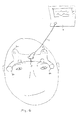
- the system according to the present invention comprises an electrode array 1 connected to a monitor 2 by a cable 4.
- the electrode array 1 has been attached onto the forehead of the patient as shown in Figure 1.
- the electrode array 1 transmits biopotential signals from the forehead of the patient to the monitor 2, which carries out signal processing and displays EEG, FEMG and EM data in desired form.
- the data obtained can also be stored for future use.
- the electrode array 1 shown in Figure 1 comprises five electrodes, ie. the first electrode 5, the second electrode 6, the third electrode 7, the fourth electrode 8 and the fifth electrode 9.
- the first electrode 5 and the third electrode 7 are used to detect phasic and tonic activation of facial muscles intended for expression of painful mimic responses (corrugator, procerus, frontalis and orbicularis oculi muscles), the FEMG signal.
- the first and the second electrodes detect also some EEG related signal.
- the second electrode 6 and the fourth electrode 8 are used to detect cortical activity (EEG) of frontal lobe from the hairless fronto-lateral area and only some FEMG related signal.
- the fifth electrode 9 is a ground electrode.
- the first electrode 5 is positioned above an eyebrow of the patient near frontalis and orbicularis muscles, advantageously directly above an eyebrow in vertical line with the eye.
- the second electrode 6 is positioned to the same cortical hemisphere as the first electrode 5.
- the second electrode 6 is positioned above the first electrode 5 advantageously as far as possible from the first electrode 5 on the hairless fronto-lateral area of the patient.
- the third electrode 7 is positioned directly above the other eyebrow, when compared to the first electrode 5, in vertical line with the eye.
- the third electrode 7 is thus positioned at the opposite hemisphere when compared to the first electrode 5.
- the fourth electrode 8 is positioned to the same cortical hemisphere as the third electrode 7.
- the fourth electrode 8 is positioned above the third electrode 7 advantageously as far as possible from the third electrode 7 on the hairless fronto-lateral area of the patient.
- the fifth electrode 9 can be positioned to any area of the patient advantageously having bone immediately under the skin, for example on the forehead area or on the area behind an ear of the patient. It is also advantageous to place the electrodes of a hairless area of the patient's skin. In the embodiment of Figure 1 the fifth electrode is positioned at the centre of the forehead of the patient. It is very advantageous to place the fifth electrode 9 essentially at the centre of the area defined by the four other electrodes 5, 6, 7 and 8. This gives an opportunity to optimize Common Mode Rejection Ratio (CMRR) of the measured signal.
- CMRR Common Mode Rejection Ratio
- the five-electrode system described above and placed according to the basic idea of the present invention offers two different principles of operation to measure biopotential signals from the patient. Said two principles are shown in montages shown in Figures 3 and 4.
- the first montage shown in Figure 3 offers a simple solution to distinguish EEG, FEMG and EM signals from each other.
- a biopotential with relatively strong FEMG component is measured between the first electrode 5 and the second electrode 7, which is called the FEMG channel 10.
- a biopotential with relatively strong EEG component is measured between the second electrode 6 and the fourth electrode 8, which is called the EEG channel 11.
- the EEG and FEMG components can be identified from the two signals for example by spectral analysis. Eye movements in all directions have identical morphology in both channels, but they contribute to higher amplitudes in the FEMG channel. Eye movements can be detected and removed for example by analyzing the correlation between the two channels.
- the second montage shown in Figure 4 offers a choice to measure the biopotential signals from both cortical hemispheres for functional comparison. The measurement may provide diagnostic information to detect brain injuries and epileptic discharges of critical care patients.
- the first biopotential signal 12 is measured between the first electrode 5 and the second electrode 6, and the second biopotential signal 13 is measured between the third electrode 7 and the fourth electrode 8.
- EEG and FEMG signals are superimposed on top of each other. Horizontal and vertical eye movements have identical morphology in both channels, whereas diagonal eye movements have different morphologies.
- the second montage shown in Figure 4 is therefore somewhat less sensitive in detecting eye movements then the first montage shown in Figure 3.
- the second montage does not discriminate between EEG and FEMG components as accurately as the first montage.
- the first montage is optimized to assess the level of sedation and the second montage is purposeful to detect non-symmetries between hemispheres, which indicates brain injuries or epileptic discharges.
- One solution might be eg. to switch between the montages in every five minutes.
- Another possibility is to use the first montage and switch to the second montage only when brain injuries or epileptic discharges are present. The second montage is then purposeful to localize phenomena.
- the second embodiment of the present invention includes also a solution to identify directions of the eye movements.
- the second embodiment is shown in Figure 2.
- the second electrode 6 is positioned to the temple of the patient for example to the area between an eye and an ear advantageously at eye level anterior to an ear, at the same side of the head as the first electrode 5.
- the first electrode 5 and the third electrode 7 are positioned in the same way as described in connection with the first embodiment of the invention described in Figure 1.
- the fourth electrode 8 is positioned to the temple of the patient for example to the area between an eye and an ear advantageously at eye level anterior to an ear at the same side of the head as the third electrode 7.
- EEG, FEMG and EM signals are measured with two bipolar montages shown in Figure 5.
- the first electrode 5 and the second electrode 6 are used to measure EEG from one hemisphere 14, the first electrode is a positive pole and the second electrode is a negative pole.
- the third electrode 7 and the fourth electrode 8 are used to measure EEG from the other hemisphere 15.
- the third electrode is a positive pole and the fourth electrode is a negative pole.
- Both bipolar montages measure also FEMG and EM.
- the fifth electrode 9, ie. the ground electrode is placed at the middle area between the first 5 and the third electrode 7.
- the fifth electrode 9 can however be placed otherwise too, for example in the way as described in connection with Figure 1.
- Eye can be modeled as an electrical dipole. Cornea has positive charge and retina has negative charge. When a patient watches up positive charge flows to the forehead, otherwise when a patient watches down negative charge flows to the forehead. When a patient blinks his or her eyes, there is a sudden rise and fall on the voltage at the forehead. This is because eyelid conducts the positive charge of cornea.
- VEM Vertical eye movements
- HEM Horizontal eye movements
- DEM diagonal eye movements
- the embodiment shown in Figure 6 uses an array of seven electrodes. Location of the electrodes are those described in connection with Figures 1 and 2.
- the second electrode is marked with a reference number 6a and the sixth electrode is marked with a reference number 6b.
- the fourth electrode is marked with a reference number 8a and the seventh electrode is marked with a reference number 8b.
- the second electrode 6a corresponds to the second electrode 6 of the embodiment shown in Figure 1 and the sixth electrode 6b corresponds to the second electrode 6 shown in the embodiment of Figure 2.
- the fourth electrode 8a corresponds to the fourth electrode 8 of the embodiment shown in Figure 1 and the seventh electrode corresponds to the fourth electrode 8 of Figure 2.
- the system shown in Figure 6 is a combination of the systems shown in Figures 1 and 2.
- the fifth electrode ie. the ground electrode is placed at the centre of the area defined by the first 5, the second 6a, the third 7 and the fourth electrode 8a in the embodiment of Figure 6.
- the fifth electrode can however be otherwise too in the way as described in connection with Figures 1 and 2.
- FIG. 6 shows one possible montage in phantom lines.
- Bipolar montage between electrodes 6a and 8a is used to measure EEG.
- Bipolar montages between electrodes 5 and 6b and between electrodes 7 and 8b are used to measure EMG and eye movements and to identify nonsymmetries between hemispheres.
- Figure 8 shows another possible montage in phantom lines.
- Bipolar montage between electrodes 5 and 7 is used to measure EMG.
- Bipolar montages between electrodes 6a and 6b and between electrodes 8a and 8b are used to measure EEG and eye movements and to identify nonsymmetries between hemispheres.
Landscapes
- Health & Medical Sciences (AREA)
- Life Sciences & Earth Sciences (AREA)
- Medical Informatics (AREA)
- Biophysics (AREA)
- Pathology (AREA)
- Engineering & Computer Science (AREA)
- Biomedical Technology (AREA)
- Heart & Thoracic Surgery (AREA)
- Physics & Mathematics (AREA)
- Molecular Biology (AREA)
- Surgery (AREA)
- Animal Behavior & Ethology (AREA)
- General Health & Medical Sciences (AREA)
- Public Health (AREA)
- Veterinary Medicine (AREA)
- Anesthesiology (AREA)
- Measurement And Recording Of Electrical Phenomena And Electrical Characteristics Of The Living Body (AREA)
- Eye Examination Apparatus (AREA)
Abstract
Description
| Type of EM | Direction | Effect to voltage on left channel | Effect to voltage on right channel |
| VEM | Up | Up | Up |
| Down | Down | Down | |
| HEM | Right to left | Up | Down |
| Left to right | Down | Up | |
| DEM | Down left to up right | Up | No effect |
| Up left to down right | No effect | Down | |
| Down right to up left | No effect | Up | |
| Up right to down left | Down | No effect |
Claims (23)
- Method of positioning electrodes in an electrode array comprising at least five electrodes for central nervous system (CNS) monitoring from the forehead of a patient's head, the method comprising the steps of:positioning a first electrode above the eyebrows near frontalis and orbicularis muscles of the patient;positioning a second electrode above the first electrode the fronto-lateral area of the frontal lobe of the patient and on the same hemisphere as the first electrode;positioning a third electrode above the eyebrows near frontalis and orbicularis muscles of the patient at the opposite hemisphere when compared to the first electrode;positioning a fourth electrode above the third electrode on the fronto-lateral area of the frontal lobe of the patient and on the same hemisphere as the third electrode; andpositioning a fifth electrode on the patient's skin.
- The method of claim 1 wherein the second electrode is positioned as far as possible from the first electrode and the fourth electrode is positioned as far as possible from the third electrode.
- The method of claim 1 wherein the fifth electrode is positioned on the area of the patient's skin having bone immediately under the skin.
- The method of claims 2 and 3 wherein the areas on which the second, the fourth and the fifth electrode are positioned are hairless areas.
- The method of claim 1, wherein the first, second, third and fourth electrodes are measuring electrodes and the fifth electrode is a ground electrode.
- The method of claim 5, wherein FEMG is measured with bipolar connection between the first and the third electrode.
- The method of claim 5, wherein EEG is measured with bipolar connection between the second and the fourth electrode.
- The method of claim 5, wherein EEG from one hemisphere is measured between the first and the second electrode, and EEG from the other hemisphere is measured between the third and the fourth electrode.
- The method of claim 1 wherein the fifth electrode is positioned on the head area of the patient.
- The method of claim 9 wherein the fifth electrode is positioned at the centre of the area defined by the above mentioned four electrodes.
- Method of positioning electrodes in an electrode array comprising at least five electrodes for central nervous system (CNS) monitoring from the forehead of a patient's head, the method comprising the steps of:positioning a first electrode above the eyebrows near frontalis and orbicularis muscles of the patient;positioning a second electrode to the temple of the patient at the same side of the head as the first electrode;positioning a third electrode above the eyebrows near frontalis and orbicularis muscles of the patient at the opposite hemisphere when compared to the first electrode;positioning a fourth electrode to the temple of the patient at the same side of the head as the third electrode, andpositioning a fifth electrode on the patient's skin.
- The method of claim 11 wherein the temple is the area between and eye and an ear.
- The method of claim 12 wherein the area is at eye level anterior of the ear.
- The method of claim 11 wherein the fifth electrode is positioned on the area of the patient's skin having bone immediately under the skin.
- The method of claim 14 wherein the fifth electrode is positioned on the head area of the patient.
- The method of claim 15 wherein the fifth electrode is positioned at the middle area between the first and the third electrode.
- The method of claim 11 wherein EEG is measured from one hemisphere by using the first and the second electrode, and EEG is measured from the other hemisphere by using the third and the fourth electrode.
- Method of positioning electrodes in an electrode array comprising at least seven electrodes for central nervous system (CNS) monitoring from the forehead of a patient's head, the method comprising the steps of:positioning a first electrode above the eyebrows near frontalis and orbicularis muscles of the patient;positioning a second electrode above the first electrode on the fronto-lateral area of the frontal lobe of the patient and on the same hemisphere as the first electrode;positioning a third electrode above the eyebrows near frontalis and orbicularis muscles of the patient at the opposite hemisphere when compared to the first electrode;positioning a fourth electrode above the third electrode on the fronto-lateral area of the frontal lobe of the patient and on the same hemisphere as the third electrode;positioning a fifth electrode on the patient's skin;positioning a sixth electrode to the temple of the patient at the same side of the head as the first electrode, andpositioning a seventh electrode to the temple of the patient's head at the same side of the head as the third electrode.
- The method of claim 18 wherein the temple is the area between and eye and an ear.
- The method of claim 19 wherein the area is at eye level anterior of the ear.
- The method of claim 18 wherein the fifth electrode is positioned on the area of the patient's skin having bone immediately under the skin.
- The method of claim 21 wherein the fifth electrode is positioned on the head area of the patient.
- The method of claim 22 wherein the fifth electrode is positioned at the centre area defined by the first, the second, the third and the fourth electrodes.
Applications Claiming Priority (2)
| Application Number | Priority Date | Filing Date | Title |
|---|---|---|---|
| US10/612,828 US6950698B2 (en) | 2003-07-02 | 2003-07-02 | Method of positioning electrodes for central nervous system monitoring |
| US612828 | 2003-07-02 |
Publications (2)
| Publication Number | Publication Date |
|---|---|
| EP1493383A2 true EP1493383A2 (en) | 2005-01-05 |
| EP1493383A3 EP1493383A3 (en) | 2005-01-12 |
Family
ID=33435465
Family Applications (1)
| Application Number | Title | Priority Date | Filing Date |
|---|---|---|---|
| EP04102678A Ceased EP1493383A3 (en) | 2003-07-02 | 2004-06-14 | Method of positioning electrodes for central nervous system monitoring |
Country Status (2)
| Country | Link |
|---|---|
| US (1) | US6950698B2 (en) |
| EP (1) | EP1493383A3 (en) |
Cited By (6)
| Publication number | Priority date | Publication date | Assignee | Title |
|---|---|---|---|---|
| EP1800600A1 (en) * | 2005-12-22 | 2007-06-27 | General Electric Company | Electrode configuration for central nervous system monitoring |
| EP2090225A1 (en) * | 2008-02-15 | 2009-08-19 | AGS - Medicare GmbH | Assembly for measuring EEG, EOG and EMG |
| RU2436503C1 (en) * | 2010-05-24 | 2011-12-20 | Учреждение Российской Академии Медицинских Наук Научно-исследовательский институт экспериментальной медицины Северо-западного отделения РАМН (НИИЭМ СЗО РАМН) | Method for detection of dysfunction of hemoliquorodynamics of cerebrum |
| EP2068705B1 (en) * | 2006-09-25 | 2015-11-11 | Koninklijke Philips N.V. | Device for ambulatory monitoring of brain activity |
| US9770184B2 (en) | 2012-11-12 | 2017-09-26 | Bittium Biosignals Oy | Arrangement and method for carrying out electrode measurements |
| US11684305B2 (en) | 2018-06-02 | 2023-06-27 | Seyedhesam Sadeghian-Motahar | Electrode array configuration on a flexible substrate for electro-oculogram recording |
Families Citing this family (68)
| Publication number | Priority date | Publication date | Assignee | Title |
|---|---|---|---|---|
| US7130673B2 (en) * | 2003-04-08 | 2006-10-31 | Instrumentarium Corp. | Method of positioning electrodes for central nervous system monitoring and sensing pain reactions of a patient |
| US7496400B2 (en) * | 2003-10-17 | 2009-02-24 | Ge Healthcare Finland Oy | Sensor arrangement |
| US20060258930A1 (en) * | 2004-05-18 | 2006-11-16 | Jianping Wu | Device for use in sleep stage determination using frontal electrodes |
| US20090105577A1 (en) * | 2006-05-18 | 2009-04-23 | Jianping Wu | Device For Detecting Electrical Potentials Using Frontal Electrodes |
| US20080221422A1 (en) * | 2007-03-08 | 2008-09-11 | General Electric Company | Sensor measurement system having a modular electrode array and method therefor |
| US8484081B2 (en) | 2007-03-29 | 2013-07-09 | The Nielsen Company (Us), Llc | Analysis of marketing and entertainment effectiveness using central nervous system, autonomic nervous system, and effector data |
| US9402558B2 (en) * | 2007-04-05 | 2016-08-02 | New York University | System and method for pain detection and computation of a pain quantification index |
| EP2142082A4 (en) | 2007-05-01 | 2015-10-28 | Neurofocus Inc | NEUROINFORMATIC REFERENCE SYSTEM |
| US9886981B2 (en) | 2007-05-01 | 2018-02-06 | The Nielsen Company (Us), Llc | Neuro-feedback based stimulus compression device |
| US8392253B2 (en) | 2007-05-16 | 2013-03-05 | The Nielsen Company (Us), Llc | Neuro-physiology and neuro-behavioral based stimulus targeting system |
| US8494905B2 (en) | 2007-06-06 | 2013-07-23 | The Nielsen Company (Us), Llc | Audience response analysis using simultaneous electroencephalography (EEG) and functional magnetic resonance imaging (fMRI) |
| EP2170161B1 (en) | 2007-07-30 | 2018-12-05 | The Nielsen Company (US), LLC. | Neuro-response stimulus and stimulus attribute resonance estimator |
| US8392254B2 (en) | 2007-08-28 | 2013-03-05 | The Nielsen Company (Us), Llc | Consumer experience assessment system |
| US8386313B2 (en) | 2007-08-28 | 2013-02-26 | The Nielsen Company (Us), Llc | Stimulus placement system using subject neuro-response measurements |
| US8635105B2 (en) | 2007-08-28 | 2014-01-21 | The Nielsen Company (Us), Llc | Consumer experience portrayal effectiveness assessment system |
| US8392255B2 (en) | 2007-08-29 | 2013-03-05 | The Nielsen Company (Us), Llc | Content based selection and meta tagging of advertisement breaks |
| US8494610B2 (en) | 2007-09-20 | 2013-07-23 | The Nielsen Company (Us), Llc | Analysis of marketing and entertainment effectiveness using magnetoencephalography |
| US20090083129A1 (en) | 2007-09-20 | 2009-03-26 | Neurofocus, Inc. | Personalized content delivery using neuro-response priming data |
| US7983757B2 (en) * | 2007-10-26 | 2011-07-19 | Medtronic, Inc. | Medical device configuration based on sensed brain signals |
| US8548558B2 (en) * | 2008-03-06 | 2013-10-01 | Covidien Lp | Electrode capable of attachment to a garment, system, and methods of manufacturing |
| US20100069780A1 (en) * | 2008-03-19 | 2010-03-18 | Ocz Technology Group, Inc. | Method and apparatus for using biopotentials for simultaneous multiple control functions in computer systems |
| US9039631B2 (en) | 2008-10-09 | 2015-05-26 | Neuro Kinetics | Quantitative, non-invasive, clinical diagnosis of traumatic brain injury using VOG device for neurologic testing |
| US10398309B2 (en) | 2008-10-09 | 2019-09-03 | Neuro Kinetics, Inc. | Noninvasive rapid screening of mild traumatic brain injury using combination of subject's objective oculomotor, vestibular and reaction time analytic variables |
| US8868216B2 (en) * | 2008-11-21 | 2014-10-21 | Covidien Lp | Electrode garment |
| US8464288B2 (en) | 2009-01-21 | 2013-06-11 | The Nielsen Company (Us), Llc | Methods and apparatus for providing personalized media in video |
| US8270814B2 (en) | 2009-01-21 | 2012-09-18 | The Nielsen Company (Us), Llc | Methods and apparatus for providing video with embedded media |
| US9357240B2 (en) | 2009-01-21 | 2016-05-31 | The Nielsen Company (Us), Llc | Methods and apparatus for providing alternate media for video decoders |
| US20100250325A1 (en) | 2009-03-24 | 2010-09-30 | Neurofocus, Inc. | Neurological profiles for market matching and stimulus presentation |
| US8655437B2 (en) | 2009-08-21 | 2014-02-18 | The Nielsen Company (Us), Llc | Analysis of the mirror neuron system for evaluation of stimulus |
| US10987015B2 (en) | 2009-08-24 | 2021-04-27 | Nielsen Consumer Llc | Dry electrodes for electroencephalography |
| US8756657B2 (en) * | 2009-09-29 | 2014-06-17 | Ebay Inc. | Mobile or user device authentication and tracking |
| US8209224B2 (en) | 2009-10-29 | 2012-06-26 | The Nielsen Company (Us), Llc | Intracluster content management using neuro-response priming data |
| US9560984B2 (en) | 2009-10-29 | 2017-02-07 | The Nielsen Company (Us), Llc | Analysis of controlled and automatic attention for introduction of stimulus material |
| US20110106750A1 (en) | 2009-10-29 | 2011-05-05 | Neurofocus, Inc. | Generating ratings predictions using neuro-response data |
| US8335715B2 (en) | 2009-11-19 | 2012-12-18 | The Nielsen Company (Us), Llc. | Advertisement exchange using neuro-response data |
| US8335716B2 (en) | 2009-11-19 | 2012-12-18 | The Nielsen Company (Us), Llc. | Multimedia advertisement exchange |
| US8838226B2 (en) * | 2009-12-01 | 2014-09-16 | Neuro Wave Systems Inc | Multi-channel brain or cortical activity monitoring and method |
| EP2531095B1 (en) * | 2010-02-03 | 2018-07-18 | Covidien LP | Combined physiological sensor systems and methods |
| WO2011133548A2 (en) | 2010-04-19 | 2011-10-27 | Innerscope Research, Inc. | Short imagery task (sit) research method |
| US8655428B2 (en) | 2010-05-12 | 2014-02-18 | The Nielsen Company (Us), Llc | Neuro-response data synchronization |
| US8392250B2 (en) | 2010-08-09 | 2013-03-05 | The Nielsen Company (Us), Llc | Neuro-response evaluated stimulus in virtual reality environments |
| US8392251B2 (en) | 2010-08-09 | 2013-03-05 | The Nielsen Company (Us), Llc | Location aware presentation of stimulus material |
| US8396744B2 (en) | 2010-08-25 | 2013-03-12 | The Nielsen Company (Us), Llc | Effective virtual reality environments for presentation of marketing materials |
| EP2621333B1 (en) | 2010-09-28 | 2015-07-29 | Masimo Corporation | Depth of consciousness monitor including oximeter |
| US9775545B2 (en) | 2010-09-28 | 2017-10-03 | Masimo Corporation | Magnetic electrical connector for patient monitors |
| US9569986B2 (en) | 2012-02-27 | 2017-02-14 | The Nielsen Company (Us), Llc | System and method for gathering and analyzing biometric user feedback for use in social media and advertising applications |
| US9292858B2 (en) | 2012-02-27 | 2016-03-22 | The Nielsen Company (Us), Llc | Data collection system for aggregating biologically based measures in asynchronous geographically distributed public environments |
| US9451303B2 (en) | 2012-02-27 | 2016-09-20 | The Nielsen Company (Us), Llc | Method and system for gathering and computing an audience's neurologically-based reactions in a distributed framework involving remote storage and computing |
| US8585589B1 (en) * | 2012-08-06 | 2013-11-19 | James Z. Cinberg | Method and associated apparatus for detecting minor traumatic brain injury |
| US8808179B1 (en) * | 2012-08-06 | 2014-08-19 | James Z. Cinberg | Method and associated apparatus for detecting minor traumatic brain injury |
| US9060671B2 (en) | 2012-08-17 | 2015-06-23 | The Nielsen Company (Us), Llc | Systems and methods to gather and analyze electroencephalographic data |
| US9320450B2 (en) | 2013-03-14 | 2016-04-26 | The Nielsen Company (Us), Llc | Methods and apparatus to gather and analyze electroencephalographic data |
| WO2015057709A1 (en) * | 2013-10-14 | 2015-04-23 | Neurovigil, Inc. | Localized collection of biological signals, cursor control in speech-assistance interface based on biological electrical signals and arousal detection based on biological electrical signals |
| US9622702B2 (en) | 2014-04-03 | 2017-04-18 | The Nielsen Company (Us), Llc | Methods and apparatus to gather and analyze electroencephalographic data |
| US10154815B2 (en) | 2014-10-07 | 2018-12-18 | Masimo Corporation | Modular physiological sensors |
| SG11201705499VA (en) * | 2015-01-10 | 2017-08-30 | Deborah Dullen | Method and apparatus for the measurement of autonomic function for the diagnosis and validation of patient treatments and outcomes |
| US9936250B2 (en) | 2015-05-19 | 2018-04-03 | The Nielsen Company (Us), Llc | Methods and apparatus to adjust content presented to an individual |
| US10506974B2 (en) | 2016-03-14 | 2019-12-17 | The Nielsen Company (Us), Llc | Headsets and electrodes for gathering electroencephalographic data |
| KR102054558B1 (en) * | 2016-10-28 | 2019-12-12 | 주식회사 인바디 | Electrodes of anesthetic depth monitoring device |
| WO2019060298A1 (en) | 2017-09-19 | 2019-03-28 | Neuroenhancement Lab, LLC | Method and apparatus for neuroenhancement |
| US11717686B2 (en) | 2017-12-04 | 2023-08-08 | Neuroenhancement Lab, LLC | Method and apparatus for neuroenhancement to facilitate learning and performance |
| US11318277B2 (en) | 2017-12-31 | 2022-05-03 | Neuroenhancement Lab, LLC | Method and apparatus for neuroenhancement to enhance emotional response |
| US12280219B2 (en) | 2017-12-31 | 2025-04-22 | NeuroLight, Inc. | Method and apparatus for neuroenhancement to enhance emotional response |
| US11364361B2 (en) | 2018-04-20 | 2022-06-21 | Neuroenhancement Lab, LLC | System and method for inducing sleep by transplanting mental states |
| CN113382683A (en) | 2018-09-14 | 2021-09-10 | 纽罗因恒思蒙特实验有限责任公司 | System and method for improving sleep |
| US11395615B2 (en) * | 2019-04-17 | 2022-07-26 | Bose Corporation | Fatigue and drowsiness detection |
| US11786694B2 (en) | 2019-05-24 | 2023-10-17 | NeuroLight, Inc. | Device, method, and app for facilitating sleep |
| CN113143676B (en) * | 2020-12-15 | 2023-04-11 | 天津大学 | Control method of external limb finger based on brain-muscle-electricity cooperation |
Family Cites Families (13)
| Publication number | Priority date | Publication date | Assignee | Title |
|---|---|---|---|---|
| WO1993002616A1 (en) | 1991-08-09 | 1993-02-18 | Srd Shorashim Medical, Ltd. | Apparatus for mounting electrodes |
| US5291888A (en) * | 1991-08-26 | 1994-03-08 | Electrical Geodesics, Inc. | Head sensor positioning network |
| AU667199B2 (en) * | 1991-11-08 | 1996-03-14 | Physiometrix, Inc. | EEG headpiece with disposable electrodes and apparatus and system and method for use therewith |
| JP2548652B2 (en) | 1991-12-11 | 1996-10-30 | セーラー万年筆株式会社 | EEG measurement tool |
| US5293187A (en) * | 1992-02-05 | 1994-03-08 | Biocontrol Systems, Inc. | Method and apparatus for eye tracking for convergence and strabismus measurement |
| US6233472B1 (en) * | 1995-06-06 | 2001-05-15 | Patient Comfort, L.L.C. | Electrode assembly and method for signaling a monitor |
| US5772591A (en) * | 1995-06-06 | 1998-06-30 | Patient Comfort, Inc. | Electrode assembly for signaling a monitor |
| US6394953B1 (en) * | 2000-02-25 | 2002-05-28 | Aspect Medical Systems, Inc. | Electrode array system for measuring electrophysiological signals |
| US6032065A (en) * | 1997-07-21 | 2000-02-29 | Nellcor Puritan Bennett | Sensor mask and method of making same |
| US20020019588A1 (en) | 2000-06-23 | 2002-02-14 | Marro Dominic P. | Frontal electrode array for patient EEG signal acquisition |
| US6757558B2 (en) * | 2000-07-06 | 2004-06-29 | Algodyne, Ltd. | Objective pain measurement system and method |
| US6801803B2 (en) | 2000-10-16 | 2004-10-05 | Instrumentarium Corp. | Method and apparatus for determining the cerebral state of a patient with fast response |
| US6728564B2 (en) | 2001-07-03 | 2004-04-27 | Instrumentarium Corp. | Configurable sensor system for measuring biopotentials |
-
2003
- 2003-07-02 US US10/612,828 patent/US6950698B2/en not_active Expired - Fee Related
-
2004
- 2004-06-14 EP EP04102678A patent/EP1493383A3/en not_active Ceased
Cited By (7)
| Publication number | Priority date | Publication date | Assignee | Title |
|---|---|---|---|---|
| EP1800600A1 (en) * | 2005-12-22 | 2007-06-27 | General Electric Company | Electrode configuration for central nervous system monitoring |
| US7599735B2 (en) | 2005-12-22 | 2009-10-06 | General Electric Company | Electrode configuration for central nervous system monitoring |
| EP2068705B1 (en) * | 2006-09-25 | 2015-11-11 | Koninklijke Philips N.V. | Device for ambulatory monitoring of brain activity |
| EP2090225A1 (en) * | 2008-02-15 | 2009-08-19 | AGS - Medicare GmbH | Assembly for measuring EEG, EOG and EMG |
| RU2436503C1 (en) * | 2010-05-24 | 2011-12-20 | Учреждение Российской Академии Медицинских Наук Научно-исследовательский институт экспериментальной медицины Северо-западного отделения РАМН (НИИЭМ СЗО РАМН) | Method for detection of dysfunction of hemoliquorodynamics of cerebrum |
| US9770184B2 (en) | 2012-11-12 | 2017-09-26 | Bittium Biosignals Oy | Arrangement and method for carrying out electrode measurements |
| US11684305B2 (en) | 2018-06-02 | 2023-06-27 | Seyedhesam Sadeghian-Motahar | Electrode array configuration on a flexible substrate for electro-oculogram recording |
Also Published As
| Publication number | Publication date |
|---|---|
| US20050004489A1 (en) | 2005-01-06 |
| EP1493383A3 (en) | 2005-01-12 |
| US6950698B2 (en) | 2005-09-27 |
Similar Documents
| Publication | Publication Date | Title |
|---|---|---|
| US6950698B2 (en) | Method of positioning electrodes for central nervous system monitoring | |
| US7130673B2 (en) | Method of positioning electrodes for central nervous system monitoring and sensing pain reactions of a patient | |
| US7215994B2 (en) | Monitoring the neurological state of a patient | |
| Kane et al. | A revised glossary of terms most commonly used by clinical electroencephalographers and updated proposal for the report format of the EEG findings. Revision 2017 | |
| Whitham et al. | Scalp electrical recording during paralysis: quantitative evidence that EEG frequencies above 20 Hz are contaminated by EMG | |
| US6067467A (en) | EEG operative and post-operative patient monitoring method | |
| US8380316B2 (en) | Transcranial stimulation device and method based on electrophysiological testing | |
| US7570991B2 (en) | Method for real time attitude assessment | |
| US5699808A (en) | EEG operative and post-operative patient monitoring system and method | |
| Kearse Jr et al. | Somatosensory evoked potentials sensitivity relative to electroencephalography for cerebral ischemia during carotid endarterectomy. | |
| EP1854404B1 (en) | Monitoring of the state of the central nervous system of a subject | |
| Pihko et al. | Somatosensory evoked potentials and magnetic fields elicited by tactile stimulation of the hand during active and quiet sleep in newborns | |
| Chatrian et al. | IFCN recommended standards for electrophysiologic monitoring in comatose and other unresponsive states. Report of an IFCN committee | |
| CN101677775A (en) | System and method for pain detection and computation of a pain quantification index | |
| EP1757226B1 (en) | Measurement of responsiveness of a patient under anaesthesia | |
| De La Torre et al. | Somatosensory evoked potentials for the prognosis of coma in humans | |
| EP1516581B1 (en) | A combined passive and active neuromonitoring device | |
| Mantri et al. | A survey: fundamental of EEG | |
| US8219187B2 (en) | Method and apparatus for providing improved assessment of a physiological condition of a patient | |
| Nahiyan et al. | Origin and dynamics of biomedical signals | |
| Couture et al. | Monitoring responsiveness during anaesthesia | |
| García et al. | The Sensors for stress detection: first analysis | |
| BOOK | SREE CHITRA TIRUNAL INSTITUTE FOR MEDICAL SCIENCES &TECHNOLOGY (SCTIMST) | |
| Mohammed Fuad | Logbook-NeuroTechnology | |
| Arya | LOG BOOK |
Legal Events
| Date | Code | Title | Description |
|---|---|---|---|
| PUAI | Public reference made under article 153(3) epc to a published international application that has entered the european phase |
Free format text: ORIGINAL CODE: 0009012 |
|
| PUAL | Search report despatched |
Free format text: ORIGINAL CODE: 0009013 |
|
| AK | Designated contracting states |
Kind code of ref document: A2 Designated state(s): AT BE BG CH CY CZ DE DK EE ES FI FR GB GR HU IE IT LI LU MC NL PL PT RO SE SI SK TR |
|
| AX | Request for extension of the european patent |
Extension state: AL HR LT LV MK |
|
| AK | Designated contracting states |
Kind code of ref document: A3 Designated state(s): AT BE BG CH CY CZ DE DK EE ES FI FR GB GR HU IE IT LI LU MC NL PL PT RO SE SI SK TR |
|
| AX | Request for extension of the european patent |
Extension state: AL HR LT LV MK |
|
| 17P | Request for examination filed |
Effective date: 20050526 |
|
| AKX | Designation fees paid |
Designated state(s): AT BE BG CH CY CZ DE DK EE ES FI FR GB GR HU IE IT LI LU MC NL PL PT RO SE SI SK TR |
|
| 17Q | First examination report despatched |
Effective date: 20061002 |
|
| STAA | Information on the status of an ep patent application or granted ep patent |
Free format text: STATUS: THE APPLICATION HAS BEEN REFUSED |
|
| 18R | Application refused |
Effective date: 20100731 |