EP1516581B1 - A combined passive and active neuromonitoring device - Google Patents
A combined passive and active neuromonitoring device Download PDFInfo
- Publication number
- EP1516581B1 EP1516581B1 EP04254377A EP04254377A EP1516581B1 EP 1516581 B1 EP1516581 B1 EP 1516581B1 EP 04254377 A EP04254377 A EP 04254377A EP 04254377 A EP04254377 A EP 04254377A EP 1516581 B1 EP1516581 B1 EP 1516581B1
- Authority
- EP
- European Patent Office
- Prior art keywords
- patient
- active
- sedation
- sensor
- passive
- Prior art date
- Legal status (The legal status is an assumption and is not a legal conclusion. Google has not performed a legal analysis and makes no representation as to the accuracy of the status listed.)
- Active
Links
- 210000001061 forehead Anatomy 0.000 claims description 9
- 239000000853 adhesive Substances 0.000 claims description 3
- 230000001070 adhesive effect Effects 0.000 claims description 3
- 238000012544 monitoring process Methods 0.000 abstract description 85
- 206010039897 Sedation Diseases 0.000 abstract description 34
- 230000036280 sedation Effects 0.000 abstract description 34
- 238000000034 method Methods 0.000 abstract description 25
- 230000001629 suppression Effects 0.000 abstract description 5
- 238000000537 electroencephalography Methods 0.000 description 27
- 230000004044 response Effects 0.000 description 16
- 206010002091 Anaesthesia Diseases 0.000 description 13
- 230000037005 anaesthesia Effects 0.000 description 13
- 210000004556 brain Anatomy 0.000 description 11
- 238000005259 measurement Methods 0.000 description 7
- 230000000694 effects Effects 0.000 description 4
- 230000006996 mental state Effects 0.000 description 4
- 230000003925 brain function Effects 0.000 description 3
- 239000003814 drug Substances 0.000 description 3
- 229940079593 drug Drugs 0.000 description 3
- 230000000763 evoking effect Effects 0.000 description 3
- 239000000463 material Substances 0.000 description 3
- 238000012806 monitoring device Methods 0.000 description 3
- 239000000758 substrate Substances 0.000 description 3
- 208000032041 Hearing impaired Diseases 0.000 description 2
- 230000008901 benefit Effects 0.000 description 2
- 230000001054 cortical effect Effects 0.000 description 2
- 230000007423 decrease Effects 0.000 description 2
- 230000001537 neural effect Effects 0.000 description 2
- 239000004033 plastic Substances 0.000 description 2
- 239000004417 polycarbonate Substances 0.000 description 2
- 229920000515 polycarbonate Polymers 0.000 description 2
- 230000008569 process Effects 0.000 description 2
- 238000012545 processing Methods 0.000 description 2
- 210000003625 skull Anatomy 0.000 description 2
- 230000002269 spontaneous effect Effects 0.000 description 2
- 230000007704 transition Effects 0.000 description 2
- 230000002618 waking effect Effects 0.000 description 2
- 238000012935 Averaging Methods 0.000 description 1
- 206010021118 Hypotonia Diseases 0.000 description 1
- 239000012790 adhesive layer Substances 0.000 description 1
- 230000003444 anaesthetic effect Effects 0.000 description 1
- 230000036592 analgesia Effects 0.000 description 1
- 210000003403 autonomic nervous system Anatomy 0.000 description 1
- 210000000988 bone and bone Anatomy 0.000 description 1
- 230000007177 brain activity Effects 0.000 description 1
- 210000000133 brain stem Anatomy 0.000 description 1
- 238000003759 clinical diagnosis Methods 0.000 description 1
- 239000011248 coating agent Substances 0.000 description 1
- 238000000576 coating method Methods 0.000 description 1
- 239000004020 conductor Substances 0.000 description 1
- 230000003247 decreasing effect Effects 0.000 description 1
- 230000001419 dependent effect Effects 0.000 description 1
- 208000037765 diseases and disorders Diseases 0.000 description 1
- 230000004424 eye movement Effects 0.000 description 1
- 230000006870 function Effects 0.000 description 1
- 210000003128 head Anatomy 0.000 description 1
- 230000000147 hypnotic effect Effects 0.000 description 1
- 230000001771 impaired effect Effects 0.000 description 1
- 230000010354 integration Effects 0.000 description 1
- 238000011835 investigation Methods 0.000 description 1
- 208000028867 ischemia Diseases 0.000 description 1
- 230000007774 longterm Effects 0.000 description 1
- 238000000691 measurement method Methods 0.000 description 1
- 239000002991 molded plastic Substances 0.000 description 1
- 210000003205 muscle Anatomy 0.000 description 1
- 230000036640 muscle relaxation Effects 0.000 description 1
- 210000000715 neuromuscular junction Anatomy 0.000 description 1
- 230000010355 oscillation Effects 0.000 description 1
- 230000002980 postoperative effect Effects 0.000 description 1
- 238000011002 quantification Methods 0.000 description 1
- 238000011160 research Methods 0.000 description 1
- 239000007787 solid Substances 0.000 description 1
- 230000000638 stimulation Effects 0.000 description 1
- 238000001356 surgical procedure Methods 0.000 description 1
- 230000001360 synchronised effect Effects 0.000 description 1
- 210000001519 tissue Anatomy 0.000 description 1
- 230000000472 traumatic effect Effects 0.000 description 1
- 230000000007 visual effect Effects 0.000 description 1
- 230000001755 vocal effect Effects 0.000 description 1
- 239000000080 wetting agent Substances 0.000 description 1
Images

Classifications
-
- A—HUMAN NECESSITIES
- A61—MEDICAL OR VETERINARY SCIENCE; HYGIENE
- A61B—DIAGNOSIS; SURGERY; IDENTIFICATION
- A61B5/00—Measuring for diagnostic purposes; Identification of persons
- A61B5/48—Other medical applications
- A61B5/4821—Determining level or depth of anaesthesia
-
- A—HUMAN NECESSITIES
- A61—MEDICAL OR VETERINARY SCIENCE; HYGIENE
- A61B—DIAGNOSIS; SURGERY; IDENTIFICATION
- A61B5/00—Measuring for diagnostic purposes; Identification of persons
- A61B5/24—Detecting, measuring or recording bioelectric or biomagnetic signals of the body or parts thereof
- A61B5/316—Modalities, i.e. specific diagnostic methods
- A61B5/369—Electroencephalography [EEG]
- A61B5/377—Electroencephalography [EEG] using evoked responses
- A61B5/38—Acoustic or auditory stimuli
-
- A—HUMAN NECESSITIES
- A61—MEDICAL OR VETERINARY SCIENCE; HYGIENE
- A61B—DIAGNOSIS; SURGERY; IDENTIFICATION
- A61B5/00—Measuring for diagnostic purposes; Identification of persons
- A61B5/24—Detecting, measuring or recording bioelectric or biomagnetic signals of the body or parts thereof
- A61B5/25—Bioelectric electrodes therefor
- A61B5/279—Bioelectric electrodes therefor specially adapted for particular uses
- A61B5/28—Bioelectric electrodes therefor specially adapted for particular uses for electrocardiography [ECG]
- A61B5/282—Holders for multiple electrodes
-
- A—HUMAN NECESSITIES
- A61—MEDICAL OR VETERINARY SCIENCE; HYGIENE
- A61B—DIAGNOSIS; SURGERY; IDENTIFICATION
- A61B5/00—Measuring for diagnostic purposes; Identification of persons
- A61B5/24—Detecting, measuring or recording bioelectric or biomagnetic signals of the body or parts thereof
- A61B5/25—Bioelectric electrodes therefor
- A61B5/279—Bioelectric electrodes therefor specially adapted for particular uses
- A61B5/291—Bioelectric electrodes therefor specially adapted for particular uses for electroencephalography [EEG]
Definitions
- the present invention relates to a sensor for obtaining electrophysiological biopotential signals, such as EEG or EMG signals. More specifically, the present invention relates to a unitary sensor that utilizes passive neuromonitoring during deep levels of sedation and active neuromonitoring during low levels of sedation and consciousness.
- Neuromonitoring is a subfield of clinical patient monitoring focused on measuring various aspects of brain function and changes in the brain function caused by drugs commonly used to induce and maintain anesthesia in the operation room or sedation in patients under critical or intensive care.
- Electroencephalography is a well established method for assessing brain activity by recording and analyzing the weak biosignals generated in the cortex of the brain with electrodes attached on the skin of the skull surface.
- EEG has been in wide use for decades in basic research of the neural systems of the brain as well as in the clinical diagnosis of various neurophysiological diseases and disorders.
- EEG signals for the objective quantification of the brain function for the purpose of determining the level of consciousness.
- the basic idea is to automatically detect if the subject or patient is asleep or awake. Specifically, this has become an issue, both scientifically and commercially, in the context of measuring the depth of anesthesia during surgery.
- the modem anesthesia delivery process uses sophisticated techniques combining the balanced use of several drugs for maintaining adequate hypnosis, analgesia, muscle relaxation, suppression of the autonomic nervous system and blockade of the neuromuscular junction.
- Too light an anesthesia or in the worst case the patient waking up in the middle of the operation, may cause a traumatic experience both for the patient and for the anesthesia personnel. Too deep an anesthesia may cause increased perioperative costs through extra use of drugs and time and as well as lengthening the time required for the post-operative care. Too deep of sedation of the ICU patients may also cause complications and prolong the expensive usage time for the intensive care theater.
- the EEG method is also called passive neuromonitoring because it is essentially recording the spontaneous electrical activity of the brain.
- Another measurement mode is labeled active neuromonitoring, in which the responses of the brain to specific external stimuli are under investigation.
- a typical stimulus is a short click of sound, which in turn generates a weak EEG response signals in various parts of the brain typically within a few tens of milliseconds after the click.
- the EEG responses are called Auditory Evoked Potentials (AEP) which are a subset of Event Related Potentials (ERP).
- the stimulus in the ERP method can, for example, be a more complex sound burst or even a visual stimulus such as a light flash.
- the AEP are so weak compared to the background EEG that the stimulus and response have to be repeated at least 200 times to be able to extract the shape of the response curve in a synchronized integration process, in which the background signal of more or less random nature will be cancelled.
- An AEP response is an attenuating oscillation wave of a few swings up and down. All the positive and negative peaks have standardized notations and the parameters of interest are the amplitudes of the wave peaks and their delay from the stimulus time, which is referred to as latency in this context. Qualitatively speaking, when the awareness of the subject decreases, the amplitude of peaks decrease and their latency increases.
- the AEP's can be divided to various groups depending on the latency.
- the brain stem responses appear during the first 10 milliseconds, the early cortical responses from 10 to 80 ms (middle latency AEP's, MLAEP), and the late cortical responses appear from 80 to 1000 ms (long latency AEP's, LLAEP). So, in simple terms, the brain reacts weaker and slower to external stimuli when the awareness is reduced, such as during anesthesia.
- the key difference in the performance capability between these two methods is that the modern passive monitoring devices can reliably cover the whole range of consciousness from awake and fully alert, through the threshold of falling asleep, down to the deepest sedation characterized by EEG suppression where the EEG signal is reduced to a straight line.
- Active monitoring devices are able to accurately differentiate the decreasing levels of awareness only down to the level of falling asleep. After the patient is asleep, the signal disappears and no information is obtained regarding deeper levels of sedation.
- passive monitoring methods are generally more useful when the whole range of the consciousness must be monitored, such as in measuring the adequacy of anesthesia for keeping the patient safely on an optimal level of sleep to prevent inadvertent waking up in the middle of an operation.
- ICU intensive care units
- the current practice is to rely upon a subjective assessment carried out by the care personnel by verbal or tactile prompting with help of standardized scoring tables.
- ICU patients are kept in deep anesthetic levels of sedation during the first days of intensive care. During this period, any measurement method should also work reliably at the deeper levels as well, which is possible only by using the passive method.
- US-A-6167298 discloses devices for monitoring and maintaining an alert state of consciousness in a subject wearing the device.
- the device can be a unitary sensor including at least three electrodes on a base strip.
- An alert mental state is maintained through monitoring of brain wave patterns to detect if a transition from an alert to a non-alert mental state is about to occur, or has occurred. If so, a stimulus, e.g., an audible tone, is provided until such time as an alert mental state, as assessed by brain wave activity, is restored.
- a stimulus e.g., an audible tone
- WO-A-03/57030 discloses a physiological sensor combination which has a flexible substrate configured to attach to a tissue site. Multiple sensors are disposed on the substrate, which generate physiological signals. Each of the signals is responsive to a different physiological parameter. Conductors are carried on the substrate and routed between the sensors and at least one connector. The connector is configured to communicate the physiological signals to at least one monitor, which derives measurements of the parameters.
- US-B-6394953 discloses an array of electrodes which is constructed to allow the user to easily adjust to the correct size of the patient's head.
- the array is self adhesive, pre-gelled and disposable.
- the array fits easily over the temple and forehead areas where EEG signals can be acquired by specially designed monitors for purposes of monitoring a number of bodily phenomena, including but not limited to, depth of anesthesia, and/or ischemia, and burst suppression.
- the array is connected to the monitor via a tab connector that is integral to the disposable device.
- the tab connector is insertible into a reusable connector that is part of a monitoring system.
- a unitary sensor constructed in accordance with the present invention comprises a unitary sensor for detecting biopotential signals on the skin of a patient, the sensor comprising a base strip including at least three electrodes spaced along then length of the base strip, each of the sensors being operable to detect biopotential signals on the skin of the patient; and characterised by an extension strip integrally formed with the base strip and extending from the base strip to a distal end, the extension strip including an acoustic emitter attached to the distal end, and the base strip being configured to be attached to the forehead of the patient and the extension strip extends from the base strip such that the acoustic emitter is positionable in an ear of the patient when the base strip is positioned on the forehead of the patient.
- the acoustic emitter is coupled, through a pair of leads, to the control unit such that the acoustic emitter can be utilized to create acoustic stimuli during active monitoring.
- the acoustic emitter is surrounded by a soft, flexible plug such that the acoustic emitter can be received within the patient's ear.
- the single unitary sensor constructed in accordance with the invention can be utilized for both active monitoring using acoustic stimuli and passive monitoring.
- the present invention can be used in a combined neuromonitoring method and device to measure biopotential signals in sedated ICU patients over the whole range of sedation from being fully alert to the complete suppression of EEG.
- the present invention utilizes an integrated sensor combining an acoustic emitter and multiple EEG electrodes on a single, lightweight disposable component.
- the method utilizes active monitoring during light sedation and passive monitoring during deep sedation with adequate intelligence to handle transition from one mode to another.
- the above device can incorporate a control unit that is coupled to both an active monitoring module and a passive monitoring module.
- the passive monitoring module is utilized to record the spontaneous electrical activity of the brain by monitoring EEG signals.
- the passive monitoring module is particularly desirable in monitoring the level of sedation when a patient is deeply sedated.
- the active monitoring module of the system utilizes external stimuli to induce a weak EEG response signal in various parts of the brain. This response, referred to as auditory evoked potentials (AEP), is particularly desirable in determining the level of sedation when the patient is awake or only moderately sedated.
- the control unit of the present invention selects between the active and passive monitoring modules depending upon the sensed level of sedation. As an illustrative example, the control unit utilizes active monitoring when the patient is at Ramsay levels R1-R3 and utilizes passive monitoring when the patient is at Ramsay levels R4-R6. The control unit displays the output of only the active or passive module depending upon the sensed level of sedation.
- the electrodes are also configured to detect AEP signals when the system is used in an active monitoring mode.
- the single base strip can be utilized during both active and passive monitoring situations.
- the Ramsay Score which is used to signify six different levels of sedation. Listed below is a chart illustrating the six levels of the Ramsay Score and the clinical response of the patient for each level: Sedation Score Clinical Response of the Patient RS 1 Awake/agitated RS 2 Lightly sedated RS 3 Moderately sedated RS 4 Deeply sedated, responds to nonpainful stimuli RS 5 Deeply sedated, responds to painful stimuli RS 6 Deeply sedated, unresponsive to painful stimuli
- AAITM monitor available from Danmeter.
- an auditory stimulus such as a click
- AEP auditory evoked potential
- the criteria for continuing to use active monitoring is typically defined as a minimum amplitude of the relevant AEP peak that is reliably detectable. When the amplitude of the peak gets smaller than an acceptable threshold, which typically occurs between Ramsay levels RS4 and RS5, the active monitoring system no longer becomes reliable.
- the passive monitoring module is particularly desirable for determining the depth of sedation when a patient is in the Ramsay levels R4 to R6, while the active monitoring module is particularly desirable in determining the level of sedation when the patient is in Ramsay levels R1 to R3.
- Fig. 1 thereshown is a general schematic illustration of a system that can be used with the unitary sensor of the present invention.
- the present invention is directed to a combined passive and active neuromonitoring system 10.
- the system 10 generally includes a central control unit 12 connected to both an active monitoring module 14 and a passive monitoring module 16.
- the control unit 12 selects between the active monitoring module 14 and the passive monitoring module 16 depending upon the Ramsay level of sedation and the received EEG signal from the combined sensor 18.
- the combined sensor 18, that will be described in greater detail below, includes both a base strip 20 including multiple electrodes and an extension strip 22 that includes an acoustic emitter that allows the system of the present invention to carry out both active monitoring and passive monitoring by utilizing the same common sensor 18.
- the active monitoring module 14 can be the type of signal processing described in published PCT patent application WO 01/74248 while the passive monitoring module can be the type shown in published PCT patent application WO 02/32305 . It should be understood that other active and passive systems could be utilized while operating within the scope of the present invention.
- the criteria for determining whether to utilize the active monitoring module or the passive monitoring module is determined by a minimum amplitude of the relevant AEP peak that can be reliably detected.
- a threshold value typically occurs when the level of sedation reaches Ramsay levels RS4 and RS5
- the control unit 12 of the system 10 switches over to display the results on display 24 that are obtained by the passive module 16.
- the relevant AEP peak is greater than the threshold value, the control unit 12 displays the results obtained by the active monitoring module 14.
- control unit include software that allows the control unit to monitor some type of threshold value and, based upon the threshold value, select between the active monitoring module 14 and the passive monitoring module 16. The selection of the threshold value can vary depending upon the various active and passive monitoring modules, as well as the software contained within the control unit 12.
- the neuromonitoring system 10 can utilize both the active and passive modes running simultaneously since these two modes do not interfere with each other.
- the control unit 12 typically displays only one of the two results to avoid complicating the already complicated intensive care data environment.
- the passive monitoring module 16 is faster and is able to calculate a result from a time window of between five and fifteen seconds.
- the active monitoring module 14, can generate a sequence of AEP with 256 consecutive repetitions of impulses in approximately two minutes.
- the requirement for a fast response from the active monitoring module 14 is not necessary in monitoring an ICU patient over several days.
- Fig. 2 thereshown is a typical AEP signal 25 from a patient at a sample level of sedation.
- the peak of the signal is measured from the peak 26 (N b ).
- the latency of the signal is measured as the amount of time that has passed from applying the stimulus until the peak 26, as measured by time frame 28 in Fig. 2 . In the example shown in Fig. 2 , this latency period is approximately 45 milliseconds.
- amplitude 30 is measured the peak-to-peak difference between peak 26 (N b ) and peak 27 (P 1 ), as illustrated by amplitude 30.
- the value of the amplitude 30 is not critical, but rather the difference of the amplitude 30 from a baseline is the measured criteria.
- the amplitude 30 and the latency 28 are patient-dependent such that absolute values for these two measurements cannot be used as threshold levels.
- the threshold can be defined based on these relative values.
- the control unit 12 can include an algorithm that is programmed to switch from the active monitoring module 14 to the passive monitoring module 16 when the amplitude 30 has dropped below 20% of its maximum value. If the measurement is used in typical ICU situations during the first days of care when the patient is emerging from deep sedation, the moment when the passive mode indicates the return of consciousness can be used as a criteria to move from the passive monitoring module to the active monitoring module. As discussed previously, the passive monitoring module is preferably used when monitoring a patient in Ramsay levels RS4 to RS6, while active monitoring module 14 is used when the patient is in Ramsay levels RS to RS3.
- control unit 12 When a patient is in a level of sedation between Ramsay level RS3 and Ramsay level RS4, the control unit 12 utilizes software including fuzzy logic that takes into account both the information from the active monitoring module 14 and the passive monitoring module 16 to determine which monitoring mode to use on the display 24.
- system 10 shown in Fig. 1 utilizes both an active monitoring module 14 and a passive monitoring module 16
- the system 10 is preferably utilized with a single sensor 18 developed in accordance with the present invention.
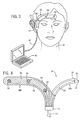
- the sensor 18 of the present invention is shown applied to the forehead of a subject, such as patient 32.
- the sensor 18 has three individual electrodes 34, 36 and 38 that provide a single channel of EEG signal data to the control unit of the monitoring computer 40 through a single cable 42.
- a computer 40 is shown in Fig. 3 , it should be understood that other types of processing components could be utilized to receive the data from cable 42.
- the senor 18 In addition to being able to generate an EEG signal, the sensor 18 also functions as an AEP sensor such that the single sensor 18 can be utilized with both the active and passive monitoring modules.
- the sensor 18 includes an extension strip 22 that extends from the base sensor strip 20 and is received within the patient's ear 44.
- the extension strip 22 is received within the patient's ear 44 to deliver auditory stimuli that are used by the active monitoring module 14 to induce the generation of an AEP signal that can then be sensed by the sensors 34, 36 and 38 placed on the patient's forehead.
- the sensor 18 includes a base sensor strip 20 and an extension strip 22.
- the base strip 20 and the extension strip 22 are formed as a unitary element of injected molded plastic material, such as polycarbonate plastic.
- the sensor 18 includes the common connector 45 connected to the cable 42.
- the base strip 20 includes the individual electrodes 34, 36, and 38, each of which include a lead 46 that extends to the connector 45.
- the leads 46 allow the individual electrodes to communicate to the control unit through the cable 42.
- Each of the electrodes includes an outer surface that can be placed adjacent to the skin of the patient when the sensor and the plurality of electrodes are in use.
- the portions of the base strip 20 not occupied by the electrode areas 34, 36 and 38 are formed to possess a desired degree of flexibility so as to allow the sensor 18 to conform to the contours of the skin of the patient on which the sensor 18 is placed.
- a variety of techniques may be used to render these portions of the base member flexible.
- the portions of the base strip 20 may be sufficiently thin in a direction normal to the surface to render it flexible.
- the thickness of the portions of the base strip 20 may be less than 0.5 millimeters, for example, 0.2 to 0.5 millimeters, or the portions of the base members may be perforated with holes to provide the desired amount of flexibility to the base strip 20.
- the surface of the base strip 20 that will be adjacent to the skin of the patient may be provided with a coating of adhesive 48 to assist in retaining the sensor 18 on the skin of the patient.
- adhesive layer 48 is provided on the portions of the base strip 20 not occupied by the sensors 34, 36 and 38.
- the base strip 20 can include microspikes to facilitate obtaining the biopotential signal. This feature, plus the ability to apply a plurality of electrodes at the same time, reduces the time needed to apply electrodes to the skin of the patient in the manner required to obtain the desired biopotential signal data.
- the sensor 18 of the present invention includes the extension strip 22 that extends away from the base strip 20 but yet is connected to the connector 45.
- the extension strip 22 is formed of sufficient length to reach the ear 44 of a patient when the sensor 18 is applied to the patient as shown in Fig. 3 .
- the extension strip 22 extends to an outer end 50 that includes an acoustic emitter 52.
- the acoustic emitter 52 is coupled to a pair of leads 54 that extend through the extension strip 22 and are joined to the cable 42 through the connector 45.
- the cable 42 is coupled to the control unit 12, such that the active monitoring module 14 can generate audible stimuli through the acoustic emitter 52.
- the acoustic emitter 52 is surrounded by a soft, flexible plug 55 that can be fitted into the ear 44 of the patient 12.
- the soft plug 55 is designed such that the plug 55 stays in place in the ear channel of the patient for at least 24 hours.
- the entire sensor 18, including the extension strip 22 and acoustic emitter 52 are designed as a disposable product.
- the acoustical emitter 52 shown in Fig. 4 is a simple, miniature sound/click generator at the end of the extension strip 22 which is capable of reaching the ear channel of a patient.
- acoustic emitter 52 of the invention is shown in Fig. 4 as fitting within the ear of a patient, it should be understood that alternatively the acoustic emitter could be placed behind the back of the ear and transmit the acoustic stimuli to the patient through the bones of the skull behind the ear.
- the acoustic emitter 52 is shown placed in the right ear of the patient. However, it is possible that the patient may be hearing impaired in the right ear and not the left ear. Therefore, it is contemplated that an identical sensor could be designed such that the acoustic emitter 52 would be received in the left ear.
- the two mirror-image sensors could be stored in inventory and the correct sensor used when monitoring a patient that is hearing impaired in one ear and not the other.
- the extension strip 22 is formed from the same material as the base strip 20 such that the extension strip and base strip can be formed as a single component.
- the neuromonitoring system not forming a part of the present invention, is shown in the Figures as including an integral sensor, according to the invention, including both the EEG electrodes and the acoustic emitter, it is contemplated that such a system could be operated utilizing a sensor for detecting EEG signals from the forehead of the patient that is separate from an acoustic emitter.
- the control unit would still control the active and passive monitoring modules and would selectively display the level of sedation from only one of the active monitoring module or the passive monitoring module.
- currently available sensors and acoustic emitter could be utilized.
Abstract
Description
- The present invention relates to a sensor for obtaining electrophysiological biopotential signals, such as EEG or EMG signals. More specifically, the present invention relates to a unitary sensor that utilizes passive neuromonitoring during deep levels of sedation and active neuromonitoring during low levels of sedation and consciousness.
- Neuromonitoring is a subfield of clinical patient monitoring focused on measuring various aspects of brain function and changes in the brain function caused by drugs commonly used to induce and maintain anesthesia in the operation room or sedation in patients under critical or intensive care.
- Electroencephalography (EEG) is a well established method for assessing brain activity by recording and analyzing the weak biosignals generated in the cortex of the brain with electrodes attached on the skin of the skull surface. EEG has been in wide use for decades in basic research of the neural systems of the brain as well as in the clinical diagnosis of various neurophysiological diseases and disorders.
- One of the special applications to which a significant amount of attention has been devoted during the past few years is use of the processed EEG signals for the objective quantification of the brain function for the purpose of determining the level of consciousness. The basic idea is to automatically detect if the subject or patient is asleep or awake. Specifically, this has become an issue, both scientifically and commercially, in the context of measuring the depth of anesthesia during surgery. The modem anesthesia delivery process uses sophisticated techniques combining the balanced use of several drugs for maintaining adequate hypnosis, analgesia, muscle relaxation, suppression of the autonomic nervous system and blockade of the neuromuscular junction.
- The need for reliable monitoring of the adequacy of anesthesia is based on both safety and economy related aspects. Too light an anesthesia, or in the worst case the patient waking up in the middle of the operation, may cause a traumatic experience both for the patient and for the anesthesia personnel. Too deep an anesthesia may cause increased perioperative costs through extra use of drugs and time and as well as lengthening the time required for the post-operative care. Too deep of sedation of the ICU patients may also cause complications and prolong the expensive usage time for the intensive care theater.
- In certain contexts, the EEG method is also called passive neuromonitoring because it is essentially recording the spontaneous electrical activity of the brain. Another measurement mode is labeled active neuromonitoring, in which the responses of the brain to specific external stimuli are under investigation. A typical stimulus is a short click of sound, which in turn generates a weak EEG response signals in various parts of the brain typically within a few tens of milliseconds after the click. The EEG responses are called Auditory Evoked Potentials (AEP) which are a subset of Event Related Potentials (ERP). The stimulus in the ERP method can, for example, be a more complex sound burst or even a visual stimulus such as a light flash. The AEP are so weak compared to the background EEG that the stimulus and response have to be repeated at least 200 times to be able to extract the shape of the response curve in a synchronized integration process, in which the background signal of more or less random nature will be cancelled.
- An AEP response is an attenuating oscillation wave of a few swings up and down. All the positive and negative peaks have standardized notations and the parameters of interest are the amplitudes of the wave peaks and their delay from the stimulus time, which is referred to as latency in this context. Qualitatively speaking, when the awareness of the subject decreases, the amplitude of peaks decrease and their latency increases.
- The AEP's can be divided to various groups depending on the latency. The brain stem responses appear during the first 10 milliseconds, the early cortical responses from 10 to 80 ms (middle latency AEP's, MLAEP), and the late cortical responses appear from 80 to 1000 ms (long latency AEP's, LLAEP). So, in simple terms, the brain reacts weaker and slower to external stimuli when the awareness is reduced, such as during anesthesia.
- During the past few years, several commercial devices for measuring the level of consciousness and/or awareness in a clinical set-up during anesthesia that utilize either passive or active neuromonitoring have become available. Passive devices that are based on a processed one-channel EEG-signal have been introduced by Aspect Medical (Bispectral Index) and Datex-Ohmeda (Entropy Index). An active monitoring device has been introduced by Danmeter (AAI™) based on MLAEP with a special auto regression based algorithm to extract the key features of the signal, and has been marketed for monitoring consciousness and awareness of the patient during anesthesia.
- The key difference in the performance capability between these two methods is that the modern passive monitoring devices can reliably cover the whole range of consciousness from awake and fully alert, through the threshold of falling asleep, down to the deepest sedation characterized by EEG suppression where the EEG signal is reduced to a straight line. Active monitoring devices, on the other hand, are able to accurately differentiate the decreasing levels of awareness only down to the level of falling asleep. After the patient is asleep, the signal disappears and no information is obtained regarding deeper levels of sedation.
- Based on above, passive monitoring methods are generally more useful when the whole range of the consciousness must be monitored, such as in measuring the adequacy of anesthesia for keeping the patient safely on an optimal level of sleep to prevent inadvertent waking up in the middle of an operation. However, in many cases patients in intensive care units (ICU) are kept conscious and under light or moderate sedation and there is a need to quantify the level of sedation objectively. The current practice is to rely upon a subjective assessment carried out by the care personnel by verbal or tactile prompting with help of standardized scoring tables. However, it is quite common that ICU patients are kept in deep anesthetic levels of sedation during the first days of intensive care. During this period, any measurement method should also work reliably at the deeper levels as well, which is possible only by using the passive method.
- Thus, a need exists for a method of neuromonitoring that can utilize passive monitoring methods for monitoring EEG during deeper levels of sedation while utilizing active monitoring during periods in which a patient is kept conscious and under light or moderate sedation. Further, a need exists for such monitoring system that utilizes a common sensing element to carry out both active and passive monitoring of EEG signals.
-
US-A-6167298 discloses devices for monitoring and maintaining an alert state of consciousness in a subject wearing the device. The device can be a unitary sensor including at least three electrodes on a base strip. An alert mental state is maintained through monitoring of brain wave patterns to detect if a transition from an alert to a non-alert mental state is about to occur, or has occurred. If so, a stimulus, e.g., an audible tone, is provided until such time as an alert mental state, as assessed by brain wave activity, is restored. Also disclosed are methods for maintaining an alert mental state, as well applications for such devices and methods. -
WO-A-03/57030 -
US-B-6394953 discloses an array of electrodes which is constructed to allow the user to easily adjust to the correct size of the patient's head. The array is self adhesive, pre-gelled and disposable. The array fits easily over the temple and forehead areas where EEG signals can be acquired by specially designed monitors for purposes of monitoring a number of bodily phenomena, including but not limited to, depth of anesthesia, and/or ischemia, and burst suppression. The array is connected to the monitor via a tab connector that is integral to the disposable device. The tab connector is insertible into a reusable connector that is part of a monitoring system. - A unitary sensor constructed in accordance with the present invention comprises a unitary sensor for detecting biopotential signals on the skin of a patient, the sensor comprising a base strip including at least three electrodes spaced along then length of the base strip, each of the sensors being operable to detect biopotential signals on the skin of the patient; and characterised by an extension strip integrally formed with the base strip and extending from the base strip to a distal end, the extension strip including an acoustic emitter attached to the distal end, and the base strip being configured to be attached to the forehead of the patient and the extension strip extends from the base strip such that the acoustic emitter is positionable in an ear of the patient when the base strip is positioned on the forehead of the patient.
- The acoustic emitter is coupled, through a pair of leads, to the control unit such that the acoustic emitter can be utilized to create acoustic stimuli during active monitoring. Preferably, the acoustic emitter is surrounded by a soft, flexible plug such that the acoustic emitter can be received within the patient's ear. Thus, the single unitary sensor constructed in accordance with the invention can be utilized for both active monitoring using acoustic stimuli and passive monitoring.
- The present invention can be used in a combined neuromonitoring method and device to measure biopotential signals in sedated ICU patients over the whole range of sedation from being fully alert to the complete suppression of EEG. The present invention utilizes an integrated sensor combining an acoustic emitter and multiple EEG electrodes on a single, lightweight disposable component. The method utilizes active monitoring during light sedation and passive monitoring during deep sedation with adequate intelligence to handle transition from one mode to another.
- Briefly, the above device can incorporate a control unit that is coupled to both an active monitoring module and a passive monitoring module. The passive monitoring module is utilized to record the spontaneous electrical activity of the brain by monitoring EEG signals. The passive monitoring module is particularly desirable in monitoring the level of sedation when a patient is deeply sedated.
- The active monitoring module of the system utilizes external stimuli to induce a weak EEG response signal in various parts of the brain. This response, referred to as auditory evoked potentials (AEP), is particularly desirable in determining the level of sedation when the patient is awake or only moderately sedated. The control unit of the present invention selects between the active and passive monitoring modules depending upon the sensed level of sedation. As an illustrative example, the control unit utilizes active monitoring when the patient is at Ramsay levels R1-R3 and utilizes passive monitoring when the patient is at Ramsay levels R4-R6. The control unit displays the output of only the active or passive module depending upon the sensed level of sedation.
- Preferably, the electrodes are also configured to detect AEP signals when the system is used in an active monitoring mode. Thus, the single base strip can be utilized during both active and passive monitoring situations.
- Various other features, objects and advantages of the invention will be made apparent from the following description taken together with the drawings.
- The drawings illustrate the best mode presently contemplated of carrying out the invention.
- In the drawings:
-
Fig. 1 is a general schematic illustrating the method of utilizing the active and passive patient monitoring in accordance with the present invention. -
Fig. 2 is a graphic illustration of a typical AEP signal during a level of sedation; -
Fig. 3 is a general view of the unitary, multi-electrode biopotential signal sensor and acoustic emitter of the present invention in use with a patient; and -
Fig. 4 is a plan view of the sensor of the present invention showing the side of the sensor applied to the skin of the patient. - In order to understand the present invention and the method of selecting between active and passive neuromonitoring, the Ramsay Score (RS), which is used to signify six different levels of sedation, will be used throughout the foregoing description. Listed below is a chart illustrating the six levels of the Ramsay Score and the clinical response of the patient for each level:
Sedation Score Clinical Response of the Patient RS 1 Awake/ agitated RS 2 Lightly sedated RS 3 Moderately sedated RS 4 Deeply sedated, responds to nonpainful stimuli RS 5 Deeply sedated, responds to painful stimuli RS 6 Deeply sedated, unresponsive to painful stimuli - When using passive methods for determining the level of sedation within a patient, problems arise during Ramsay levels RS1 to RS3 when utilizing EEG measurements taken from the forehead of the patient. These problems are primarily related to the artifacts introduced into the measured signals that are generated by eye movement and the electrical activity of the frontal muscle (EMG). When the patient is in the Ramsay levels RS to RS3, active monitoring includes inherent benefits, since during levels RS to RS3, the low frequencies introduced into the EEG measurement related to eye artifacts can be filtered out and the contribution of the EMG is also removed by averaging the signal over a large number of impulses. Although active monitoring in Ramsay levels RS1 to RS3 has proven to be very useful, active monitoring by utilizing sound stimuli is useless in subjects with impaired hearing.
- One type of active monitoring using sound stimuli is taught and described in
published PCT patent application WO 01/74248 - The criteria for continuing to use active monitoring is typically defined as a minimum amplitude of the relevant AEP peak that is reliably detectable. When the amplitude of the peak gets smaller than an acceptable threshold, which typically occurs between Ramsay levels RS4 and RS5, the active monitoring system no longer becomes reliable.
- One illustrative example of the passive monitoring is described in
published PCT patent application WO 02/32305 - Referring now to
Fig. 1 , thereshown is a general schematic illustration of a system that can be used with the unitary sensor of the present invention. As illustrated, the present invention is directed to a combined passive andactive neuromonitoring system 10. Thesystem 10 generally includes acentral control unit 12 connected to both anactive monitoring module 14 and apassive monitoring module 16. Thecontrol unit 12 selects between theactive monitoring module 14 and thepassive monitoring module 16 depending upon the Ramsay level of sedation and the received EEG signal from the combinedsensor 18. The combinedsensor 18, that will be described in greater detail below, includes both abase strip 20 including multiple electrodes and anextension strip 22 that includes an acoustic emitter that allows the system of the present invention to carry out both active monitoring and passive monitoring by utilizing the samecommon sensor 18. As discussed above, in the preferred embodiment of the invention, theactive monitoring module 14 can be the type of signal processing described inpublished PCT patent application WO 01/74248 published PCT patent application WO 02/32305 - In the neuromonitoring system, the criteria for determining whether to utilize the active monitoring module or the passive monitoring module is determined by a minimum amplitude of the relevant AEP peak that can be reliably detected. When the amplitude of the AEP peak falls below a threshold value, which typically occurs when the level of sedation reaches Ramsay levels RS4 and RS5, the
control unit 12 of thesystem 10 switches over to display the results ondisplay 24 that are obtained by thepassive module 16. When the relevant AEP peak is greater than the threshold value, thecontrol unit 12 displays the results obtained by theactive monitoring module 14. - Although the criteria for determining whether to utilize the active monitoring module or the passive monitoring module is described in the present invention as being related to the amplitude of the relevant AEP peak, it should be understood that various other criteria could be utilized while operating within the scope of the present invention. It is important that the control unit include software that allows the control unit to monitor some type of threshold value and, based upon the threshold value, select between the
active monitoring module 14 and thepassive monitoring module 16. The selection of the threshold value can vary depending upon the various active and passive monitoring modules, as well as the software contained within thecontrol unit 12. - It should be understood that the
neuromonitoring system 10 can utilize both the active and passive modes running simultaneously since these two modes do not interfere with each other. However, thecontrol unit 12 typically displays only one of the two results to avoid complicating the already complicated intensive care data environment. - Typically, the
passive monitoring module 16 is faster and is able to calculate a result from a time window of between five and fifteen seconds. Theactive monitoring module 14, on the other hand, can generate a sequence of AEP with 256 consecutive repetitions of impulses in approximately two minutes. However, the requirement for a fast response from theactive monitoring module 14 is not necessary in monitoring an ICU patient over several days. - Referring now to
Fig. 2 , thereshown is atypical AEP signal 25 from a patient at a sample level of sedation. In the graph ofFig. 2 , the peak of the signal is measured from the peak 26 (Nb). The latency of the signal is measured as the amount of time that has passed from applying the stimulus until thepeak 26, as measured bytime frame 28 inFig. 2 . In the example shown inFig. 2 , this latency period is approximately 45 milliseconds. - Although many methods of determining the amplitude of the peak can be used, one example is to measure the peak-to-peak difference between peak 26 (Nb) and peak 27 (P1), as illustrated by
amplitude 30. Typically, the value of theamplitude 30 is not critical, but rather the difference of theamplitude 30 from a baseline is the measured criteria. - Typically, the
amplitude 30 and thelatency 28 are patient-dependent such that absolute values for these two measurements cannot be used as threshold levels. Preferably, if a measurement is available at Ramsay level RS1, the threshold can be defined based on these relative values. For example, thecontrol unit 12 can include an algorithm that is programmed to switch from theactive monitoring module 14 to thepassive monitoring module 16 when theamplitude 30 has dropped below 20% of its maximum value. If the measurement is used in typical ICU situations during the first days of care when the patient is emerging from deep sedation, the moment when the passive mode indicates the return of consciousness can be used as a criteria to move from the passive monitoring module to the active monitoring module. As discussed previously, the passive monitoring module is preferably used when monitoring a patient in Ramsay levels RS4 to RS6, whileactive monitoring module 14 is used when the patient is in Ramsay levels RS to RS3. - When a patient is in a level of sedation between Ramsay level RS3 and Ramsay level RS4, the
control unit 12 utilizes software including fuzzy logic that takes into account both the information from theactive monitoring module 14 and thepassive monitoring module 16 to determine which monitoring mode to use on thedisplay 24. - Although the
system 10 shown inFig. 1 utilizes both anactive monitoring module 14 and apassive monitoring module 16, thesystem 10 is preferably utilized with asingle sensor 18 developed in accordance with the present invention. - Referring now to
Fig. 3 , thesensor 18 of the present invention is shown applied to the forehead of a subject, such aspatient 32. Thesensor 18 has threeindividual electrodes monitoring computer 40 through asingle cable 42. Although acomputer 40 is shown inFig. 3 , it should be understood that other types of processing components could be utilized to receive the data fromcable 42. - In addition to being able to generate an EEG signal, the
sensor 18 also functions as an AEP sensor such that thesingle sensor 18 can be utilized with both the active and passive monitoring modules. - Referring back to
Fig. 3 , thesensor 18 includes anextension strip 22 that extends from thebase sensor strip 20 and is received within the patient'sear 44. Theextension strip 22 is received within the patient'sear 44 to deliver auditory stimuli that are used by theactive monitoring module 14 to induce the generation of an AEP signal that can then be sensed by thesensors - Referring now to
Fig. 4 , thereshown is a detailed schematic illustration of thesensor 18 constructed in accordance with the present invention. As described previously, thesensor 18 includes abase sensor strip 20 and anextension strip 22. Thebase strip 20 and theextension strip 22 are formed as a unitary element of injected molded plastic material, such as polycarbonate plastic. Thesensor 18 includes thecommon connector 45 connected to thecable 42. - As shown in
Fig. 4 , thebase strip 20 includes theindividual electrodes connector 45. The leads 46 allow the individual electrodes to communicate to the control unit through thecable 42. - Each of the electrodes includes an outer surface that can be placed adjacent to the skin of the patient when the sensor and the plurality of electrodes are in use. In the embodiment shown in
Fig. 4 , there are threeelectrode areas - The portions of the
base strip 20 not occupied by theelectrode areas sensor 18 to conform to the contours of the skin of the patient on which thesensor 18 is placed. A variety of techniques may be used to render these portions of the base member flexible. For example, the portions of thebase strip 20 may be sufficiently thin in a direction normal to the surface to render it flexible. For materials having the properties of polycarbonate plastic noted above, the thickness of the portions of thebase strip 20 may be less than 0.5 millimeters, for example, 0.2 to 0.5 millimeters, or the portions of the base members may be perforated with holes to provide the desired amount of flexibility to thebase strip 20. - The surface of the
base strip 20 that will be adjacent to the skin of the patient may be provided with a coating of adhesive 48 to assist in retaining thesensor 18 on the skin of the patient. Preferably, adhesive layer 48 is provided on the portions of thebase strip 20 not occupied by thesensors - It is not ordinarily necessary to use a wetting agent or conductive gel in conjunction with the
sensor 18 since thebase strip 20 can include microspikes to facilitate obtaining the biopotential signal. This feature, plus the ability to apply a plurality of electrodes at the same time, reduces the time needed to apply electrodes to the skin of the patient in the manner required to obtain the desired biopotential signal data. - The
sensor 18 of the present invention includes theextension strip 22 that extends away from thebase strip 20 but yet is connected to theconnector 45. Theextension strip 22 is formed of sufficient length to reach theear 44 of a patient when thesensor 18 is applied to the patient as shown inFig. 3 . Referring back toFig. 4 , theextension strip 22 extends to anouter end 50 that includes anacoustic emitter 52. Theacoustic emitter 52 is coupled to a pair ofleads 54 that extend through theextension strip 22 and are joined to thecable 42 through theconnector 45. Thecable 42, in turn, is coupled to thecontrol unit 12, such that theactive monitoring module 14 can generate audible stimuli through theacoustic emitter 52. - In the preferred embodiment of the invention, the
acoustic emitter 52 is surrounded by a soft,flexible plug 55 that can be fitted into theear 44 of thepatient 12. Thesoft plug 55 is designed such that theplug 55 stays in place in the ear channel of the patient for at least 24 hours. In accordance with the present invention, theentire sensor 18, including theextension strip 22 andacoustic emitter 52 are designed as a disposable product. - In traditional active acoustic monitoring methods, a significant amount of effort was placed in developing headphones or earphones that could be used to transmit the acoustic stimuli to the ear. Such high quality headphones or earphones are expensive and may not be practical in long-term, routine clinical use. Further, no solid evidence exists that the quality of the AEP signal can be improved by utilizing hi-fi compatible sound generators. The
acoustical emitter 52 shown inFig. 4 is a simple, miniature sound/click generator at the end of theextension strip 22 which is capable of reaching the ear channel of a patient. - Although the
acoustic emitter 52 of the invention is shown inFig. 4 as fitting within the ear of a patient, it should be understood that alternatively the acoustic emitter could be placed behind the back of the ear and transmit the acoustic stimuli to the patient through the bones of the skull behind the ear. - In the Figures of the present disclosure, the
acoustic emitter 52 is shown placed in the right ear of the patient. However, it is possible that the patient may be hearing impaired in the right ear and not the left ear. Therefore, it is contemplated that an identical sensor could be designed such that theacoustic emitter 52 would be received in the left ear. The two mirror-image sensors could be stored in inventory and the correct sensor used when monitoring a patient that is hearing impaired in one ear and not the other. - In the preferred embodiment of the invention, the
extension strip 22 is formed from the same material as thebase strip 20 such that the extension strip and base strip can be formed as a single component. - Although the neuromonitoring system, not forming a part of the present invention, is shown in the Figures as including an integral sensor, according to the invention, including both the EEG electrodes and the acoustic emitter, it is contemplated that such a system could be operated utilizing a sensor for detecting EEG signals from the forehead of the patient that is separate from an acoustic emitter. In this alternate system, the control unit would still control the active and passive monitoring modules and would selectively display the level of sedation from only one of the active monitoring module or the passive monitoring module. In this alternate configuration, currently available sensors and acoustic emitter could be utilized.
- Various alternatives and embodiments are contemplated as being within the scope of the following claims particularly pointing out and distinctly claiming the subject matter regarded as the invention.
Claims (6)
- A unitary sensor for detecting biopotential signals on the skin of a patient, the sensor comprising:a base strip (20) including at least three electrodes (34, 36, 38) spaced along the length of the base strip, each of the sensors being operable to detect biopotential signals on the skin of the patient; and characterised byan extension strip (22) integrally formed with the base strip and extending away from the base strip to a distal end (50), the extension strip including an acoustic emitter (52) attached to the distal end (50), and the base strip (20) being configured to be attached to the forehead of the patient and the extension strip (22) extends from the base strip such that the acoustic emitter (52) is positionable in an ear of the patient when the base strip is positioned on the forehead of the patient.
- The unitary sensor of claim 1 wherein the acoustic emitter (52) is surrounded by a resilient plug (55) such that the plug can be placed within the ear of the patient.
- The unitary sensor of claim 1 or 2 wherein each of the plurality of sensors is operable to detect both EEG signals and AEP signals.
- The unitary sensor of any preceding claim wherein the base strip (20) includes an adhesive to secure the base strip to the patient.
- The unitary sensor of any preceding claim further comprising a connector portion coupled to both the base strip (20) and the extension strip (22), the connector portion receiving a lead from each of the plurality of sensors and a pair of leads from the acoustic emitter (52).
- The unitary sensor of any preceding claim wherein the acoustic emitter is operable to emit an audible stimulus.
Applications Claiming Priority (2)
| Application Number | Priority Date | Filing Date | Title |
|---|---|---|---|
| US10/667,237 US20050059899A1 (en) | 2003-09-17 | 2003-09-17 | Combined passive and active neuromonitoring method and device |
| US667237 | 2003-09-17 |
Publications (3)
| Publication Number | Publication Date |
|---|---|
| EP1516581A2 EP1516581A2 (en) | 2005-03-23 |
| EP1516581A3 EP1516581A3 (en) | 2005-06-01 |
| EP1516581B1 true EP1516581B1 (en) | 2011-07-13 |
Family
ID=34194786
Family Applications (1)
| Application Number | Title | Priority Date | Filing Date |
|---|---|---|---|
| EP04254377A Active EP1516581B1 (en) | 2003-09-17 | 2004-07-22 | A combined passive and active neuromonitoring device |
Country Status (3)
| Country | Link |
|---|---|
| US (1) | US20050059899A1 (en) |
| EP (1) | EP1516581B1 (en) |
| AT (1) | ATE515975T1 (en) |
Families Citing this family (19)
| Publication number | Priority date | Publication date | Assignee | Title |
|---|---|---|---|---|
| US7215994B2 (en) * | 2004-02-17 | 2007-05-08 | Instrumentarium Corporation | Monitoring the neurological state of a patient |
| US7447541B2 (en) * | 2004-06-30 | 2008-11-04 | Instrumentarium Corporation | Monitoring subcortical responsiveness of a patient |
| US8391948B2 (en) * | 2005-09-23 | 2013-03-05 | Brainscope Company, Inc. | Electrode array |
| US7647098B2 (en) * | 2005-10-31 | 2010-01-12 | New York University | System and method for prediction of cognitive decline |
| US7684856B2 (en) * | 2005-12-12 | 2010-03-23 | General Electric Company | Detection of artifacts in bioelectric signals |
| US7599735B2 (en) | 2005-12-22 | 2009-10-06 | General Electric Company | Electrode configuration for central nervous system monitoring |
| US20080091089A1 (en) * | 2006-10-12 | 2008-04-17 | Kenneth Shane Guillory | Single use, self-contained surface physiological monitor |
| US20080091090A1 (en) * | 2006-10-12 | 2008-04-17 | Kenneth Shane Guillory | Self-contained surface physiological monitor with adhesive attachment |
| US7623356B2 (en) * | 2007-04-25 | 2009-11-24 | Hewlett-Packard Development Company, L.P. | System and method to conjoin blade modules |
| US8473024B2 (en) * | 2008-08-12 | 2013-06-25 | Brainscope Company, Inc. | Flexible headset for sensing brain electrical activity |
| US20100130834A1 (en) * | 2008-11-26 | 2010-05-27 | The General Electric Company | Measurement of responsiveness of a subject |
| US20100256515A1 (en) * | 2009-04-03 | 2010-10-07 | Egeth Marc J | Communication with and consciousness-assessment of anesthetized surgery patients |
| EP2488099A1 (en) * | 2009-10-16 | 2012-08-22 | Aircraft Medical Limited | Transducer mountings and wearable monitors |
| US9775545B2 (en) | 2010-09-28 | 2017-10-03 | Masimo Corporation | Magnetic electrical connector for patient monitors |
| US8821397B2 (en) | 2010-09-28 | 2014-09-02 | Masimo Corporation | Depth of consciousness monitor including oximeter |
| EP2806794A1 (en) * | 2012-01-27 | 2014-12-03 | T4 Analytics LLC | Anesthesia monitoring systems and methods of monitoring anesthesia |
| US9031631B2 (en) | 2013-01-31 | 2015-05-12 | The Hong Kong Polytechnic University | Brain biofeedback device with radially adjustable electrodes |
| WO2016057553A1 (en) | 2014-10-07 | 2016-04-14 | Masimo Corporation | Modular physiological sensors |
| CN107865638A (en) * | 2017-09-21 | 2018-04-03 | 广东思派康电子科技有限公司 | Computer-readable recording medium, built-in earplug detection means |
Family Cites Families (10)
| Publication number | Priority date | Publication date | Assignee | Title |
|---|---|---|---|---|
| US5002151A (en) * | 1986-12-05 | 1991-03-26 | Minnesota Mining And Manufacturing Company | Ear piece having disposable, compressible polymeric foam sleeve |
| US6067467A (en) * | 1994-02-07 | 2000-05-23 | New York University | EEG operative and post-operative patient monitoring method |
| DE29615656U1 (en) * | 1996-09-07 | 1997-01-02 | Finkenzeller Peter Prof Dr Rer | Device for the derivation of acoustically evoked brain potentials |
| US6394953B1 (en) * | 2000-02-25 | 2002-05-28 | Aspect Medical Systems, Inc. | Electrode array system for measuring electrophysiological signals |
| US6385486B1 (en) * | 1997-08-07 | 2002-05-07 | New York University | Brain function scan system |
| WO1999034865A1 (en) * | 1998-01-08 | 1999-07-15 | Levin Richard B | Eeg based consciousness-alert monitoring system |
| DK1238628T3 (en) * | 2001-03-09 | 2007-09-10 | Maico Diagnostic Gmbh | Device for determining acoustically evoked brain potentials |
| RU2330607C2 (en) * | 2001-06-13 | 2008-08-10 | Компьюмедикс Лимитед | Methods and device for consciousness monitoring |
| US6934570B2 (en) | 2002-01-08 | 2005-08-23 | Masimo Corporation | Physiological sensor combination |
| US20060217632A1 (en) * | 2003-02-10 | 2006-09-28 | Everest Biomedical Instruments | Apparatus for evoking and recording bio potentials |
-
2003
- 2003-09-17 US US10/667,237 patent/US20050059899A1/en not_active Abandoned
-
2004
- 2004-07-22 EP EP04254377A patent/EP1516581B1/en active Active
- 2004-07-22 AT AT04254377T patent/ATE515975T1/en not_active IP Right Cessation
Also Published As
| Publication number | Publication date |
|---|---|
| EP1516581A2 (en) | 2005-03-23 |
| US20050059899A1 (en) | 2005-03-17 |
| ATE515975T1 (en) | 2011-07-15 |
| EP1516581A3 (en) | 2005-06-01 |
Similar Documents
| Publication | Publication Date | Title |
|---|---|---|
| EP1516581B1 (en) | A combined passive and active neuromonitoring device | |
| Bertoli et al. | Temporal resolution in young and elderly subjects as measured by mismatch negativity and a psychoacoustic gap detection task | |
| US7130673B2 (en) | Method of positioning electrodes for central nervous system monitoring and sensing pain reactions of a patient | |
| US6950698B2 (en) | Method of positioning electrodes for central nervous system monitoring | |
| US7215994B2 (en) | Monitoring the neurological state of a patient | |
| Madler et al. | Sensory information processing during general anaesthesia: effect of isoflurane on auditory evoked neuronal oscillations | |
| EP1989998B1 (en) | Methods and apparatus for monitoring consciousness | |
| US6728564B2 (en) | Configurable sensor system for measuring biopotentials | |
| US5450855A (en) | Method and system for modification of condition with neural biofeedback using left-right brain wave asymmetry | |
| US6067467A (en) | EEG operative and post-operative patient monitoring method | |
| US5699808A (en) | EEG operative and post-operative patient monitoring system and method | |
| US6233472B1 (en) | Electrode assembly and method for signaling a monitor | |
| Stelmack et al. | Extraversion and individual differences in auditory evoked response | |
| Ogilvie et al. | Behavioral versus EEG-based monitoring of all-night sleep/wake patterns | |
| Poltavski | The use of single-electrode wireless EEG in biobehavioral investigations | |
| AU2006295430A1 (en) | Electrode array | |
| EP1854404A2 (en) | Monitoring of the state of the central nervous system of a subjet | |
| WO2006122349A1 (en) | Method and apparatus for monitoring consciousness during anaesthesia | |
| WO2000035344A1 (en) | Apparatus and method for predicting probability of ruminating behavior in people | |
| US20100030101A1 (en) | Method And System For Acquiring Loudness Level Information | |
| KR20170142150A (en) | Pain-sensitivity analyzer and method thereof | |
| Postma et al. | The relationship between prepulse detection and prepulse inhibition of the acoustic startle reflex | |
| Hobson et al. | Identification of the optimal parameters for recording cortical potentials evoked by mechanical stimulation of the human oesophagus | |
| KR20150025661A (en) | brain function analysis method and apparatus to detect attention reduction | |
| Van De Velde | Signal validation in electroencephalography research |
Legal Events
| Date | Code | Title | Description |
|---|---|---|---|
| PUAI | Public reference made under article 153(3) epc to a published international application that has entered the european phase |
Free format text: ORIGINAL CODE: 0009012 |
|
| AK | Designated contracting states |
Kind code of ref document: A2 Designated state(s): AT BE BG CH CY CZ DE DK EE ES FI FR GB GR HU IE IT LI LU MC NL PL PT RO SE SI SK TR |
|
| AX | Request for extension of the european patent |
Extension state: AL HR LT LV MK |
|
| PUAL | Search report despatched |
Free format text: ORIGINAL CODE: 0009013 |
|
| AK | Designated contracting states |
Kind code of ref document: A3 Designated state(s): AT BE BG CH CY CZ DE DK EE ES FI FR GB GR HU IE IT LI LU MC NL PL PT RO SE SI SK TR |
|
| AX | Request for extension of the european patent |
Extension state: AL HR LT LV MK |
|
| 17P | Request for examination filed |
Effective date: 20050907 |
|
| AKX | Designation fees paid |
Designated state(s): AT BE BG CH CY CZ DE DK EE ES FI FR GB GR HU IE IT LI LU MC NL PL PT RO SE SI SK TR |
|
| 17Q | First examination report despatched |
Effective date: 20071016 |
|
| GRAP | Despatch of communication of intention to grant a patent |
Free format text: ORIGINAL CODE: EPIDOSNIGR1 |
|
| RTI1 | Title (correction) |
Free format text: A COMBINED PASSIVE AND ACTIVE NEUROMONITORING DEVICE |
|
| GRAS | Grant fee paid |
Free format text: ORIGINAL CODE: EPIDOSNIGR3 |
|
| GRAA | (expected) grant |
Free format text: ORIGINAL CODE: 0009210 |
|
| AK | Designated contracting states |
Kind code of ref document: B1 Designated state(s): AT BE BG CH CY CZ DE DK EE ES FI FR GB GR HU IE IT LI LU MC NL PL PT RO SE SI SK TR |
|
| REG | Reference to a national code |
Ref country code: GB Ref legal event code: FG4D |
|
| REG | Reference to a national code |
Ref country code: CH Ref legal event code: EP |
|
| REG | Reference to a national code |
Ref country code: IE Ref legal event code: FG4D |
|
| REG | Reference to a national code |
Ref country code: DE Ref legal event code: R096 Ref document number: 602004033431 Country of ref document: DE Effective date: 20110901 |
|
| REG | Reference to a national code |
Ref country code: NL Ref legal event code: VDEP Effective date: 20110713 |
|
| REG | Reference to a national code |
Ref country code: AT Ref legal event code: MK05 Ref document number: 515975 Country of ref document: AT Kind code of ref document: T Effective date: 20110713 |
|
| PG25 | Lapsed in a contracting state [announced via postgrant information from national office to epo] |
Ref country code: SE Free format text: LAPSE BECAUSE OF FAILURE TO SUBMIT A TRANSLATION OF THE DESCRIPTION OR TO PAY THE FEE WITHIN THE PRESCRIBED TIME-LIMIT Effective date: 20110713 Ref country code: FI Free format text: LAPSE BECAUSE OF FAILURE TO SUBMIT A TRANSLATION OF THE DESCRIPTION OR TO PAY THE FEE WITHIN THE PRESCRIBED TIME-LIMIT Effective date: 20110713 Ref country code: NL Free format text: LAPSE BECAUSE OF FAILURE TO SUBMIT A TRANSLATION OF THE DESCRIPTION OR TO PAY THE FEE WITHIN THE PRESCRIBED TIME-LIMIT Effective date: 20110713 Ref country code: BE Free format text: LAPSE BECAUSE OF FAILURE TO SUBMIT A TRANSLATION OF THE DESCRIPTION OR TO PAY THE FEE WITHIN THE PRESCRIBED TIME-LIMIT Effective date: 20110713 Ref country code: PT Free format text: LAPSE BECAUSE OF FAILURE TO SUBMIT A TRANSLATION OF THE DESCRIPTION OR TO PAY THE FEE WITHIN THE PRESCRIBED TIME-LIMIT Effective date: 20111114 |
|
| PG25 | Lapsed in a contracting state [announced via postgrant information from national office to epo] |
Ref country code: CY Free format text: LAPSE BECAUSE OF FAILURE TO SUBMIT A TRANSLATION OF THE DESCRIPTION OR TO PAY THE FEE WITHIN THE PRESCRIBED TIME-LIMIT Effective date: 20110713 Ref country code: PL Free format text: LAPSE BECAUSE OF FAILURE TO SUBMIT A TRANSLATION OF THE DESCRIPTION OR TO PAY THE FEE WITHIN THE PRESCRIBED TIME-LIMIT Effective date: 20110713 Ref country code: GR Free format text: LAPSE BECAUSE OF FAILURE TO SUBMIT A TRANSLATION OF THE DESCRIPTION OR TO PAY THE FEE WITHIN THE PRESCRIBED TIME-LIMIT Effective date: 20111014 Ref country code: SI Free format text: LAPSE BECAUSE OF FAILURE TO SUBMIT A TRANSLATION OF THE DESCRIPTION OR TO PAY THE FEE WITHIN THE PRESCRIBED TIME-LIMIT Effective date: 20110713 Ref country code: AT Free format text: LAPSE BECAUSE OF FAILURE TO SUBMIT A TRANSLATION OF THE DESCRIPTION OR TO PAY THE FEE WITHIN THE PRESCRIBED TIME-LIMIT Effective date: 20110713 Ref country code: MC Free format text: LAPSE BECAUSE OF NON-PAYMENT OF DUE FEES Effective date: 20110731 |
|
| REG | Reference to a national code |
Ref country code: CH Ref legal event code: PL |
|
| REG | Reference to a national code |
Ref country code: IE Ref legal event code: MM4A |
|
| PG25 | Lapsed in a contracting state [announced via postgrant information from national office to epo] |
Ref country code: CH Free format text: LAPSE BECAUSE OF NON-PAYMENT OF DUE FEES Effective date: 20110731 Ref country code: CZ Free format text: LAPSE BECAUSE OF FAILURE TO SUBMIT A TRANSLATION OF THE DESCRIPTION OR TO PAY THE FEE WITHIN THE PRESCRIBED TIME-LIMIT Effective date: 20110713 Ref country code: LI Free format text: LAPSE BECAUSE OF NON-PAYMENT OF DUE FEES Effective date: 20110731 Ref country code: SK Free format text: LAPSE BECAUSE OF FAILURE TO SUBMIT A TRANSLATION OF THE DESCRIPTION OR TO PAY THE FEE WITHIN THE PRESCRIBED TIME-LIMIT Effective date: 20110713 |
|
| PLBE | No opposition filed within time limit |
Free format text: ORIGINAL CODE: 0009261 |
|
| STAA | Information on the status of an ep patent application or granted ep patent |
Free format text: STATUS: NO OPPOSITION FILED WITHIN TIME LIMIT |
|
| PG25 | Lapsed in a contracting state [announced via postgrant information from national office to epo] |
Ref country code: EE Free format text: LAPSE BECAUSE OF FAILURE TO SUBMIT A TRANSLATION OF THE DESCRIPTION OR TO PAY THE FEE WITHIN THE PRESCRIBED TIME-LIMIT Effective date: 20110713 Ref country code: RO Free format text: LAPSE BECAUSE OF FAILURE TO SUBMIT A TRANSLATION OF THE DESCRIPTION OR TO PAY THE FEE WITHIN THE PRESCRIBED TIME-LIMIT Effective date: 20110713 Ref country code: IT Free format text: LAPSE BECAUSE OF FAILURE TO SUBMIT A TRANSLATION OF THE DESCRIPTION OR TO PAY THE FEE WITHIN THE PRESCRIBED TIME-LIMIT Effective date: 20110713 |
|
| 26N | No opposition filed |
Effective date: 20120416 |
|
| GBPC | Gb: european patent ceased through non-payment of renewal fee |
Effective date: 20111013 |
|
| PG25 | Lapsed in a contracting state [announced via postgrant information from national office to epo] |
Ref country code: DK Free format text: LAPSE BECAUSE OF FAILURE TO SUBMIT A TRANSLATION OF THE DESCRIPTION OR TO PAY THE FEE WITHIN THE PRESCRIBED TIME-LIMIT Effective date: 20110713 |
|
| PG25 | Lapsed in a contracting state [announced via postgrant information from national office to epo] |
Ref country code: IE Free format text: LAPSE BECAUSE OF NON-PAYMENT OF DUE FEES Effective date: 20110722 |
|
| REG | Reference to a national code |
Ref country code: DE Ref legal event code: R097 Ref document number: 602004033431 Country of ref document: DE Effective date: 20120416 |
|
| PG25 | Lapsed in a contracting state [announced via postgrant information from national office to epo] |
Ref country code: GB Free format text: LAPSE BECAUSE OF NON-PAYMENT OF DUE FEES Effective date: 20111013 |
|
| PG25 | Lapsed in a contracting state [announced via postgrant information from national office to epo] |
Ref country code: ES Free format text: LAPSE BECAUSE OF FAILURE TO SUBMIT A TRANSLATION OF THE DESCRIPTION OR TO PAY THE FEE WITHIN THE PRESCRIBED TIME-LIMIT Effective date: 20111024 |
|
| PG25 | Lapsed in a contracting state [announced via postgrant information from national office to epo] |
Ref country code: LU Free format text: LAPSE BECAUSE OF NON-PAYMENT OF DUE FEES Effective date: 20110722 |
|
| PG25 | Lapsed in a contracting state [announced via postgrant information from national office to epo] |
Ref country code: BG Free format text: LAPSE BECAUSE OF FAILURE TO SUBMIT A TRANSLATION OF THE DESCRIPTION OR TO PAY THE FEE WITHIN THE PRESCRIBED TIME-LIMIT Effective date: 20111013 |
|
| PG25 | Lapsed in a contracting state [announced via postgrant information from national office to epo] |
Ref country code: TR Free format text: LAPSE BECAUSE OF FAILURE TO SUBMIT A TRANSLATION OF THE DESCRIPTION OR TO PAY THE FEE WITHIN THE PRESCRIBED TIME-LIMIT Effective date: 20110713 |
|
| PG25 | Lapsed in a contracting state [announced via postgrant information from national office to epo] |
Ref country code: HU Free format text: LAPSE BECAUSE OF FAILURE TO SUBMIT A TRANSLATION OF THE DESCRIPTION OR TO PAY THE FEE WITHIN THE PRESCRIBED TIME-LIMIT Effective date: 20110713 |
|
| REG | Reference to a national code |
Ref country code: FR Ref legal event code: PLFP Year of fee payment: 13 |
|
| REG | Reference to a national code |
Ref country code: FR Ref legal event code: PLFP Year of fee payment: 14 |
|
| REG | Reference to a national code |
Ref country code: FR Ref legal event code: PLFP Year of fee payment: 15 |
|
| REG | Reference to a national code |
Ref country code: DE Ref legal event code: R079 Ref document number: 602004033431 Country of ref document: DE Free format text: PREVIOUS MAIN CLASS: A61B0005048400 Ipc: A61B0005377000 |
|
| P01 | Opt-out of the competence of the unified patent court (upc) registered |
Effective date: 20230528 |
|
| PGFP | Annual fee paid to national office [announced via postgrant information from national office to epo] |
Ref country code: FR Payment date: 20230621 Year of fee payment: 20 |
|
| PGFP | Annual fee paid to national office [announced via postgrant information from national office to epo] |
Ref country code: DE Payment date: 20230620 Year of fee payment: 20 |