BACKGROUND OF THE INVENTION
Field of the Invention
The present invention relates to a flexible tube for an
endoscope and an endoscope equipped with the flexible tube.
Description of the Prior Art
In an endoscopic examination, a flexible insertion tube
of an endoscope is inserted along the body cavity to a deep part
of a patient such as the stomach, duodenum, small intestine,
and large intestine. For this reason, the flexible insertion
tube of the endoscope is provided with an outer cover to improve
ease of the inserting operation (that is, flexibility), which
reduces a burden on a patient. In addition, the outer cover
prevents fluids such as body fluids from entering the interior
of the endoscope. In the prior art, an elastic material such
as urethane-based elastomer has been generally used as a
constituent material of the outer cover of the flexible
insertion tube (see Japanese Patent Publication No. Hei
7-110270 (page 1, right column, lines 2-8), for example).
In the meantime, since an endoscope is repeatedly used,
it must be cleaned and disinfected after each use. However,
the above-mentioned material which has been conventionally used
has a problem in that heat resistance and chemical resistance
thereof are poor. For this reason, repeated cleaning,
sterilization and disinfection of the endoscope deteriorates
the outer cover of the flexible insertion tube, and then the
flexibility of the outer cover itself is lowered, which may
result in a case that it becomes difficult to insert the flexible
insertion tube into a tubular cavity. Further, in a case where
such deterioration is severe, small cracks and the like will
occur, and as a result, there is a case that the constituent
material of the outer cover of the flexible insertion tube will
peel off.
SUMMARY OF THE INVENTION
It is therefore an object of the present invention to
provide a flexible tube for an endoscope having excellent heat
resistance and chemical resistance with retaining adequate
resilience, and an endoscope equipped with such a flexible tube.
In order to achieve the object, the present invention is
directed to a flexible tube for an endoscope, comprising a
tubular core member, and an outer cover provided around the core
member, the outer cover being formed of a material containing
as a major component thereof polyolefin-based thermoplastic
elastomer and polyolefin, wherein the amount of the polyolefin
contained in the material is 5 to 70 parts by weight with respect
to 100 parts by weight of the polyolefin-based thermoplastic
elastomer.
According to the present invention described above, it
is possible to obtain a flexible tube for an endoscope having
excellent chemical resistance and heat resistance with
retaining adequate resilience.
In the present invention, it is preferred that the outer
cover has a laminated structure including a plurality of layers,
wherein at least one of the layers is formed of the material
containing polyolefin-based thermoplastic elastomer and
polyolefin.
In this case, it is preferred the layer formed of the
material containing polyolefin-based thermoplastic elastomer
and polyolefin is an outermost layer among the plurality of
layers. Further, it is also preferred that the average
thickness of the layer formed of the material containing
polyolefin-based thermoplastic elastomer and polyolefin is in
the range of 0.01 to 0.6mm.
Further, in the present invention, it is preferred that
the polyolefin is mainly constituted from polypropylene.
Furthermore, it is also preferred that the average
thickness of the outer cover is in the range of 0.08 to 0.9mm.
Another aspect of the present invention is directed to
an endoscope equipped with the flexible tube as described in
the above.
These and other objects, structures and results of the
present invention will be apparent more clearly when the
following detailed description of the preferred embodiments is
considered taken in conjunction with the appended drawings.
BRIEF DESCRIPTION OF THE DRAWINGS
Fig. 1 is an overall view showing the embodiment of an
electronic endoscope (electronic scope) to which the endoscope
according to the present invention is applied.
Fig. 2 is an enlarged longitudinal sectional view of a
portion of a flexible tube of the electronic endoscope shown
in Fig. 1.
Fig. 3 is an enlarged cross-sectional view of another
embodiment of the flexible tube of the endoscope of the present
invention.
DETAILED DESCRIPTION OF THE INVENTION
Hereinafter, a detailed description of the preferred
embodiments of a flexible tube for an endoscope and an endoscope
equipped with the flexible tube according to the present
invention will be given with reference to the appended drawings.
Fig. 1 is an overall view showing the embodiment of an
electronic endoscope (electronic scope) to which the endoscope
according to the present invention is applied, and Fig. 2 is
an enlarged longitudinal sectional view of a portion of a
flexible tube of the electronic endoscope shown in Fig. 1. In
the following description, the upper side and the lower side
in Fig. 1 will be referred to as "base or proximal end" and "tip
or distal end", respectively.
As shown in Fig. 1, an electronic endoscope 10 includes
an elongated flexible insertion tube 1 having flexibility, an
operating section 6 provided on the base end of the flexible
insertion tube 1, which is held by an operator to manipulate
the electronic endoscope 10, a flexible connection tube 7
connected at the one end thereof to the operating section 6,
and a light source plug section 8 provided on the other end of
the flexible connection tube 7. The flexible insertion tube
1 is constructed from a main flexible tube section 11 and a
bendable tube section 12 provided at the tip of the main flexible
tube section 11.
Each of the flexible insertion tube 1 and the flexible
connection tube 7 is manufactured using a flexible tube for an
endoscope of the present invention which is obtained by covering
the outer periphery of a (tubular) core member having a hollow
space with an outer cover 3.
On one side surface of the operating section 6, there are
provided operating knobs 61 and 62. When changing the direction
of the bendable tube section 12, the operator turns each of the
operating knobs 61 and 62 to pull appropriately wires (not
shown) arranged inside the flexible insertion tube 1. In this
way, the bendable tube section 12 can be bent to a desired
direction.
An imaging element (CCD) not shown in the drawings is
provided inside the tip end portion of the bendable tube portion
12 to take observation images of an observation region. Further,
an image signal connector 82 is provided at the tip end portion
of the light source plug section 8. The image signal connector
82 is connected to a light source processor (not shown in the
drawings) which is connected to a monitor (not shown in the
drawings) via a cable. Furthermore, a light source connector
81 is provided at the tip end portion of the light source plug
section 8, and this light source connector 81 is connected to
the light source processor.
Light emitted from the light source processor passes
through the light source connector 81 and a light guide (not
shown in the drawings) that runs inside the light source plug
section 8, the flexible connection tube 7, the operating section
6, and the flexible insertion tube 1, and then the light is
irradiated from the tip end portion of the bendable tube section
12 (that is, the tip end of the flexible insertion tube 1) toward
the observation region for illumination. Such a light guide
is composed of a bundle of optical fibers made of quartz,
multicomponent glass, plastic or the like, for example.
The reflected light from the observation region
illuminated by the illumination light (observation image) is
received by the imaging element. Then, the imaging element
outputs an image signal corresponding to the observation image
taken by the imaging element. The image signal is transmitted
to the light source plug section 8 via an image signal cable
(not shown in the drawings) which extends inside the flexible
insertion tube 1, the operating section 6, and the flexible
connection tube 7 in order to connect the imaging element and
the image signal connector 82.
Then, in the light source plug section 8 and the light
source processor, the image signal is subjected to
predetermined processing (such as signal processing, image
processing, and the like), and then the processed signal is sent
to the monitor. In this way, an image (electronic image) taken
by the imaging element is displayed on the screen of the monitor
in the form of a motion picture.
<Flexible insertion tube 1>
As shown in Fig. 2, the flexible insertion tube 1 is
constructed from the main flexible tube section 11 and the
bendable tube section 12 provided at the tip of the main flexible
tube section 11. The flexible insertion tube 1 has a core member
2 and the outer cover 3 that covers the outer periphery of the
core member 2 (that is, the outer cover 3 is provided around
the core member 2). Inside the flexible insertion tube 1 (that
is, inside the core member 2), there are provided hollow spaces
24 through which elongated members such as optical fibers,
electrical cables, wires, tubes and the like (which are omitted
from the drawing) can be passed.
The core member 2 for the main flexible tube section 11
is constructed from a spiral coil 21 and a reticular tube
(braided member) 22 which covers the outer periphery of the
spiral coil 21. Further, the core member 2 for the bendable
tube section 12 is constructed from a plurality of nodal rings
(not shown in the drawings) rotatably coupled with each other
and a reticular tube which covers the outer periphery of the
nodal rings. In this way, the core member 2 is formed into an
elongated tubular shape.
The spiral coil 21 is formed by winding a band-shaped
member in a helical or spiral form with a gap 25 between the
adjacent windings. Further, the spiral coil 21 is formed so
as to have a substantially uniform internal diameter along the
entire length thereof. Preferred examples of a material to be
used for the spiral coil 21 and the nodal ring include stainless
steel, copper alloys, and the like.
The reticular tube (such as the reticular tube 22) is
formed by braiding a plurality of fine wire bundles in which
each bundle includes metal or nonmetal fine wires 23 arranged
side by side. Preferred examples of a material to be used for
the fine wire 23 include stainless steel, copper alloys, and
the like. Further, at least one of the fine wires 23
constituting the reticular tube may be covered with a resin
material.
The reticular tube 22 has spaces (openings) 26 due to the
stitches of the braided fine wires 23. These spaces 26 form
concave portions at the positions that overlap with the outer
periphery of the spiral coil 21, and form holes extending to
the hollow spaces 24 at the positions that overlap with the gaps
25 of the spiral coil 21. Therefore, a plurality of holes and
concave portions are formed in the outer periphery of the core
member 2.
In the interior space of the core member 2 (that is, inside
the flexible insertion tube 1), a solid lubricant such as
molybdenum disulfide, boron nitride (BN),
polytetrafluoroethylene (fluorine-based resin), graphite or
fluorocarbon ((CF)n) is provided. The solid lubricant is
provided around the elongated members described above. This
makes it possible to decrease sliding resistance (frictional
resistance) between the elongated members or between each of
the elongated members and the core member 2. Therefore, when
the flexible insertion tube 1 (the main flexible tube section
11 and the bendable tube section 12) is bent, each of the
elongated members smoothly moves in the longitudinal direction
(axis direction) of the core member 2, so that the bending
resistance thereof becomes small. Further, tension or
pressure on the optical fibers constituting the light guide,
or buckling of these optical fibers is suppressed, and as a
result, damage or fracture of the light guide can be effectively
prevented.
The outer periphery of the core member 2 is covered with
the outer cover 3. The outer cover 3 has the function of
preventing body fluids or the like from entering the interior
of the flexible insertion tube 1, because the outer cover 3
directly comes into contact with the inner wall of a tubular
organ such as the alimentary canal.
A plurality of protruding portions (anchors) 4 are
integrally formed on the inner surface of the outer cover 3.
These protruding portions protrude toward the inside so as to
extend into the spaces formed in the outer periphery of the core
member 2. Specifically, these protruding portions 4 extend
into the plurality of holes and concave portions formed in the
outer periphery of the core member 2. The tips of the protruding
portions 4 that protrude into the concave portions are formed
so as to reach the outer periphery of the spiral coil 21. The
protruding portions 4 that protrude into the holes are formed
to be even longer so that the tips thereof can be extended into
the gaps 25 of the spiral coil 21.
By forming these protruding portions 4, an anchoring
effect can be obtained, and this provides reliable securing
between the outer cover 3 and the core member 2. As a result,
even in a case where the flexible insertion tube 1 is bent, the
outer cover 3 will maintain an adhering state with the core
member 2, and will undergo large expansion and contraction to
follow the bending of the core member 2. Further, the restoring
force of the outer cover 3 undergoing such large expansion and
contraction is strong enough to serve as a force for restoring
the shape of the bent flexible insertion tube 1.
Further, due to the protruding portions 4 described above,
the outer cover 3 firmly adheres to the reticular tube 22, so
that the outer cover 3 will be difficult to peel off from the
reticular tube 22 even over repeated use. Accordingly, the
flexible insertion tube 1 will have excellent durability.
In a case where at least one of the fine wires 23
constituting the reticular tube 22 is covered with a resin
material, at least a part of the resin material (covering layer)
is melted to be bonded (welded) to the outer cover 3.
Since such an outer cover 3 is exposed to chemicals such
as various kinds of disinfectants or high temperatures and
pressures during repeated disinfection or sterilization
treatments, it is required for the outer cover 3 to have chemical
resistance and heat resistance. In addition, it is also
required that the outer cover 3 is mainly made of a material
having flexibility to prevent damage resulting from friction
to tissue in the body cavity.
The inventors of this invention have made extensive
research, and as a result, they have found that the use of a
material containing polyolefin-based thermoplastic elastomer
and polyolefin in a predetermined compounding ratio as a
constituent material of the outer cover 3 makes it possible for
the outer cover 3 to exhibit especially excellent chemical
resistance and heat resistance with retaining adequate
resilience, leading to the completion of the present invention.
The amount of polyolefin contained in the constituent
material of the outer cover 3 of the flexible insertion tube
1 (that is, a flexible tube for an endoscope of the present
invention) is 5 to 70 parts by weight with respect to 100 parts
by weight of polyolefin-based thermoplastic elastomer. This
makes it possible for the flexible insertion tube 1 to have
excellent chemical resistance and heat resistance with
retaining adequate resilience. Further, the use of such a
material makes it possible for the flexible insertion tube 1
to also improves the abrasion resistance of the flexible
insertion tube 1. Furthermore, since polyolefin-based
thermoplastic elastomer has excellent miscibility with
polyolefin, a more stable outer cover 3 can be obtained.
In this regard, if the amount of the polyolefin to be
contained is less than the above lower limit value, the
resilience is drastically decreased. Further, abrasion is
likely to occur. On the other hand, if the amount of polyolefin
to be contained exceeds the above upper limit value, chemical
resistance and heat resistance are drastically lowered.
Further, since the outer cover 3 becomes hard, it is not possible
to obtain a sufficient flexibility.
As described above, the feature of the present invention
resides in that the amount of polyolefin to be contained in the
constituent material for the outer cover is in the range of 5
to 70 parts by weight with respect to 100 parts by weight of
polyolefin-based thermoplastic elastomer, more preferably in
the range of 10 to 50 parts by weight, and even more preferably
in the range of 20 to 40 parts by weight. By setting the amount
of polyolefin to be contained to a value within the above range,
the effects described above become more conspicuous.
In this regard, it is to be noted that the compounding
ratio of polyolefin with respect to polyolefin-based
thermoplastic elastomer may be uniform throughout the outer
cover 3, or may be varied continuously or gradually in the
thickness direction and/or the longitudinal direction of the
outer cover 3.
In this regard, it is to be noted that, besides polyolefin,
there are know various polymeric materials having relatively
high resilience. However, it is not possible to obtain such
an effect as the present invention even if such a polymeric
material is used together with polyolefin-based thermoplastic
elastomer. For example, as for such a polymeric material,
polyester and polystyrene can be mentioned. However, when such
a material is used, there arises a problem in that miscibility
will be lowered, and therefore chemical resistance and heat
resistance are lowered.
Generally, the polyolefin-based elastomer described
above is comprised of a hard segment and a soft segment.
Examples of a material that can constitute a hard segment
include polyethylene, polypropylene and the like. The hard
segment may be constituted from one or more of these materials.
Further, examples of a material that can constitute a soft
segment include vulcanized ethylene-propylene-diene copolymer
rubber (EPDM), butyl rubber, chloroprene rubber and the like.
The soft segment may be constituted from one or more of these
materials.
Examples of polyolefin include polyethylene,
polypropylene, and the like, but are not limited thereto. Among
these polyolefins, polypropylene is preferable. The use of
polypropylene makes it possible to effectively improve heat
resistance.
Such polypropylenes can be roughly divided into three
types which include homopolypropylene, random polypropylene,
and block polypropylene. Among them, homopolypropylene or
block polypropylene is particularly preferable. The use of
such polypropylene makes it possible for the flexible insertion
tube 1 to exhibit more excellent heat resistance.
The average thickness of the outer cover 3 (excluding the
portions corresponding to the protruding portions 4) is not
limited to any specific value so long as the core member 2 and
the elongated members passing through the inside of the core
member 2 are protected from fluids such as body fluids and so
long as the bendability of the flexible insertion tube 1 is not
impaired. Specifically, the average thickness of the outer
cover 3 is preferably in the range of about 0.08 to 0.9 mm, more
preferably in the range of about 0.1 to 0.8 mm, even more
preferably in the range of about 0.3 to 0.6 mm.
Further, the thickness of the outer cover 3 may be varied
at different portions along the longitudinal direction thereof,
but is preferably substantially uniform. A substantially
uniform thickness of the outer cover 3 improves the operability
of the flexible insertion tube 1 at the time when the flexible
insertion tube 1 is inserted into the body cavity, and thereby
a burden placed on a patient can be further reduced.
When necessary, various additives may be added to
(contained to) the material of the outer cover 3 (hereinafter
also referred to as an "outer cover material"). Examples of
the additives include plasticizer; inorganic filler; pigment;
various stabilizers (such as antioxidant, photostabilizer,
antistatic agent, blocking inhibitor, and lubricant); X-ray
contrast medium; and the like.
The flexible insertion tube 1 as described above can be
continuously manufactured by, for example, covering the outer
periphery of the core member 2 with the outer cover material
by means of extrusion molding. Further, by adjusting the
discharge quantity (extrusion quantity) of the outer cover
material to be extruded through an extrusion opening and the
pulling speed of the core member 2, it is possible to control
the thickness of the outer cover 3.
Alternatively, the flexible insertion tube 1 may be
manufactured in the following manner. For example, the outer
cover 3 is formed as a hollow tubular body (tube), and then the
core member 2 is inserted into the thus obtained outer cover
3, whereafter, a heating process or the like is carried out to
bond the outer cover 3 to the core member 2.
The temperature of the material during extrusion molding
is not limited to any specific value, but is preferably in the
range of about 130 to 220°C, more preferably in the range of
about 165 to 205°C. By setting the temperature of the material
during extrusion molding to a value within the above range, the
moldability of the outer cover material at the time when the
outer cover 3 is formed becomes excellent, and thereby the outer
cover 3 can have more uniform thickness.
Next, another embodiment of the flexible insertion tube
(flexible tube for an endoscope according to the present
invention) will be described.
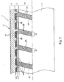
Fig. 3 is a longitudinal sectional view which shows
another embodiment of the flexible insertion tube (flexible
tube for an endoscope according to the present invention).
Hereinbelow, a flexible insertion tube 1' shown in Fig.
3 will be described by focusing on elements that are different
from those described above for the flexible insertion tube 1,
and therefore a description of the same elements will be
omitted.
<Flexible insertion tube 1'>
The flexible insertion tube 1' is the same as the flexible
insertion tube 1 described above except that an outer cover 3'
of the flexible insertion tube 1' is formed into a laminated
structure which includes an inner layer 31, an intermediate
layer 32 and an outer layer 33.
In this embodiment, at least one of the inner layer 31,
the intermediate layer 32 and the outer layer 33 is made of a
material containing polyolefin-based thermoplastic elastomer
and polyolefin in a predetermined compounding ratio.
Hereinbelow, a description will be given for the flexible
insertion tube 1' in which the outer layer 33 is made of a
material containing polyolefin-based thermoplastic elastomer
and polyolefin. That is, the structure (material, shape and
the like) of the outer layer 33 is the same as that of the outer
cover 3 of the embodiment described above.
The average thickness of the outer layer 33 is not limited
to any specific value, but is preferably in the range of about
0.01 to 0.6 mm, more preferably in the range of about 0.03 to
0.5 mm. If the thickness of the outer layer 33 is too small,
there is a case that sufficient chemical resistance and heat
resistance cannot be achieved. On the other hand, if the
thickness of the outer layer 33 it too thick, there is a case
that the flexible insertion tube 1' is difficult to be freely
bent depending on the stiffness of the outer layer 33.
Examples of the constituent material of the inner layer
31 include various resins having flexibility, such as polyvinyl
chloride, polyethylene, polypropylene, ethylene-vinylacetate
copolymer, polyolefin, polyamide, polyester (e.g.,
polyethylene terephthalate (PET), polybutylene terephthalate),
polyurethane, polystyrene resin, fluorine-based resin (e.g.,
polytetrafluoroethylene, ethylene-tetrafluoroethylene
copolymer), and polyimide; and various elastomers such as
polyurethane-based thermoplastic elastomer, polyester-based
thermoplastic elastomer, polyolefin-based thermoplastic
elastomer, polyamide-based thermoplastic elastomer,
polystyrene-based thermoplastic elastomer, fluorine-based
thermoplastic elastomer, silicone rubber, fluorine rubber,
latex rubber; and the like, but are not limited thereto. These
constituent materials can be used singly or in combination of
two or more. Among them, polyurethane-based thermoplastic
elastomer, polyolefin-based thermoplastic elastomer, or
polyester-based thermoplastic elastomer is particularly
preferable. The use of such a material makes it possible to
control the formation of the protruding portions 4 easily.
The average thickness of the inner layer 31 (excluding
those portions corresponding to the protruding portions 4) is
not limited to any specific value, but is preferably in the range
of about 0.03 to 0.8 mm, more preferably in the range of about
0.03 to 0.4 mm.
The intermediate layer 32 is preferably formed as a layer
having better flexibility (resilience) than the outer layer 33.
According to this structure, the intermediate layer 32
functions as a cushioning layer between the inner layer 31 and
the outer layer 33. Further, it is preferred that the
intermediate layer 32 has better flexibility than the inner
layer 31 and has excellent adhesion with the outer layer 33.
The cushioning function of the intermediate layer 32 will
now be described in detail. When the flexible insertion tube
1' is bent, the deformed intermediate layer 32 generates a
strong restoring force because of a high resilience of the
intermediate layer 32. Then, since the intermediate layer 32
is arranged between the outer layer 33 and the inner layer 31
both having relatively high hardness, the restoring force of
the intermediate layer 32 is transmitted efficiently to the
inner layer 31 and the outer layer 33, respectively. As a result,
almost all of the restoring force of the intermediate layer 32
functions as a force for restoring the bent flexible insertion
tube 1'.. Accordingly, by constructing the outer cover 3' to
have such a laminated structure described above, it is possible
to obtain a flexible insertion tube 1' having excellent
resilience.
As for the constituent material of the intermediate layer
32, various resins having flexibility, various elastomers and
the like can be mentioned. Among them, low hardness
polyurethane-based thermoplastic elastomer, polyolefin-based
thermoplastic elastomer, or polyester-based thermoplastic
elastomer is particularly preferable. The use of such a
thermoplastic elastomer, in particular polyolefin-based
thermoplastic elastomer, makes it possible to further improve
adhesion between the outer layer 33 and the intermediate layer
32 and to enhance the resilience of the flexible insertion tube
1' . The use of such a thermoplastic elastomer, in particular
polyolefin-based thermoplastic elastomer, also makes it
possible to further improve adhesion between the outer layer
33 and the intermediate layer 32, thereby enabling to
effectively prevent the deterioration of the flexible insertion
tube 1', such as peeling-off of the outer layer 33 from the
intermediate layer 32, even in a case where the flexible
insertion tube 1' is subjected to repeated bendings. Further,
by forming the intermediate layer 32 using such a constituent
material, it is also possible to improve adhesion between the
intermediate layer 32 and the inner layer 31.
The average thickness of the intermediate layer 32 is not
limited to any specific value, but is preferably in the range
of about 0.02 to 0.8 mm, more preferably in the range of about
0.02 to 0.4 mm.
It should be noted that the laminated structure formed
by laminating the plurality of layers described above may be
provided for the entire length of the flexible insertion tube
1 in the longitudinal direction thereof or for at least a part
of the flexible insertion tube 1 in the longitudinal direction
thereof.
As described above, by constructing the outer cover 3'
from the outer layer 33 having excellent resilience and having
excellent chemical resistance and heat resistance, the
intermediate layer 32 having excellent adhesion with the outer
layer 33 and excellent resilience, and the inner layer 31 having
excellent adhesion with the core member 2, these layers exhibit
their respective functions properly. As a result, the outer
layer 3' can have especially excellent properties because of
a synergistic effect provided by these layers.
This type of flexible insertion tube 1' may be
continuously (uniformly) manufactured by covering the outer
periphery of the core member 2 with the laminated structure
constructed from the inner layer 31, the intermediate layer 32,
and the outer layer 33 by the use of an extrusion molding machine
equipped with a plurality of extrusion openings.
Alternatively, the flexible insertion tube 1' may be
manufactured in the following manner. Specifically, each of
the layers is formed as a hollow tubular body (tube), and then
the core member 2 is inserted into the thus obtained tubular
bodies so that the core member 2, the inner layer 31, the
intermediate layer 32 and the outer layer 33 may be arranged
in this order from the inside to the outside, whereafter a
heating process or the like is carried out to bond these elements
to each other.
The flexible insertion tube 1' having such a structure
and the electronic endoscope 10 equipped with this flexible
insertion tube 1' also have the same effects as those described
above.
In this regard, it should be noted that the outer cover
3' is not limited to one having a structure shown in the drawing.
For example, the outer cover 3' may be constructed from two
layers (e.g., the intermediate layer 32 can be omitted), or the
outer cover 3' may be constructed from four or more layers.
Further, although the outer cover 3' having a structure
in which a layer made of a constituent material containing
polyolefin-based thermoplastic elastomer and polyolefin is
arranged on the outermost peripheral side has been described,
the layer made of such a constituent material containing
polyolefin-based thermoplastic elastomer and polyolefin may be
used as an intermediate layer or an innermost layer.
Furthermore, two or more layers in the outer cover 3' may be
made of such a constituent material containing polyolefin-based
thermoplastic elastomer and polyolefin. In this case, the
compounding ratio of polyolefin-based thermoplastic elastomer
and polyolefin in each of the layers may be the same as to each
other or may be varied among these layers.
Although the flexible tube for an endoscope and the
endoscope according to the present invention have been
described, the present invention is not limited thereto, and
so long as the same functions are achieved, it is possible to
make various changes or additions to each element (portion)
thereof.
In each of the embodiments described above, a flexible
insertion tube has been described as a representative of
flexible tubes for endoscopes, but it goes without saying that
the flexible tube for an endoscope of the present invention can
be applied to flexible connection tubes. Further, although an
electronic endoscope (electronic scope) has been described as
a representative of endoscopes, it goes without saying that the
flexible tube for an endoscope and the endoscope of the present
invention can be applied to optical endoscopes (endoscopes of
fiber scope type).
Further, in each of the embodiments described above, an
endoscope for medical use has been described, but the flexible
tube for an endoscope of the present invention can be applied
to endoscopes for industrial use.
Examples
Next, specific embodiments of the present invention will
be described.
1. Manufacture of flexible tube for an endoscope
(Example 1)
First, a spiral coil having an outer diameter of 9 mm and
an inner diameter of 7 mm was prepared by winding a band-shaped
stainless steel member having a width of 3.2 mm. Then, the
spiral coil was jointed at the one end thereof to nodal rings.
Next, a plurality of bundles each having ten fine wires made
of stainless steel (each of the fine wires had a diameter of
0.08 mm) were prepared, and then these bundles were braided to
obtain a reticular tube. The outer periphery of the spiral coil
with the nodal rings was covered with this reticular tube to
obtain a core member.
Further,-polyolefin-based thermoplastic elastomer and
polyolefin were prepared. The polyolefin-based thermoplastic
elastomer was in the form of a block copolymer which was
comprised of a hard segment constituted from polypropylene and
a soft segment constituted from ethylene-propylene-diene
copolymer, and the polyolefin was homo polypropylene.
Next, these materials are mixed and compounded in a
compounding ratio of 5 parts by weight of polyolefin with
respect to 100 parts by weight of polyolefin-based
thermoplastic elastomer. Then, the outer periphery of the core
member was covered with an outer cover made of the compounded
materials by using the extrusion molding method so that the
thickness of the outer cover might be 0. 4 mm, to obtain a flexible
tube for an endoscope with a length of 1.5 m.
(Examples 2 to 5)
In each of these Examples, a flexible tube for an endoscope
was manufactured in the same manner as in Example 1 except that
the compounding ratio of polyolefin-based thermoplastic
elastomer and polyolefin was changed into each ratio shown in
Table 1.
(Example 6)
A flexible tube for an endoscope was manufactured in the
same manner as in Example 1 except that an outer cover was formed
into a laminated structure including an outer layer, an
intermediate layer and an inner layer, in which the outer layer
was formed of a constituent material containing 5 parts by
weight of polyolefin and 100 parts by weight of polyolefin-based
thermoplastic elastomer.
The laminated structure was manufactured using an
extrusion molding machine equipped with three extrusion
openings. Namely, the outer cover having a laminate structure
was continuously manufactured by extruding the materials of the
inner layer, the intermediate layer and the outer layer
simultaneously so as to cover the core member.
As for the constituent materials of each of the inner and
intermediate layers, polyurethane-based thermoplastic
elastomer (manufactured and sold by DIC Bayer Polymer Ltd. with
the product name of "PANDEX"), and polyolefin-based
thermoplastic elastomer (manufactured and sold by Mitsubishi
Chemical Corporation with the product name of "THERMORUN") were
used, respectively.
Further, the thickness of each of the inner, intermediate
and outer layers were 0.15 mm, 0.1 mm and 0.3 mm, respectively.
(Examples 7 to 10)
In each of these Examples, a flexible tube for an endoscope
was manufactured in the same manner as in Example 6 except that
the compounding ratio of polyolefin-based thermoplastic
elastomer and polyolefin was changed into each ratio shown in
Table 1.
(Comparative Example 1)
A flexible tube for an endoscope was manufactured in the
same manner as in Example 1 except that the constituent material
of the outer cover was changed to polyurethane-based
thermoplastic elastomer (manufactured and sold by DIC Bayer
Polymer Ltd. with the product name of "PANDEX").
(Comparative Example 2)
A flexible tube for an endoscope was manufactured in the
same manner as in Example 1 except that the constituent material
of the outer layer was changed to a material containing no
polyolefin.
(Comparative Examples 3 and 4)
In each of the Comparative Examples, a flexible tube for
an endoscope was manufactured in the same manner as in Example
1 except that the compounding ratio of polyolefin-based
thermoplastic elastomer and polyolefin was changed as shown in
Table 1.
(Comparative Example 5)
A flexible tube for an endoscope was manufactured in the
same manner as in Example 6 except that the constituent material
of the outer layer was changed to polyurethane-based
thermoplastic elastomer (manufactured and sold by DIC Bayer
Polymer Ltd. with the product name of "PANDEX").
(Comparative Example 6)
A flexible tube for an endoscope was manufactured in the
same manner as in Example 6 except that the constituent material
of the outer layer was changed to a material containing no
polyolefin.
(Comparative Examples 7 and 8)
In each of the Comparative Examples, a flexible tube for
an endoscope was manufactured in the same manner as in Example
6 except that the compounding ratio of polyolefin-based
thermoplastic elastomer and polyolefin was changed as shown in
Table 1.
The constituent material and the average thickness of the
outer cover of each of Examples and Comparative Examples are
shown in Table 1 (it should be noted that, in the case of each
of Examples 6 to 10, the constituent material and the average
thickness of the outer layer thereof are shown).
Further, it should be noted that in the Table 1
polyolefin-based thermoplastic elastomer, polyolefin,
polyurethane-based thermoplastic elastomer are abbreviated as
"TPO", "PO" and "TPU", respectively.
| | Constituent material of outer cover | Average thickness (mm) |
| Example 1 | TPO: 100 parts by weight PO: 5 parts by weight | 0.4 |
| Example 2 | TPO: 100 parts by weight PO: 10 parts by weight | 0.4 |
| Example 3 | TPO: 100 parts by weight PO: 30 parts by weight | 0.4 |
| Example 4 | TPO: 100 parts by weight PO: 50 parts by weight | 0.4 |
| Example 5 | TPO: 100 parts by weight PO: 70 parts by weight | 0.4 |
| Example 6 | TPO: 100 parts by weight PO: 5 parts by weight | 0.3 |
| Example 7 | TPO: 100 parts by weight PO: 10 parts by weight | 0.3 |
| Example 8 | TPO: 100 parts by weight PO: 30 parts by weight | 0.3 |
| Example 9 | TPO: 100 parts by weight PO: 50 parts by weight | 0.3 |
| Example 10 | TPO: 100 parts by weight PO: 70 parts by weight | 0.3 |
| Comp. Ex. 1 | TPU | 0.4 |
| Comp. Ex. 2 | TPO | 0.4 |
| Comp. Ex. 3 | TPO: 100 parts by weight PO: 2 parts by weight | 0.4 |
| Comp. Ex. 4 | TPO: 100 parts by weight PO: 90 parts by weight | 0.4 |
| Comp. Ex. 5 | TPU | 0.3 |
| Comp. Ex. 6 | TPO | 0.3 |
| Comp. Ex. 7 | TPO: 100 parts by weight PO: 2 parts by weight | 0.3 |
| Comp. Ex. 8 | TPO: 100 parts by weight PO: 90 parts by weight | 0.3 |
Chemical resistance test was carried out on the flexible
tube for an endoscope manufactured in each of Examples and
Comparative Examples in the following manner.
In this chemical resistance test, each of the flexible
tubes for endoscopes was subjected to a cleaning and
disinfection operation by the use of a heating-type cleaner
(manufactured and sold by BHT Corp. with the product name of
"SME 2000").
This cleaning and disinfection operation was carried out
through four processes, i.e., a cleaning process using a
cleaning solution (nonionic surfactant)(about 10 minutes), a
disinfection process using a disinfectant solution (about 0.24
wt% aqueous glutaraldehyde solution) (about 10 minutes), a
washing process using hot water at about 60°C (about 10 minutes),
and a drying process with hot air (about 5 minutes).
After this cleaning and disinfection operation was
repeated 2,000 times, the appearance of the flexible tube for
an endoscope was observed, and was then evaluated according to
the following four criteria.
2.2 Heat resistance test
Heat resistance test was carried out on the flexible tube
for an endoscope manufactured in each of Examples and
Comparative Examples in the following manner.
Three flexible tubes for endoscopes were prepared for
each of Examples and Comparative Examples. Each of the flexible
tubes for endoscopes was subjected to autoclave sterilization
for 15 minutes at a temperature of 135°C and under a pressure
of 2.2 atmospheres, and was then rapidly cooled in ice water.
This series of operations was repeated 20 times.
After the series of operations was repeated 20 times, the
degree of deterioration of each of the flexible tubes for
endoscopes, especially the degree of loss (lowering) of
flexibility was examined, and was then evaluated according to
the following four criteria.
2.3 Resilience test
Resilience test was carried out on the flexible tube for
an endoscope manufactured in each of Examples and Comparative
Examples in the following manner.
In this resilience test, ten flexible tubes for
endoscopes were prepared for each of Examples and Comparative
Examples, and then these ten flexible tubes for endoscopes were
tied in a bundle to examine whether or not this bundle could
be bent.
After such bending operation was carried out, the
resilience of each of the flexible tubes for endoscopes was
evaluated according to the following four criteria.
The results of these evaluations are shown in Table 2.
| | Chemical Resistance | Heat resistance | Resilience |
| Example 1 | A | A | C |
| Example 2 | A | A | B |
| Example 3 | A | A | A |
| Example 4 | A | A | B |
| Example 5 | A | A | C |
| Example 6 | A | A | B |
| Example 7 | A | A | A |
| Example 8 | A | A | A |
| Example 9 | A | A | A |
| Example 10 | A | A | B |
| Comp. Ex. 1 | D | D | A |
| Comp. Ex. 2 | A | A | D |
| Comp. Ex. 3 | A | A | D |
| Comp. Ex. 4 | A | A | D |
| Comp. Ex. 5 | D | D | A |
| Comp. Ex. 6 | A | A | D |
| Comp. Ex. 7 | A | A | D |
| Comp. Ex. 8 | A | A | D |
As is apparent from Table 2, all of the flexible tubes
for endoscopes of the present invention had excellent chemical
resistance and heat resistance with retaining adequate
resilience.
On the other hand, the flexible tubes for endoscopes of
Comparative Examples were inferior in performance to those of
Examples.
Effects of the Invention
As has been described above, according to the present
invention, it is possible to obtain a flexible tube for an
endoscope having excellent chemical resistance and heat
resistance with retaining resilience.
In particular, in a case where the outer cover is formed
into a laminated structure constructed from a plurality of
layers, these layers exhibit their respective functions so that
the flexible tube for an endoscope can have especially excellent
properties due to a synergistic effect among the layers.
Finally, it is to be understood that many changes and
additions may be made to the embodiments described above without
departing from the scope and spirit of the invention as defined
in the following claims.
Further, it is also to be understood that the present
disclosure relates to subject matter contained in Japanese
Patent Application No: 2003-188088 (filed on June 30, 2003)
which is expressly incorporated herein by reference in its
entirety.