EP1493316B1 - Vorrichtung zur Messung der Pflanzenbestandsdichte - Google Patents
Vorrichtung zur Messung der Pflanzenbestandsdichte Download PDFInfo
- Publication number
- EP1493316B1 EP1493316B1 EP04014941A EP04014941A EP1493316B1 EP 1493316 B1 EP1493316 B1 EP 1493316B1 EP 04014941 A EP04014941 A EP 04014941A EP 04014941 A EP04014941 A EP 04014941A EP 1493316 B1 EP1493316 B1 EP 1493316B1
- Authority
- EP
- European Patent Office
- Prior art keywords
- sensor
- vegetation
- density
- signals
- determined
- Prior art date
- Legal status (The legal status is an assumption and is not a legal conclusion. Google has not performed a legal analysis and makes no representation as to the accuracy of the status listed.)
- Not-in-force
Links
Images


Classifications
-
- A—HUMAN NECESSITIES
- A01—AGRICULTURE; FORESTRY; ANIMAL HUSBANDRY; HUNTING; TRAPPING; FISHING
- A01B—SOIL WORKING IN AGRICULTURE OR FORESTRY; PARTS, DETAILS, OR ACCESSORIES OF AGRICULTURAL MACHINES OR IMPLEMENTS, IN GENERAL
- A01B79/00—Methods for working soil
- A01B79/005—Precision agriculture
-
- A—HUMAN NECESSITIES
- A01—AGRICULTURE; FORESTRY; ANIMAL HUSBANDRY; HUNTING; TRAPPING; FISHING
- A01C—PLANTING; SOWING; FERTILISING
- A01C21/00—Methods of fertilising, sowing or planting
- A01C21/007—Determining fertilization requirements
Definitions
- the invention relates to a device for measuring the plant density according to the preamble of claim 1.
- DE 195 28 663 A1 is a method for setting a mobile machine, including a fertilizer spreader, so a distributor described.
- an advance scan is carried out by means of a suitable sensor in order to determine, among other things, the stock level or the expected yield.
- the invention has the object to provide an inexpensive sensor system for green mass determination.
- the characterizing features of claim 1. As a result of these measures can be determined in a simple manner with a low-cost sensor or more inexpensive sensors, the green mass.
- the green mass is a measure of the population density. Based on the determined values, the required amount of fertilizer can be determined. On the basis of the determined values, the distribution machine can then be adjusted accordingly in order to enable optimum fertilizer application in accordance with the actually determined green mass.
- An optoelectronic distance sensor is understood to mean an optoelectronic sensor or optoelectronic sensor system for distance measurement, such as this u.a. Triangulation sensors, laser sensors for distance measurement, runtime sensors are.
- the data collected by the sensors can be used in addition to the determination of site-specific fertilizer demand and its distribution in other areas. For example, it is possible to determine the track depth, the correlation to the yield, obstacles can be detected and, for example, trial areas can be evaluated.
- a simple determination of crop density i.
- the green mass is achieved by means of an evaluation program in a simple manner that in the evaluation program, a statistical relationship between number of "ground” signals and "plant” signals is stored and based on this stored ratio by comparing with the currently determined ratios, the actual population density determined online and based on the values determined online by means of a stored program, the distributor is adjustable accordingly.
- the site-specific fertilizer requirement is then determined from the determined stocking density by means of the stored program, and the distribution machine is set accordingly.
- the optoelectronic distance sensors can be designed as triangulation sensor, travel time sensors, scanner, laser sensor. One or more sensors may be provided.
- the sensor emits light (for example LED or laser light, preferably in the IR range, but there are also sensors with white light).
- the light can be emitted continuously or pulsed.
- the reflected light is measured. This can be done using the triangulation principle (for continuous light) or over the runtime (for pulsed light). The evaluation of the triangulation or transit time measurement gives the distance.
- a scanner can also be used as a sensor. If you extend the punctiform detection of an optoelectronic distance sensor to many measurement points in a row, you get a distance scanner for complete profile measurement (similar to an optical scanner with a CCD line). When installed vertically, this corresponds in function to a large number of triangulation sensors. It a plurality of optoelectronic distance sensors can be designed in the form of a line scanner.
- 3 D cameras can be used, which provide areal distance information. If you use a single laser sensor and change its position, you can also measure a profile.
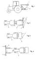
- the sensor 1 of the device for measuring the crop density is arranged laterally on a distributor 2.
- This distributor 2 is carried by a tractor 3 over the field.
- the sensor 1 of the device for measuring the crop density is arranged on a linkage 4 behind a distributor 2, which is carried by an agricultural tractor 3.
- a total of three sensors 1 are provided.
- the sensors 1 of the plant density measuring apparatus are disposed at the rear side ends of a distribution machine 2.
- This distributor 2 is carried by a tractor 3 over the field.
- Fig. 4 are the sensors 1 of the device for measuring the plant density on a rod 5, which is located on the front of the tractor 2, which carries a distributor 2 is arranged.
- the sensor 1 for measuring the crop density is designed as an optoelectronic distance sensor, for example as a triangulation sensor. It uses sensors that emit continuous or pulsed light (LED, laser, white light) and measure the reflected light. Measuring principles are the triangulation (two-beam or three-beam principle) or the transit time measurement. The principle of operation of a two-beam triangulation sensor of this sensor is exemplified in FIG Fig. 5 shown.
- the triangulation sensor 1 has a light emitting laser diode 6 designed as a transmitter. This laser diode 6 sends the light 7 through a lens 8 of the optics in the direction of the bottom 9 and the plants 10.
- the reflected light 11 is passed through the receiving lens 12 of the optics and arrives at the designed as a receiver position sensor 13.
- About the lens 8 is formed as a lens Point of light projected onto the measuring objective, ground, plant and diffusely reflected from there. This point is imaged on the position sensor 13 (receiver) via the objective 12.
- the position sensor 13 supplies a position-dependent analog output voltage which is proportional to the measuring path (distance sensor measuring object).
- the Fig. 6 shows the evaluation principle of the value received from the various sensors 1 and the transmitted measured values to an electronic computer. Depending on the number of sensors, the measured values in the controller 14 are evaluated and calculated. In this controller 14, the stand height is determined from the height measurement during the crossing. Erroneous data can be eliminated via a software filtering. Due to the pre - formed measuring principle of the optoelectronic distance sensors of the triangulation sensor, the in Fig. 8 mapped statistical distribution 15 of the sensor signals achieved.
- Fig. 7 the determination of the stand height B is shown, wherein the distance a is the plant height b plus the lane depth c of the tractor.
- the measurement is carried out to determine the green mass of the plant population by means of one or more trained as a triangulation sensor 1 optoelectronic distance sensors.
- These trained as Triangulationssenoren distance sensors which have a transmitter 6 and receiver 13, provide appropriate signals to an on-board computer.
- the stand height of the plant population can be determined.
- the plant density can be determined by means of an evaluation program stored in the on-board computer in a storage medium.
- the evaluation program stores a statistical ratio between the number of soil signals and plant signals. On the basis of this stored ratio, the actual stock density, i. E. the green mass is determined online. Based on the values determined online, the distributor can be set accordingly by means of a stored program. Thus, the location-specific fertilizer requirements can be determined from the determined stock density using the stored program. The distribution machine will be adjusted accordingly, so that the determined fertilizer requirement is applied by the distributor.
Description
- Die Erfindung betrifft eine Vorrichtung zur Messung der Pflanzenbestandsdichte gemäß des Oberbegriffes des Patentanspruches 1.
- In der
DE 195 28 663 A1 wird ein Verfahren zur Einstellung einer mobilen Arbeitsmaschine, u.a. auch eines Düngerstreuers, also einer Verteilmaschine beschrieben. Hierbei wird mittels eines geeigneten Sensors eine Vorfeldabtastung durchgeführt, um u.a. die Bestandshöhe oder den zu erwartenden Ertrag zu ermitteln. - Eine ähnliche Vorrichtung ist auch aus der
WO 03/010535 - Der Erfindung liegt die Aufgabe zugrunde, ein preiswertes Sensorsystem zur Grünmassenbestimmung vorzuschlagen.
- Diese Aufgabe wird erfindungsgemäß durch die kennzeichnenden Merkmale des Patentanspruches 1 gelöst. Infolge dieser Maßnahmen kann in einfacher Weise mit einem preiswerten Sensor oder mehrerer preiswerter Sensoren die Grünmasse bestimmt werden. Die Grünmasse ist ein Maß für die Bestandsdichte. Anhand der ermittelten Werte lässt sich die erforderliche Düngemittelmenge ermitteln. Aufgrund der ermittelten Werte kann dann die Verteilmaschine entsprechend eingestellt werden, um eine optimale Düngemittelausbringung entsprechend der tatsächlich ermittelten Grünmasse zu ermöglichen.
- Besonders gute Werte lassen sich ermitteln, wenn in der Auswertung Elemente zur Filterung der Daten und der Lichtsignale vorgenommen werden. Viele der zum Einsatz kommenden Sensortypen haben einen Fehlerausgang, so dass man die entsprechenden Signale softwaremäßig über eine Filterung ausblenden kann. Eine derartige Filterung sowie gegebenenfalls andere softwaremäßige Reduktionen der Messdaten sind als Zwischenschritt der Datenauswertung, z.B. als "Datenfilterung" in vielen Fällen wichtig.
- Unter einem optoelektronischen Abstandssensor wird ein optoelektronischer Sensor oder optoelektronisches Sensorsystem zur Abstandsmessung verstanden, wie dieses u.a. Triangulationssensoren, Lasersensoren zur Abstandsmessung, Laufzeitsensoren sind.
- Die ermittelten Daten, die von den Sensoren ermittelt werden, lassen sich neben der Ermittlung des standortspezifischen Düngerbedarfs und dessen Verteilung auch auf andere Gebiete einsetzen. Es kann beispielsweise die Spurtiefe ermittelt werden, die Korrelation zum Ertrag, Hindernisse können erkannt werden und es können beispielsweise Versuchsflächen ausgewertet werden.
- Eine einfache Ermittlung der Pflanzenbestandsdichte, d.h. der Grünmasse wird mittels eines Auswerteprogramms in einfacher Weise dadurch erreicht, dass in dem Auswerteprogramm ein statistisches Verhältnis zwischen Anzahl "Boden"-Signale und "Pflanzen"-Signale abgelegt ist und anhand dieses hinterlegten Verhältnisses durch den Abgleich mit den aktuell ermittelten Verhältnissen die tatsächliche Bestandsdichte online ermittelt und aufgrund der online ermittelten Werte mittels eines hinterlegten Programms die Verteilmaschine entsprechend einstellbar ist.
- Hierbei wird dann aus der ermittelten Bestandsdichte mittels des hinterlegten Programms der standortspezifische Düngerbedarf ermittelt und die Verteilmaschine entsprechend eingestellt.
- Wie bereits vor erwähnt, können die optoelektronischen Abstandssensoren als Triangulationssensor, Laufzeitsensoren, Scanner, Lasersensor ausgebildet sein. Es können ein oder mehrere Sensoren vorgesehen sein.
- Das verallgemeinerte Prinzip lässt sich folgender Maßen darstellen:
- Der Sensor sendet Licht aus (z.B. LED- oder Laserlicht, bevorzugt im IR-Bereich; es gibt aber auch Sensoren mit Weißlicht). Das Licht kann kontinuierlich oder gepulst ausgesendet werden.
- Das reflektierte Licht wird gemessen. Dies kann über das Triangulationsprinzip (für kontinuierliches Licht) oder über die Laufzeit (für gepulstes Licht) geschehen. Die Auswertung der Triangulations- oder Laufzeitmessung ergibt den Abstand.
- Bei den Triangulationssensoren gibt es neben dem klassischen Zweitstrahlprinzip auch ein Dreistrahl-Prinzip mit höherer Genauigkeit. Hier wird ein zweites positionsempfindliches Element symmetrisch zum gesendeten Lichtstrahl eingebaut. Solche Sensoren (z.B. von der Firma Wenglor) sind extrem unempfindlich gegenüber Störlicht oder Änderungen der Oberflächenbeschaffenheit.
- Des weiteren kann auch ein Scanner als Sensor eingesetzt werden. Erweitert man die punktförmige Erfassung eines optoelektronischen Abstandssensors auf viele Messpunkte in einer Zeile, so erhält man einen Abstands-Scanner zur kompletten Profilmessung (ähnlich einem optischen Scanner mit einer CCD-Zeile). Beim senkrechten Einbau entspricht dies in der Funktion einer Vielzahl von Triangulationssensoren. Es können mehrere optoelektronische Abstandssensoren in Form eines Zeilenscanners ausgebildet sein.
- Des weiteren sind auch 3 D-Kameras einsetzbar, die eine flächenhafte Abstandsinformation liefern. Verwendet man einen einzelnen Lasersensor und verändert dessen Position, so kann man ebenfalls ein Profil messen.
- Weitere Einzelheiten der Erfindung sind der Beispielsbeschreibung und den Zeichnungen zu entnehmen. Hierbei zeigen
- Fig. 1
- die Anordnung des Sensors an einer Verteilmaschine in Seitenansicht und in Prinzipdarstellung,
- Fig. 2
- eine weitere Anordnung der Sensoren bezüglich einer Verteilmaschine in der Draufsicht,
- Fig. 3
- eine weitere Anordnung der Sensoren bezüglich einer Verteilmaschine in der Draufsicht und in Prinzipdarstellung,
- Fig. 4
- eine weitere Darstellung der Anordnung der Sensoren bezüglich einer Verteilmaschine in Prinzipdarstellung und in der Draufsicht,
- Fig. 5
- Darstellung eines Messprinzips für einen als Zweistrahl-Triangulationssensor ausgebildete optoelektronischen Abstandssensor,
- Fig. 6
- die Auswertung der Daten in einem Funktionsablaufdiagramm,
- Fig. 7
- das Messprinzip anhand eines Getreidebestandes und
- Fig. 8
- die Darstellung der Signale in einem Diagramm.
- Bei der Ausführung nach
Fig. 1 ist der Sensor 1 der Vorrichtung zur Messung der Pflanzenbestandsdichte seitlich an einer Verteilmaschine 2 angeordnet. Diese Verteilmaschine 2 wird von einem Schlepper 3 über den Acker getragen. - Gemäß
Fig. 2 ist der Sensor 1 der Vorrichtung zur Messung der Pflanzenbestandsdichte an einem Gestänge 4 hinter einer Verteilmaschine 2, die von einem Ackerschlepper 3 getragen wird angeordnet. Bei dieser Vorrichtung sind insgesamt drei Sensoren 1 vorgesehen. - Gemäß
Fig. 3 sind die Sensoren 1 der Vorrichtung zur Messung der Pflanzenbestandsdichte an den hinteren seitlichen Enden einer Verteilmaschine 2 angeordnet. Diese Verteilmaschine 2 wird von einem Schlepper 3 über den Acker getragen. - Gemäß
Fig. 4 sind die Sensoren 1 der Vorrichtung zur Messung der Pflanzenbestandsdichte an einem Gestänge 5, welches sich auf der Vorderseite des Ackerschleppers 2 befindet, welches eine Verteilmaschine 2 trägt angeordnet. - Der Sensor 1 zur Messung der Pflanzenbestandsdichte ist als optoelektronischer Abstandssensor, beispielsweise als Triangulationssensor ausgebildet. Dabei werden Sensoren verwendet, die kontinuierliches oder gepulstes Licht (LED, Laser, Weißlicht) aussenden und das reflektierte Licht messen. Messprinzipien sind die Triangulation (Zweistrahl- oder Dreistrahlprinzip) oder die Laufzeitmessung. Das Funktionsprinzip eines Zweistrahl-Triangulationssensorsdieses Sensors ist als Beispiel in
Fig. 5 dargestellt. Der Triangulationssensor 1 weist eine als Sender ausgebildete lichtaussendende Laserdiode 6 auf. Diese Laserdiode 6 sendet das Licht 7 durch eine Linse 8 der Optik in Richtung des Bodens 9 und der Pflanzen 10. Das zurückgeworfene Licht 11 wird durch die Empfangslinse 12 der Optik geleitet und gelangt auf den als Empfänger ausgebildeten Positionssensor 13. Über die als Linse 8 ausgebildete Objektiv wird ein Lichtpunkt auf das Messobjektiv, Boden, Pflanze projeziert und wird von dort diffus reflektiert. Dieser Punkt wird über das Objektiv 12 auf den Positionssensor 13 (Empfänger) abgebildet. Der Positionssensor 13 liefert eine positionsabhängige analoge Ausgangsspannung, die dem Messweg (Abstandssensor Messobjekt) proportional ist. - Die
Fig. 6 zeigt das Auswerteprinzip der von dem verschiedenen Sensoren 1 empfangenen Wert und der übermittelten Messwerte an einen elektronischen Rechner. Je nach Anzahl der Sensoren werden die Messwerte in dem Controller 14 ausgewertet und errechnet. In diesem Controller 14 wird aus der Höhenmessung während der Überfahrt die Bestandeshöhe ermittelt. Fehlerhafte Daten können über eine softwaremäßige Filterung eliminiert werden. Aufgrund ders vorgeschilderten Messprinzipiens der optoelektronischen Abstandssensorendes Triangulationssensors wird die inFig. 8 abgebildete statistische Verteilung 15 der Sensorsignale erreicht. - In
Fig. 7 ist die Ermittlung der Bestandeshöhe B dargestellt, wobei der Abstand a die Pflanzenhöhe b plus der Fahrspurtiefe c des Schleppers ist. Neben der absoluten Bestandeshöhe b, b' ergibt sich aufgrund der Statistik das Verhältnis zwischen der Anzahl der Bodentreffer und der Bestandestreffer, aus denen sich die Bestandeshöhe entsprechendFig. 6 ermitteln lässt. Aus der Korrelation zwischen Bestandeshöhe und Dichte des Bestandes werden Rückschlüsse auf die Düngerversorgung der Pflanzen gezogen. - Insbesondere wie sich aus
Fig. 6 ergibt, erfolgt die Messung zur Bestimmung der Grünmasse des Pflanzenbestandes mittels eines oder mehrerer als Triangulationssensor 1 ausgebildeter optoelektronischer Abstandssensoren. Diese als Triangulationssenoren ausgebildeten Abstandssensoren, die einen Sender 6 und Empfänger 13 aufweisen, liefern entsprechende Signale an einen Bordcomputer. Mittels des Sensors 1 lässt sich die Bestandeshöhe des Pflanzenbestands ermitteln. Aus den Signalen ist mittels eines im Bordcomputer in einem Speichermedium abgelegten Auswerteprogramms die Pflanzenbestandsdichte ermittelbar. - In dem Auswerteprogramm ist ein statistisches Verhältnis zwischen Anzahl Bodensignalen und Pflanzensignalen abgelegt. Anhand dieses hinterlegten Verhältnisses wird durch den Abgleich mit den aktuell ermittelten Verhältnissen die tatsächliche Bestandesdichte, d.h. die Grünmasse online ermittelt. Aufgrund der Online ermittelten Werte ist mittels eines hinterlegten Programms die Verteilmaschine entsprechend einstellbar. Somit ist aus der ermittelten Bestandsdichte mittels des hinterlegten Programms der standortspezifische Düngerbedarf ermittelbar. Die Verteilmaschine wird entsprechend einzustellen, damit der ermittelte Düngemittelbedarf durch die Verteilmaschine ausgebracht wird.
Claims (8)
- Vorrichtung zur Messung der Pflanzenbestandsdichte, insbesondere der Grünmasse des Pflanzenbestandes einer landwirtschaftlichen Bestandsfläche zur Steuerung und/oder Regelung einer landwirtschaftlichen Verteilmaschine (2), wobei die Vorrichtung mindestens einen Signale an einen Bordcomputer liefernden Sensor (1) mit einem Sender (6) und einem Empfänger (13) aufweist, wobei der Sensor (1) als optoelektronischer Abstandssensor ausgebildet ist, dadurch gekennzeichnet, dass mittels des Sensors (1) die absolute Bestandshöhe des Pflanzenbestandes (b,b') ermittelbar ist, dass aus den Signalen mittels eines im Bordcomputer in einem Speichermedium abgelegten Auswerteprogramms die Pflanzenbestandsdichte ermittelbar ist, und dass aufgrund eines Fehlergangs am Sensor (1) softwaremäßig über eine Filterung fehlerhafte Signale ausblendbar sind.
- Vorrichtung nach Anspruch 1, dadurch gekennzeichnet, dass in dem Auswerteprogramm ein statistisches Verhältnis zwischen Anzahl "Boden"-Signale und "Pflanzen"-Signale abgelegt ist und anhand dieses hinterlegten Verhältnisses durch den Abgleich mit den aktuell ermittelten Verhältnissen die tatsächliche Bestandsdichte online ermittelt und aufgrund der online ermittelten Werte mittels eines hinterlegten Programms die Verteilmaschine (2) entsprechend einstellbar ist.
- Vorrichtung nach Anspruch 2, dadurch gekennzeichnet, dass aus der ermittelten Bestandsdichte mittels des hinterlegten Programms der standortspezifische Düngerbedarf ermittelbar ist, und dass die Verteilmaschine (2) entsprechend einstellbar ist.
- Vorrichtung nach Anspruch 1, dadurch gekennzeichnet, dass der Sensor (1) als Triangulationssensor ausgebildet ist.
- Vorrichtung nach Anspruch 1, dadurch gekennzeichnet, dass der Sensor (1) als Laufzeitsensor ausgebildet ist.
- Vorrichtung nach Anspruch 1, dadurch gekennzeichnet, dass der Sensor (1) als Scanner ausgebildet ist.
- Vorrichtung nach Anspruch 1, dadurch gekennzeichnet, dass der Sensor (1) als Lasersensor ausgebildet ist.
- Vorrichtung nach Anspruch 1, dadurch gekennzeichnet, dass mehrere Sensoren (1) vorgesehen sind.
Priority Applications (1)
| Application Number | Priority Date | Filing Date | Title |
|---|---|---|---|
| PL04014941T PL1493316T3 (pl) | 2003-07-01 | 2004-06-25 | Urządzenie do pomiaru gęstości inwentarza roślinnego |
Applications Claiming Priority (4)
| Application Number | Priority Date | Filing Date | Title |
|---|---|---|---|
| DE2003129472 DE10329472A1 (de) | 2003-07-01 | 2003-07-01 | Vorrichtung zur Messung der Pflanzenbestandsdichte |
| DE10329472 | 2003-07-01 | ||
| DE2003149324 DE10349324A1 (de) | 2003-10-23 | 2003-10-23 | Vorrichtung zur Messung der Pflanzenbestandsdichte |
| DE10349324 | 2003-10-23 |
Publications (2)
| Publication Number | Publication Date |
|---|---|
| EP1493316A1 EP1493316A1 (de) | 2005-01-05 |
| EP1493316B1 true EP1493316B1 (de) | 2008-02-13 |
Family
ID=33435981
Family Applications (1)
| Application Number | Title | Priority Date | Filing Date |
|---|---|---|---|
| EP04014941A Not-in-force EP1493316B1 (de) | 2003-07-01 | 2004-06-25 | Vorrichtung zur Messung der Pflanzenbestandsdichte |
Country Status (5)
| Country | Link |
|---|---|
| EP (1) | EP1493316B1 (de) |
| AT (1) | ATE385671T1 (de) |
| DE (1) | DE502004006160D1 (de) |
| DK (1) | DK1493316T3 (de) |
| PL (1) | PL1493316T3 (de) |
Families Citing this family (5)
| Publication number | Priority date | Publication date | Assignee | Title |
|---|---|---|---|---|
| WO2006132549A1 (en) | 2005-06-08 | 2006-12-14 | Massey University | Improvements in or relating to pasture management |
| DE102014106775A1 (de) * | 2014-05-14 | 2015-11-19 | Amazonen-Werke H. Dreyer Gmbh & Co. Kg | Landwirtschaftliche Arbeitsmaschine |
| EP3343170A1 (de) | 2016-12-27 | 2018-07-04 | Yara International ASA | Vorrichtung und verfahren zur bestimmung der höhe eines landwirtschaftlichen produkts |
| US11944087B2 (en) | 2020-12-21 | 2024-04-02 | Deere & Company | Agricultural sprayer with real-time, on-machine target sensor |
| US11832609B2 (en) | 2020-12-21 | 2023-12-05 | Deere & Company | Agricultural sprayer with real-time, on-machine target sensor |
Family Cites Families (6)
| Publication number | Priority date | Publication date | Assignee | Title |
|---|---|---|---|---|
| US5585626A (en) * | 1992-07-28 | 1996-12-17 | Patchen, Inc. | Apparatus and method for determining a distance to an object in a field for the controlled release of chemicals on plants, weeds, trees or soil and/or guidance of farm vehicles |
| DE19528663A1 (de) | 1995-08-04 | 1997-02-06 | Univ Hohenheim | Verfahren zur Einstellung einer mobilen Arbeitsmaschine |
| DE19723770A1 (de) * | 1997-06-06 | 1998-12-10 | Hydro Agri Deutschland Gmbh | Pflanzenzustandsmeßvorrichtung |
| US6444975B1 (en) * | 1998-09-03 | 2002-09-03 | Norsk Hydro Asa | Method and device for fertilizing specific partial areas of plants |
| US6601341B2 (en) * | 2001-07-24 | 2003-08-05 | The Board Of Regents For Oklahoma State University | Process for in-season fertilizer nitrogen application based on predicted yield potential |
| WO2003010535A1 (en) * | 2001-07-25 | 2003-02-06 | Ministeriet For Fødevarer, Landbrug Og Fiskeri | Improved real time method for controlling applications of fertilizers and other yield improving agents to crops |
-
2004
- 2004-06-25 DK DK04014941T patent/DK1493316T3/da active
- 2004-06-25 EP EP04014941A patent/EP1493316B1/de not_active Not-in-force
- 2004-06-25 DE DE502004006160T patent/DE502004006160D1/de active Active
- 2004-06-25 PL PL04014941T patent/PL1493316T3/pl unknown
- 2004-06-25 AT AT04014941T patent/ATE385671T1/de not_active IP Right Cessation
Also Published As
| Publication number | Publication date |
|---|---|
| DK1493316T3 (da) | 2008-06-16 |
| EP1493316A1 (de) | 2005-01-05 |
| ATE385671T1 (de) | 2008-03-15 |
| DE502004006160D1 (de) | 2008-03-27 |
| PL1493316T3 (pl) | 2008-04-30 |
Similar Documents
| Publication | Publication Date | Title |
|---|---|---|
| EP2944171B1 (de) | Landwirtschaftliche arbeitsmaschine | |
| DE102015111889B4 (de) | Verfahren zur Prüfung einer landwirtschaftlichen Sprüheinrichtung | |
| DE4301228C1 (de) | Verfahren zur Bestimmung der Sichtweite | |
| DE102008009753B3 (de) | Verfahren zum Bestimmen der Biomasse und Morphologie von Pflanzenbeständen mittels Ultraschall | |
| WO2008064800A1 (de) | Verfahren und anordnung zur steuerung eines fahrzeuges | |
| EP0743001B1 (de) | Vorrichtung und Verfahren zum Besprühen von Raumkulturen | |
| DE102005013365A1 (de) | Messvorrichtung und Verfahren zur Bodenoberflächenanalyse für Rasenpflege-Roboter | |
| EP3738420B1 (de) | Verfahren für den betrieb einer selbstfahrenden landwirtschaftlichen arbeitsmaschine | |
| DE4004247A1 (de) | Servo-geregeltes bearbeitungs-grundgeraet mit elektronischer pflanzenabtastung | |
| DE19858168B4 (de) | Vorrichtung und Verfahren zur berührungslosen Ermittlung des Pflanzenbewuchses eines Feldabschnittes | |
| DE102020121100A1 (de) | System und Verfahren für eine landwirtschaftliche Verteilmaschine und landwirtschaftliche Verteilmaschine | |
| EP1493316B1 (de) | Vorrichtung zur Messung der Pflanzenbestandsdichte | |
| DE19544112A1 (de) | Verfahren zur Generierung digitaler Geländemodelle | |
| DE10349324A1 (de) | Vorrichtung zur Messung der Pflanzenbestandsdichte | |
| WO2020164834A1 (de) | Trajektoriebestimmung für landmaschinen unter verwendung von rasterkarten | |
| DE102019114866A1 (de) | Steuersystem und Verfahren zum Betreiben einer landwirtschaftlichen Arbeitsmaschine sowie landwirtschaftliche Arbeitsmaschine | |
| DE102018128378A1 (de) | Verfahren zum Erfassen des Abstands eines Gestänges zu einer landwirtschaftlichen Nutzfläche und/oder deren Pflanzenbestand | |
| DE10346541A1 (de) | Einrichtung und Verfahren zum Messen der Ausbildung von Pflanzenbeständen | |
| DE102018104205A1 (de) | Verfahren zur Ermittlung der Bestandsdichte eines Feldbestands | |
| DE102004004133A1 (de) | Verfahren und Vorrichtung zum optischen Zählen kleiner Körperchen | |
| DE10329472A1 (de) | Vorrichtung zur Messung der Pflanzenbestandsdichte | |
| DE102008005191A1 (de) | Sensoranordnung | |
| DE102018204301B4 (de) | Verfahren zum Ermitteln einer Bestandhöhe von Feldpflanzen | |
| EP3699639A1 (de) | Spritzgestänge für ein landwirtschaftliches spritzgerät | |
| DE19858157C2 (de) | Vorrichtung und Verfahren zur berührungslosen Ermittlung des Pflanzenbewuchses eines Feldabschnittes |
Legal Events
| Date | Code | Title | Description |
|---|---|---|---|
| PUAI | Public reference made under article 153(3) epc to a published international application that has entered the european phase |
Free format text: ORIGINAL CODE: 0009012 |
|
| AK | Designated contracting states |
Kind code of ref document: A1 Designated state(s): AT BE BG CH CY CZ DE DK EE ES FI FR GB GR HU IE IT LI LU MC NL PL PT RO SE SI SK TR |
|
| AX | Request for extension of the european patent |
Extension state: AL HR LT LV MK |
|
| 17P | Request for examination filed |
Effective date: 20050506 |
|
| AKX | Designation fees paid |
Designated state(s): AT BE BG CH CY CZ DE DK EE ES FI FR GB GR HU IE IT LI LU MC NL PL PT RO SE SI SK TR |
|
| GRAP | Despatch of communication of intention to grant a patent |
Free format text: ORIGINAL CODE: EPIDOSNIGR1 |
|
| GRAS | Grant fee paid |
Free format text: ORIGINAL CODE: EPIDOSNIGR3 |
|
| GRAA | (expected) grant |
Free format text: ORIGINAL CODE: 0009210 |
|
| AK | Designated contracting states |
Kind code of ref document: B1 Designated state(s): AT BE BG CH CY CZ DE DK EE ES FI FR GB GR HU IE IT LI LU MC NL PL PT RO SE SI SK TR |
|
| REG | Reference to a national code |
Ref country code: GB Ref legal event code: FG4D Free format text: NOT ENGLISH |
|
| REG | Reference to a national code |
Ref country code: CH Ref legal event code: EP |
|
| REG | Reference to a national code |
Ref country code: IE Ref legal event code: FG4D Free format text: LANGUAGE OF EP DOCUMENT: GERMAN |
|
| REF | Corresponds to: |
Ref document number: 502004006160 Country of ref document: DE Date of ref document: 20080327 Kind code of ref document: P |
|
| REG | Reference to a national code |
Ref country code: PL Ref legal event code: T3 |
|
| REG | Reference to a national code |
Ref country code: DK Ref legal event code: T3 |
|
| PG25 | Lapsed in a contracting state [announced via postgrant information from national office to epo] |
Ref country code: ES Free format text: LAPSE BECAUSE OF FAILURE TO SUBMIT A TRANSLATION OF THE DESCRIPTION OR TO PAY THE FEE WITHIN THE PRESCRIBED TIME-LIMIT Effective date: 20080524 Ref country code: FI Free format text: LAPSE BECAUSE OF FAILURE TO SUBMIT A TRANSLATION OF THE DESCRIPTION OR TO PAY THE FEE WITHIN THE PRESCRIBED TIME-LIMIT Effective date: 20080213 |
|
| PG25 | Lapsed in a contracting state [announced via postgrant information from national office to epo] |
Ref country code: SI Free format text: LAPSE BECAUSE OF FAILURE TO SUBMIT A TRANSLATION OF THE DESCRIPTION OR TO PAY THE FEE WITHIN THE PRESCRIBED TIME-LIMIT Effective date: 20080213 |
|
| REG | Reference to a national code |
Ref country code: IE Ref legal event code: FD4D |
|
| ET | Fr: translation filed | ||
| PG25 | Lapsed in a contracting state [announced via postgrant information from national office to epo] |
Ref country code: SK Free format text: LAPSE BECAUSE OF FAILURE TO SUBMIT A TRANSLATION OF THE DESCRIPTION OR TO PAY THE FEE WITHIN THE PRESCRIBED TIME-LIMIT Effective date: 20080213 Ref country code: CZ Free format text: LAPSE BECAUSE OF FAILURE TO SUBMIT A TRANSLATION OF THE DESCRIPTION OR TO PAY THE FEE WITHIN THE PRESCRIBED TIME-LIMIT Effective date: 20080213 Ref country code: PT Free format text: LAPSE BECAUSE OF FAILURE TO SUBMIT A TRANSLATION OF THE DESCRIPTION OR TO PAY THE FEE WITHIN THE PRESCRIBED TIME-LIMIT Effective date: 20080714 Ref country code: SE Free format text: LAPSE BECAUSE OF FAILURE TO SUBMIT A TRANSLATION OF THE DESCRIPTION OR TO PAY THE FEE WITHIN THE PRESCRIBED TIME-LIMIT Effective date: 20080513 Ref country code: IE Free format text: LAPSE BECAUSE OF FAILURE TO SUBMIT A TRANSLATION OF THE DESCRIPTION OR TO PAY THE FEE WITHIN THE PRESCRIBED TIME-LIMIT Effective date: 20080213 |
|
| PG25 | Lapsed in a contracting state [announced via postgrant information from national office to epo] |
Ref country code: RO Free format text: LAPSE BECAUSE OF FAILURE TO SUBMIT A TRANSLATION OF THE DESCRIPTION OR TO PAY THE FEE WITHIN THE PRESCRIBED TIME-LIMIT Effective date: 20080213 |
|
| PLBE | No opposition filed within time limit |
Free format text: ORIGINAL CODE: 0009261 |
|
| STAA | Information on the status of an ep patent application or granted ep patent |
Free format text: STATUS: NO OPPOSITION FILED WITHIN TIME LIMIT |
|
| BERE | Be: lapsed |
Owner name: AMAZONEN-WERKE H. DREYER G.M.B.H. & CO. KG Effective date: 20080630 |
|
| 26N | No opposition filed |
Effective date: 20081114 |
|
| PG25 | Lapsed in a contracting state [announced via postgrant information from national office to epo] |
Ref country code: MC Free format text: LAPSE BECAUSE OF NON-PAYMENT OF DUE FEES Effective date: 20080630 |
|
| REG | Reference to a national code |
Ref country code: CH Ref legal event code: PL |
|
| GBPC | Gb: european patent ceased through non-payment of renewal fee |
Effective date: 20080625 |
|
| PG25 | Lapsed in a contracting state [announced via postgrant information from national office to epo] |
Ref country code: BE Free format text: LAPSE BECAUSE OF NON-PAYMENT OF DUE FEES Effective date: 20080630 |
|
| PG25 | Lapsed in a contracting state [announced via postgrant information from national office to epo] |
Ref country code: BG Free format text: LAPSE BECAUSE OF FAILURE TO SUBMIT A TRANSLATION OF THE DESCRIPTION OR TO PAY THE FEE WITHIN THE PRESCRIBED TIME-LIMIT Effective date: 20080513 Ref country code: EE Free format text: LAPSE BECAUSE OF FAILURE TO SUBMIT A TRANSLATION OF THE DESCRIPTION OR TO PAY THE FEE WITHIN THE PRESCRIBED TIME-LIMIT Effective date: 20080213 |
|
| PG25 | Lapsed in a contracting state [announced via postgrant information from national office to epo] |
Ref country code: GB Free format text: LAPSE BECAUSE OF NON-PAYMENT OF DUE FEES Effective date: 20080625 Ref country code: CH Free format text: LAPSE BECAUSE OF NON-PAYMENT OF DUE FEES Effective date: 20080630 Ref country code: LI Free format text: LAPSE BECAUSE OF NON-PAYMENT OF DUE FEES Effective date: 20080630 |
|
| PG25 | Lapsed in a contracting state [announced via postgrant information from national office to epo] |
Ref country code: CY Free format text: LAPSE BECAUSE OF FAILURE TO SUBMIT A TRANSLATION OF THE DESCRIPTION OR TO PAY THE FEE WITHIN THE PRESCRIBED TIME-LIMIT Effective date: 20080213 |
|
| PG25 | Lapsed in a contracting state [announced via postgrant information from national office to epo] |
Ref country code: AT Free format text: LAPSE BECAUSE OF NON-PAYMENT OF DUE FEES Effective date: 20080625 Ref country code: IT Free format text: LAPSE BECAUSE OF FAILURE TO SUBMIT A TRANSLATION OF THE DESCRIPTION OR TO PAY THE FEE WITHIN THE PRESCRIBED TIME-LIMIT Effective date: 20080213 |
|
| PG25 | Lapsed in a contracting state [announced via postgrant information from national office to epo] |
Ref country code: LU Free format text: LAPSE BECAUSE OF NON-PAYMENT OF DUE FEES Effective date: 20080625 Ref country code: HU Free format text: LAPSE BECAUSE OF FAILURE TO SUBMIT A TRANSLATION OF THE DESCRIPTION OR TO PAY THE FEE WITHIN THE PRESCRIBED TIME-LIMIT Effective date: 20080814 |
|
| PG25 | Lapsed in a contracting state [announced via postgrant information from national office to epo] |
Ref country code: TR Free format text: LAPSE BECAUSE OF FAILURE TO SUBMIT A TRANSLATION OF THE DESCRIPTION OR TO PAY THE FEE WITHIN THE PRESCRIBED TIME-LIMIT Effective date: 20080213 |
|
| PGFP | Annual fee paid to national office [announced via postgrant information from national office to epo] |
Ref country code: PL Payment date: 20100428 Year of fee payment: 7 |
|
| PG25 | Lapsed in a contracting state [announced via postgrant information from national office to epo] |
Ref country code: GR Free format text: LAPSE BECAUSE OF FAILURE TO SUBMIT A TRANSLATION OF THE DESCRIPTION OR TO PAY THE FEE WITHIN THE PRESCRIBED TIME-LIMIT Effective date: 20080514 |
|
| PGFP | Annual fee paid to national office [announced via postgrant information from national office to epo] |
Ref country code: NL Payment date: 20100616 Year of fee payment: 7 |
|
| REG | Reference to a national code |
Ref country code: NL Ref legal event code: V1 Effective date: 20120101 |
|
| PG25 | Lapsed in a contracting state [announced via postgrant information from national office to epo] |
Ref country code: NL Free format text: LAPSE BECAUSE OF NON-PAYMENT OF DUE FEES Effective date: 20120101 |
|
| PGFP | Annual fee paid to national office [announced via postgrant information from national office to epo] |
Ref country code: DK Payment date: 20120612 Year of fee payment: 9 |
|
| PG25 | Lapsed in a contracting state [announced via postgrant information from national office to epo] |
Ref country code: PL Free format text: LAPSE BECAUSE OF NON-PAYMENT OF DUE FEES Effective date: 20110625 |
|
| REG | Reference to a national code |
Ref country code: PL Ref legal event code: LAPE |
|
| REG | Reference to a national code |
Ref country code: DK Ref legal event code: EBP Effective date: 20130630 |
|
| PGFP | Annual fee paid to national office [announced via postgrant information from national office to epo] |
Ref country code: DE Payment date: 20140618 Year of fee payment: 11 |
|
| PG25 | Lapsed in a contracting state [announced via postgrant information from national office to epo] |
Ref country code: DK Free format text: LAPSE BECAUSE OF NON-PAYMENT OF DUE FEES Effective date: 20130630 |
|
| PGFP | Annual fee paid to national office [announced via postgrant information from national office to epo] |
Ref country code: FR Payment date: 20140609 Year of fee payment: 11 |
|
| REG | Reference to a national code |
Ref country code: DE Ref legal event code: R119 Ref document number: 502004006160 Country of ref document: DE |
|
| REG | Reference to a national code |
Ref country code: FR Ref legal event code: ST Effective date: 20160229 |
|
| PG25 | Lapsed in a contracting state [announced via postgrant information from national office to epo] |
Ref country code: DE Free format text: LAPSE BECAUSE OF NON-PAYMENT OF DUE FEES Effective date: 20160101 |
|
| PG25 | Lapsed in a contracting state [announced via postgrant information from national office to epo] |
Ref country code: FR Free format text: LAPSE BECAUSE OF NON-PAYMENT OF DUE FEES Effective date: 20150630 |